AXIOMATIC AX140940 User manual

User Manual UMAX140940
Version 1
Firmware 1.xx
USER MANUAL
CAN to Modbus TCP/IP Converter
P/N: AX140940
In Europe:
Axiomatic Technologies Oy
Höytämöntie 6
33880 Lempäälä - Finland
Tel. +358 103 375 750
Fax. +358 3 3595 660
www.axiomatic.fi
In North America:
Axiomatic Technologies Corporation
5915 Wallace Street
Mississauga, ON Canada L4Z 1Z8
Tel. 1 905 602 9270
Fax. 1 905 602 9279
www.axiomatic.com

UMAX140940. CAN to Modbus TCP/IP Converter. Version 1
ii
VERSION HISTORY
Version
Date
Author
Modification
1.0
September 30st, 2021
Meera Patel
Initial Draft for Rev 1 hardware
1.1
March 8th, 2022
Meera Patel
Solved the Bug of CAN RX message
ON/OFF
Added Standard ID CAN Messages for
CAN Rx.
Added CAN Shared PGN support for
CAN Tx.

UMAX140940. CAN to Modbus TCP/IP Converter. Version 1
iii
ACRONYMS
A
Ampere
ACK
Positive Acknowledgement (from SAE J1939 standard)
ARP
Address Resolution Protocol
°C
Celsius (degree)
CAN
Controller Area Network
CE
Conformité Européenne (European Conformity)
CM
Conversion Method
DM
Diagnostic Message (from SAE J1939 standard)
DTC
Diagnostic Trouble Code (from SAE J1939 standard)
EA
Electronic Assistant®. PC application software from Axiomatic
ECU
Electronic Control Unit (from SAE J1939 standard)
EEPROM
Electrically Erasable Programmable Read-Only Memory
EMC
Electromagnetic Compatibility
ESD
Electrostatic Discharge
FCC
Federal Communications Commission
FMI
Failure Mode Identifier
G
Acceleration in Gravity Units
GPL
General Public License
hr
hour
HTTP
Hypertext Transfer Protocol
ICMP
Internet Control Message Protocol
ID
Identifier
IEC
International Electrotechnical Commission
IP
Internet Protocol or Ingress Protection (for housing)
ISO
International Organization for Standardization
OC
Occurrence Count
L
Length (for size)
LAN
Local Area Network
LED
Light-Emitting Diode
m
meters
MAC
Media Access Control (address)
MDIX
Medium Dependent Interface Crossover (MDI-X)
Ms
Millisecond
NAK
Negative Acknowledgement (from SAE J1939 standard)
PA
Polyamide
PDU1
A format for messages that are to be sent to a destination address, either
specific or global (from SAE J1939 standard)
PDU2
A format used to send information that has been labeled using the Group
Extension technique and does not contain a destination address.
PHY
Physical Layer Transceiver (Ethernet chip)
P/N
Part Number
PoE
Power Over Ethernet
RoHS
Restriction of Hazardous Substances
RTOS
Real-Time Operating System

UMAX140940. CAN to Modbus TCP/IP Converter. Version 1
iv
SP
Service Pack
SPN
Suspect Parameter Number (SAE J1939)
SW
Software
TCP
Transmission Control Protocol
UDP/IP
User Datagram Protocol / Internet Protocol
UL
Underwriters Laboratories (safety organization)
USB
Universal Serial Bus
V
Volt
VDC
Volt Direct Current
W
Watt or Width (for size)
WAN
Wide Area Network

UMAX140940. CAN to Modbus TCP/IP Converter. Version 1
v
TABLE OF CONTENTS
1. CONVERTER DESCRIPTION.............................................................................................6
1.1 Hardware Block Diagram.................................................................................................6
1.2 LED Indicators.................................................................................................................7
1.3 Firmware Organization....................................................................................................7
1.3.1 Communication Device ...............................................................................................8
1.3.1.1 TCP/IP Protocol ..........................................................................................................8
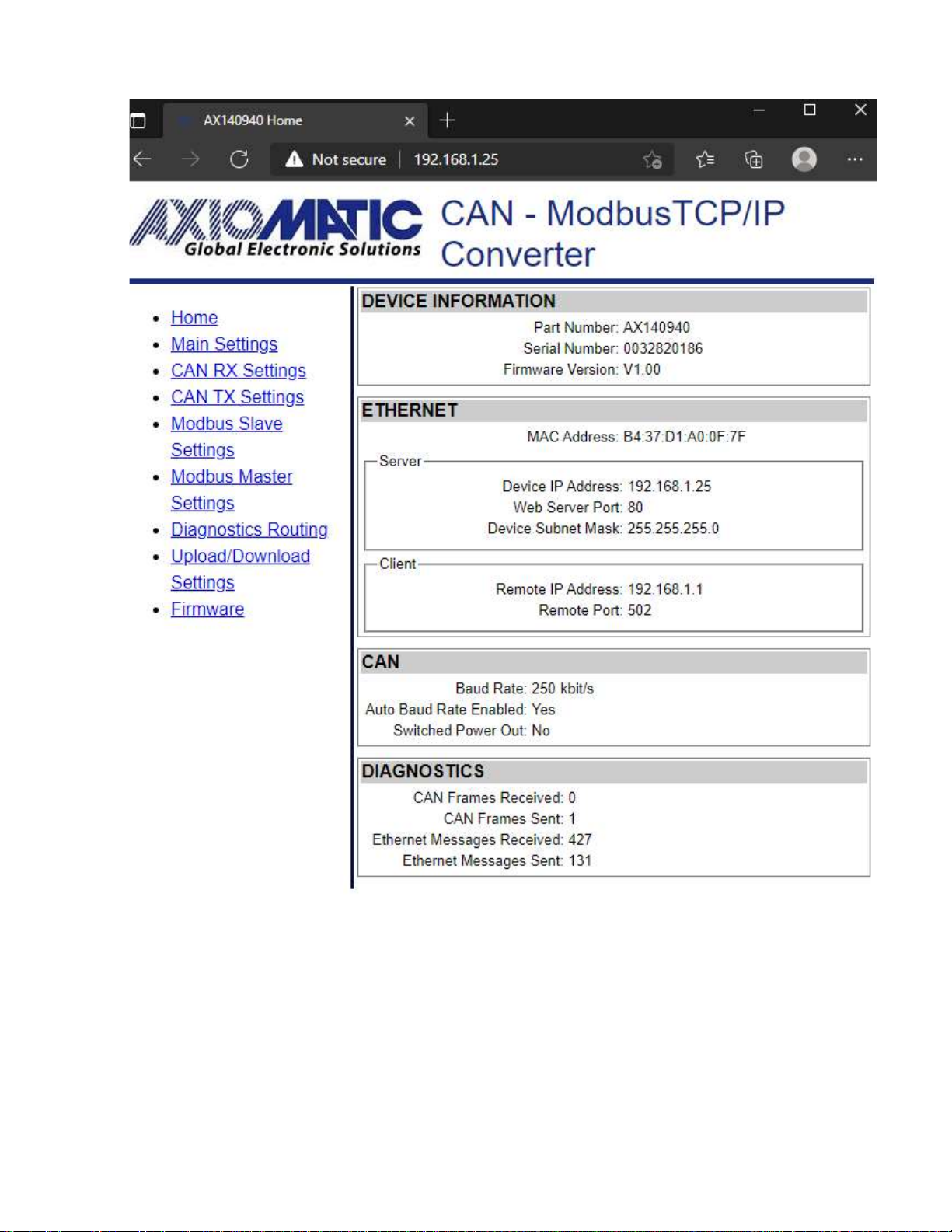
1.3.2 Web Server.................................................................................................................8
1.3.3 Firmware Updates.......................................................................................................8
2CONVERTER CONFIGURATION .......................................................................................9
2.1 Changing Configuration Parameters .............................................................................11
2.2 Ethernet Configuration...................................................................................................13
2.3 CAN Configuration.........................................................................................................14
2.3.1 CAN Rx Configuration / can_rx_settings.html...........................................................14
2.3.2 CAN Tx Configuration / can_tx_settings.html............................................................16
3Modbus TCP/IP Settings....................................................................................................18
3.1 Modbus TCP/IP Master Settings ...................................................................................19
3.2 Diagnostics Routing.......................................................................................................20
3.3 Upload/Download Settings ............................................................................................21
4FIRMWARE UPDATE........................................................................................................22
4.1 Uploading the New Firmware ........................................................................................22
4.2 Applying the New Firmware...........................................................................................23
5CONVERTER DEPLOYMENT...........................................................................................25
5.1 CAN Network Synchronization ......................................................................................25
5.1.1 Hardware Setup ........................................................................................................25
5.1.2 Converter Configuration............................................................................................26
5.1.2.1 Server Configuration .................................................................................................26
5.1.2.2 Client Configuration...................................................................................................27
6TECHNICAL SPECIFICATIONS........................................................................................30
6.1 Power Supply ................................................................................................................30
6.1.1 Input..........................................................................................................................30
6.1.2 Output .......................................................................................................................30
6.2 Ethernet.........................................................................................................................30
6.2.1 Ethernet Connector...................................................................................................31
6.3 CAN...............................................................................................................................31
6.3.1 CAN Connector.........................................................................................................31
6.4 General Specifications...................................................................................................32
6.5 Accessories...................................................................................................................32
6.6 Housing .........................................................................................................................33
7THIRD PARTY SOFTWARE LICENSE NOTICES ............................................................34

UMAX140940. CAN to Modbus TCP/IP Converter. Version 1 Page: 6-35
1. CONVERTER DESCRIPTION
The CAN to Modbus TCP/IP Converter is a simple device converting CAN frames into MODBUS
TCP/IP datagrams and sending them over the Ethernet network. The device can also convert
Modbus TCP/IP datagrams into CAN frames.
The converter has one CAN and one Ethernet port. It supports a high-speed CAN with baud rate
up to 1Mbit/s and a fast 100Mbit/s Ethernet. All standard and extended CAN frames, including
data and remote frames, are supported.
The power can be passed to the successive device through the Pout Pin. Protection is provided.
The converter contains a web server to setup configuration parameters and monitor the internal
state of the converter using a web browser. The user can also update the converter firmware
using the web browser.
To ensure low latency in processing CAN and Ethernet messages, the converter software runs
under control of a real-time operating system.
The converter is designed to work on off-road machinery or in a harsh industrial environment
with power transients, high humidity, and vibrations.
1.1 Hardware Block Diagram
The converter hardware block diagram is presented in Figure 1.
PHY MAC CAN
Microcontroller CAN
Connector
CAN
Transceiver
ETH_TX-
Ethernet
Connector
ETH_TX+
ETH_RX-
ETH_RX+
CAN_H
CAN_L
Power
Supply
BAT +
BAT -
Switch
POUT +
POUT -
CAN_SHIELD
EEPROM
BAT+
BAT -
Ethernet Link/Act
Power
FLASH
Ethernet 10/100
Figure 1. The Converter Hardware Block Diagram
The converter is powered from the Ethernet connector using dedicated power lines. The power
from the Ethernet connector can be delivered to the CAN connector through a switch controlled
by a microcontroller.
The Ethernet transformers with PHY, together with the CAN transceiver, provide Ethernet and
CAN physical interfaces.
A powerful ARM Cortex-M4 microcontroller runs IP protocol stack and all Ethernet to CAN
conversion logic.

UMAX140940. CAN to Modbus TCP/IP Converter. Version 1 Page: 7-35
1.2 LED Indicators
There are three LED indicators on the front panel of the converter. A bi-color “Power” indicator
shows whether the unit is powered. It turns red when there is an error on the CAN power output.
The two Ethernet LED indicators are hardwired to the PHY chip and show the transmission
speed “Ethernet 10/100” and the link/activity status “Ethernet Link/Act”, see Table 1:
Table 1. Converter LED Indicators
Name
Color
Description
Power
Green/Red
Off
The converter is not powered.
Green
The converter is powered. CAN Power
Output is in normal condition.
Red
CAN Power Output is in a fault condition.
Ethernet 10/100
Green
On
Ethernet speed is 100 Mbit/s
Off
Ethernet speed is 10 Mbit/s
Ethernet Link/Act
Green
On
Ethernet link is up
Off
Ethernet link is down
Blinking
Ethernet link is up and active
1.3 Firmware Organization
The Ethernet to CAN Converter firmware contains two independent parts: the Communication
Device and the Web Server, see Figure 2:
Ethernet
CAN
Communication Device Web Server
IP network
Figure 2. Converter Firmware Architecture
The Communication Device is responsible for the protocol conversion between CAN and
Ethernet networks and the Web Server provides the converter user interface.
Both the Communication Device and the Web Server use the same IP network interface. The IP
address resolution is provided by the ARP protocol.

UMAX140940. CAN to Modbus TCP/IP Converter. Version 1 Page: 8-35
1.3.1 Communication Device
The Communication Device supports a master/slave communication model to communicate
CAN messages and other auxiliary information over the Ethernet. In this model, the
Communication Device has a primary slave role, allowing external clients to establish
independent connections with the device.
In addition to the slave role, the device can also act as a master, if the Ethernet Master Enabled
configuration parameter is set to YES. In this case, the device will try to establish a connection
with a customer specified slave device.
The Communication Device uses Modbus TCP/IP protocol, The value of the Device Port for
Modbus TCP/IP will be always 502, as it is reserved for Modbus TCP/IP Communication.
1.3.1.1 TCP/IP Protocol
Modbus TCP/IP provides Master (Client) -Slave (Server) communication over Ethernet.
The server side opens a listening socket for incoming connections. Once a connection is
accepted, a new data socket is created to handle input/output communication with the remote
node. There are no restrictions on the IP address for the incoming connections.
On the client side, if “Ethernet Master Enabled”is set to YES, a data socket is created for
connection with the Slave (Server) node. The port number is assigned to the socket which is
502. If the connection drops, the device will try to automatically reconnect with the node to
maintain the client connection, if a hardware reset is provided to the device and if the device is
working as a Server (Slave), then a webserver refresh is needed to connect again.
1.3.2 Web Server
The Web Server provides a user front-end interface with the converter. It runs a dynamic website
that shows: the converter general information, configuration parameters, and the converter real-
time diagnostics.
The user can also change configuration parameters and upload the new firmware through this
website.
The web browser should support JavaScript.
1.3.3 Firmware Updates
The firmware can be remotely updated through the web server.

UMAX140940. CAN to Modbus TCP/IP Converter. Version 1 Page: 9-35
2 CONVERTER CONFIGURATION
The converter supports configuration over the internal website running on the device embedded
web server. The default “Device IP Address”is 192.168.1.25 and the default Web Server Port is
80. Please, make sure that there are no other devices on this IP address when connecting the
converter for the first time to your LAN for configuration.
To connect to the device, run any web browser and point it to the “Device IP Address”. It is not
necessary to specify the “Web Server Port”if the web server uses a standard port 80.
After a successful connection, you will see the device home page, see: Figure 3. Converter
Home Page3.

UMAX140940. CAN to Modbus TCP/IP Converter. Version 1 Page: 10-35
Figure 3. Converter Home Page
The home page shows the device information, including the converter part number, serial
number, and firmware version. It also shows Ethernet and CAN main configuration parameters
including some communication statistics (number of messages for each interface).
You will need to allow the site to run JavaScript (this setting is default in most web browsers). If
JavaScript is disabled, the website will show a message asking to activate JavaScript at the top
of the web page, see
Figure 4. Enable JavaScript Prompt
4.

UMAX140940. CAN to Modbus TCP/IP Converter. Version 1 Page: 11-35
Figure 4. Enable JavaScript Prompt
The Ethernet configuration parameters are combined into Slave (Server) and Master (Client)
groups for convenience.
The Ethernet and CAN configuration parameters have tooltips clarifying their meaning, see
Figure 55.
Figure 5. A Tooltip for the “Auto Connect to Remote” Configuration Parameter
2.1 Changing Configuration Parameters
All configuration parameters except the Modbus TCP/IP Master/Slave and CAN RX/TX settings
can be changed through the Main Settings web page. The Modbus TCP/IP Master/Slave and
CAN RX/TX configurations have their own configuration pages: For CAN RX/TX configuration,
see Figure 6.

UMAX140940. CAN to Modbus TCP/IP Converter. Version 1 Page: 12-35
The configuration pages can be reached by clicking on their links on the left side of the website.
Each configuration web page has fields to enter values of the configuration parameters and three
buttons: “Save Settings”, “Discard Settings”and “Set Defaults”.
The “Save Settings”button will save configuration parameters to non-volatile memory and apply
the new settings. The appropriate converter subsystems will be restarted without rebooting of
the whole converter except for Modbus TCP/IP Master/Slave enable/disable.
The “Discharge Settings”button will bring back the original converter settings before editing, and
the “Set Defaults”button will load the default values of the configuration parameters into the data
fields on the page.
Figure 6. Converter Main Settings Page
The configuration parameters have tooltips for the user convenience. The “Remote IP Address”
and “Remote Port”are set to 192.168.1.1 and 502 respectively. 502 is reserved for Modbus
TCP/IP Communication. When connecting to another unit that uses same IP address, or to make
a master-slave chain, do not use the same Remote IP address or same Device IP address.
Needs to change the IP Address accordingly.

UMAX140940. CAN to Modbus TCP/IP Converter. Version 1 Page: 13-35
After pressing the “Save Settings”button and saving the configuration parameters, the converter
replies with a confirmation message showing a result of the saving operation. For example, if
the user has successfully changed the CAN RX settings, the following message will appear:
Figure 7. Settings Alert. “Configuration Parameters”settings have been saved.
If no configuration is changed and the last configuration is updated again without any change,
the following message will appear:
Figure 8. Settings Alert. No changes to save!
The website messages should be enabled (not suppressed) in the browser to see this and other
feedback messages.
In case the user leaves the page without saving, all changes will be discarded. The user can
also discard changes by pressing the “Discard Changes”button.
2.2 Ethernet Configuration
All Ethernet configuration parameters can be changed through the “Main Settings”web page,
except the “MAC Address”and “Modbus TCP/IP Configuration”, which is programmed at the
factory. The user-changeable configuration parameters are presented in Table 2.
Table 2. Ethernet Configuration Parameters
Configuration
Parameter
Default Value
Range
Description
Device IP Address
192.168.0.34
Any IP address
The device IP address. The embedded
web server uses the same IP address.
Web Server Port
80
Any port value
except the
Remote Port
The communication port of the embedded
web server.
Remote IP
Address
192.168.0.35
Any IP address
The remote server IP address. Used by
the device client when the Auto Connect to
Remote is YES.
Remote Port
502
Port value –502
Modbus TCP/IP
Port
The remote server ports. Used by the
device client when the Modbus TCP/IP
Master is Enabled

UMAX140940. CAN to Modbus TCP/IP Converter. Version 1 Page: 14-35
2.3 CAN Configuration
The CAN configuration parameters can be changed through the “Main Settings”, “CAN Rx
Settings”,and “CAN Tx Settings”web pages.
The main CAN configuration parameters are available through the “Main Settings”web page,
see Table 3.
Table 3. Main CAN Configuration Parameters
Configuration
Parameter
Default Value
Range
Description
Baud Rate
250 kbit/s
{1000, 666.6(6),
500, 250, 125,
100,50, 20, 10}1
The CAN baud rate.
Auto Baud Rate
On
{Off, On}
Auto baud rate detect state.
Switched Power
Out
Off
{Off, On}
State of the switch delivering power to
the CAN connector.
1 666.6(6) kbit/s are set as 667.
The CAN filters have their own web pages for setting configuration parameters.
2.3.1 CAN Rx Configuration / can_rx_settings.html
The CAN receive message parameter settings display one message at a time. CAN Message
Select section provides ‘Next’ and ‘Previous’ buttons to go to the required message. The ‘Jump
to’ button selects the specified message directly. Settings should be saved before selecting
another CAN receive message to be configured, otherwise the modified settings will be lost.
The ‘SID: Standard ID’ checkbox allows the device to accept the CAN messages with Standard
11-bit IDs ranging from 0x0 to 0x7FF. When SID is unchecked, the device can be configured to
receive CAN messages having a specific PGN.
The ‘Discrete’ data type reads in the CAN data as a number (or bit field data), using the range
specified by the configured number of bits (Data width). With discrete data types, the resolution,
offset, minimum and maximum are not used.
The ‘Continuous’ data type uses the J1939 data formatting with resolution, offset, minimum and
maximum values. With continuous data, the data range is limited for reserving the upper range
for J1939 special and error codes.
The ‘Data destination’and ‘Data destination number’settings specify the target interface for the
received data. The received data is always stored to a local variable assigned for each CAN
receive message, but the Data destination needs to be configured for forwarding the data to the
Modbus TCP/IP slave interfaces.
The Data Destination configured as default allows us to configure the destination of CAN
messages from “CAN TX Settings”or “Modbus TCP/IP Master Settings”. CAN input data will be

UMAX140940. CAN to Modbus TCP/IP Converter. Version 1 Page: 15-35
directed accordingly. To make an internal CAN loop by configuring ‘CAN RX message’as data
destination for CAN RX.
The ‘Timeout’value specifies the amount of time for which CAN data will be stored in the input
buffer after receiving the data. Setting ‘Timeout’to 0 will allow us to use the last CAN input data
continuously until we receive a new message. Setting ‘Timeout’to any other value will expire the
current CAN input buffer after the configured timeout.
Figure 9. Converter CAN Rx Default Configuration Page
The ‘Data Maximum’specifies the maximum value received on CAN input. i.e., setting ‘Data
Maximum’to 65535, specify any value more than 0xFFFF will be filtered out.
If ‘Check Source Address’is disabled, all input CAN messages from the same PGN will be output
on the ‘Data Destination’.

UMAX140940. CAN to Modbus TCP/IP Converter. Version 1 Page: 16-35
The user can independently configure ‘CAN RX Message’Settings for each CAN Message,
through ‘CAN Receive Message Select’–‘Next’, ‘Previous’or ‘Jump to’.
“CAN RX Settings”for each message run in parallel. It is sufficient to satisfy requirements of any
active filter to pass the CAN message to the Ethernet network.
If ‘Message Enabled’is set to NO, it is considered that the CAN Rx settings for that message
are disabled, and do not participate in the message filtering process.
2.3.2 CAN Tx Configuration / can_tx_settings.html
Each of the 16 CAN transmit messages support up to 16 signals for sending out received data.
The transmit messages support the same ‘Discrete’ and ‘Continuous’ data types with same
characteristics than CAN receive messages do.
Settings should be saved before selecting a new transmit message or transmit signal. In case
the values are not saved, the modifications are lost when a new message or signal is selected.
The ‘TX interval’specifies time difference between two successive received CAN frames in milli-
seconds.
The ‘Allow TP’configured as YES, allows converter to receive more than 4 bytes continuously.
This is useful in the event when more than 2 Modbus registers need to be read at a time.
There are independent “CAN TX Settings” configuration for each CAN message.
Once the message is activated by checking the YES/NO box, the CAN messages will be
available from configured data source. Source can be Modbus TCP/IP registers, Modbus TCP/IP
master or CAN_RX, depending on TX Interval. If TX interval is set to zero, CAN port will never
receive any data from the source, as TX Interval should be more than zero except direct CAN
message is used.
Transmit Messages configured with the same PGNs will be combined as a single message if
they have a similar ‘TX Interval’. If the shared messages have overlap in Byte or bit indexing,
then the indexing configured in the higher CAN transmit message will be used. For example, if
CAN transmit messages second and third have the same PGNs and overlapping in the 5th Byte,
then the 5th Byte will contain the data of the third transmit message.
Direct CAN message from Modbus TCP/IP Master can be received as CAN frames even if TX
Interval is set to zero, as Direct CAN Message from Modbus Master will not consider “CAN TX
settings”.
All “CAN Message settings”run in parallel. It is sufficient to satisfy requirements of any active
message to send the CAN message to the Ethernet network.
If ‘Message Enabled’is set to NO, it is considered that the CAN Tx settings for that message are
disabled, and do not participate in the message filtering process.

UMAX140940. CAN to Modbus TCP/IP Converter. Version 1 Page: 17-35
Figure 10. Converter CAN ID Mask Filters Page

UMAX140940. CAN to Modbus TCP/IP Converter. Version 1 Page: 18-35
3 Modbus TCP/IP Settings
The CAN to Modbus TCP/IP Converter supports Modbus TCP/IP slaves running on Ethernet
port. The number and start address for each of the Modbus TCP/IP slave’s inputs, coils and
registers can be specified, see Figure 11.
Please note thatthe slave interface is enabled only if the Modbus TCP/IP master implementation
is not running on that interface.
The number of inputs, coils and registers have an upper limit, and the web server will not accept
values beyond the built-in maximum limit.
Figure 11. Converter Slave Settings

UMAX140940. CAN to Modbus TCP/IP Converter. Version 1 Page: 19-35
3.1 Modbus TCP/IP Master Settings
The CAN to Modbus TCP/IP Converter supports Modbus TCP/IP master running on its Ethernet
port. The ‘Ethernet Master Enable’options need to be set to YES for enabling the Modbus
TCP/IP master, see Figure 12.
Please note that enabling the Modbus TCP/IP master will disable the Modbus TCP/IP slave for
that device. As at a time one device can either work as Master or as Slave.
The Default target and Default source data routing options are the built-in variables for each
Modbus TCP/IP master message definition. The CAN receive message data target configuration
can access these variables directly if configured to do so on the CAN receive message
configuration page.
The received Modbus TCP/IP data can be also sent directly to CAN bus by selecting the ‘Direct
CAN TX’option for theForward received data to setpoint. In this case, the Received data number
specifies the J1939 PGN to use (the priority will default to 6 and the CAN to Modbus TCP/IP
Converter’s J1939 address will be used as the source address for the direct transmit messages).
Figure 12. Modbus TCP/IP Master Settings

UMAX140940. CAN to Modbus TCP/IP Converter. Version 1 Page: 20-35
3.2 Diagnostics Routing
J1939 DM1 configurable diagnostics frames can be routed to Modbus TCP/IP slave interfaces
using the Diagnostics routing configuration. There are 16 configurable diagnostics messages.
The routing options include routing all received diagnostics to Modbus TCP/IP or only routing
the specified ones. It can be configured through Diagnostics routing enabled, which has three
options in the drop list, ‘No diagnostics routing’, ‘Route specified SPN/FMI/SA’ and ‘Route all’.
In case specified diagnostics routing is configured, the SPN (Suspect Parameter Number (from
SAE J1939 standard)) is the most important parameter to configure. The diagnostics are filtered
mainly using the SPN. In case needed, the FMI and SA values can be used for more detailed
filtering of the received DM1 frames. The FMI and SA can be set to “don’t care” values (32 for
FMI and 255 for SA) for accepting a wider range of SPNs.
SPN and FMI are sent by the source on a diagnostic message. The ECU is compliant with the
standard SAE J1939. It is user’s responsibility to select SPN that will not violate J1939 standard.
For Diagnostics, DM1 –Active Diagnostic Trouble Codes supports PGN 65227 (0x00FECB).
The received DM1 data is forwarded to Modbus TCP/IP slave holding registers using the
following data layout.
Figure 13. Health Status Message on CAN Error
Table of contents
Other AXIOMATIC Media Converter manuals
Popular Media Converter manuals by other brands

TRENDnet
TRENDnet TFC-15MS100 - DATA SHEETS Specifications

Extron electronics
Extron electronics IN1608 Setup guide

Albalá Ingenieros
Albalá Ingenieros AAD2000C01 manual

Humandata
Humandata USB-304 user manual

Baumer
Baumer HOG 16 M + DSL Installation and operating instructions

Connective Peripherals
Connective Peripherals ES-U Series manual