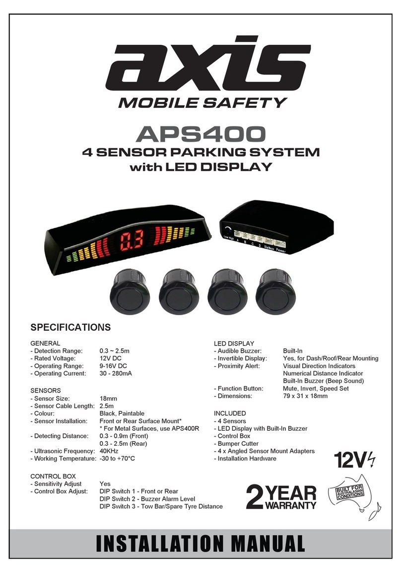
Axis APS 4R User manual

APS 4R
RUBBER PARKING SENSOR SYSTEM FOR
TRUCKS, BUSES, RV’s & CARS
USER
MANUAL
WARRANTY
Congratulations on your purchase of a quality Mobile Safety System! You’re joining
thousands of satisfied customers who enjoy & experience the benefits of the products we
distribute. In the unlikely event that some technical difficulty arises with your purchase, be
assured that we are most anxious to see that the problem is quickly rectified to your
satisfaction. Please familiarise yourself with the following simple conditions of our warranty.
This warranty covers faults through component failure or failure of the product to operate in
accordance with published specifications. Product failure as a result of unreasonable
environmental conditions, accident, misuse, improper installation, unauthorised repair, vehicle
electrical or wiring faults or neglect etc, will not be covered by this warranty. Removal and
installation costs, if any, would be paid by the owner as well as any freight or postage costs of
transporting the product to AudioXtra. AudioXtra shall not be liable or responsible for any loss
of use of this product or any form of consequential loss.
CONSUMER WARRANTY
This product is warranted by AudioXtra International Pty Ltd to be free from defects in
materials and workmanship under NORMAL USE for a period of TWENTY FOUR MONTHS
from the date of purchase.
WITHIN 30 DAYS OF PURCHASE DATE: Please return the unit for replacement to our
National Service Centre or the Retailer from where you made the purchase. All accessories
must be included. Proof of purchase date must accompany the product.
AFTER 30 DAYS OF PURCHASE DATE: Warranty repair and service is carried out by our
National Service Centre. Repair and service will be carried out at no cost to the owner if proof
of ownership and the date of purchase can be verified to the satisfaction of the authorised
centre concerned with this repair. This proof should take the form of either:
a) The warranty card accompanying this product, stamped and dated by the dealer.
b) A Tax Invoice or Receipt showing full details of original vendor, purchaser, model
number and serial number.
COMMERCIAL WARRANTY: A product used in or associated with a commercial
application will carry a limited SIX MONTH warranty. An abnormal commercial application is
one where usage, dust, vibration, heat/cold and other environmental conditions exist at an
extreme level.
Model Number: APS 4R Serial Number:
Dealer Name: Date of Purchase: / /
Dealer Address:
www.audioxtra.com.au
Purchaser’s Name:
Invoice/Sales Docket no:
Purchaser’s Address:
National Service Centre:
10 STODDART ROAD, PROSPECT, SYDNEY NSW 2148 Australia
Please complete details below in the event of warranty service being required.
General Hints:
To expedite service and prompt return of the equipment, please:
a) Clearly describe the fault in detail
b) Safety and security pack the unit for transport
c) Include your return address
d) Provide proof of purchase date as outlined above
mobile safety
PARKING SENSOR
APS 4R
APS 4T parking systems consist of ultrasonic sensors, a digital control box and a buzzer w optional LED
Display.This system detects the distance between the vehicle and rear obstructions by ultrasonic sensors
installed at the rear or front of the car or truck.
PARKING SENSOR SYSTEM
Control box
Sensors
Control box
sensitivity tuner Drill bit
Display
PARTS
GENERAL INSTALLATION DIAGRAM
Control
box
Display
Red wire — ACC +
Black wire — EARTH -
Sensor
White wire —
reversing light
Rated Voltage: 12V DC
Operating Voltage Range: 10.5-16V DC
Rated Current: 20-200mA
"BiBi" alarm sound
Hidden installation
ABCD
ABCDPower
wire
Adjust Sensitivity
Display
Display
Power
Buzzer
1
Sensitivity adjustable
SPECIFICATIONS
FEATURES
WIRING DIAGRAM
t"OUJIPPL GVODUJPO
The system will not alarm if there is a tow bar or spare tyre on the back of the vehicle.
NEW FEATURES
Detection Range: 0.2-1.5m
Ultrasonic Frequency: 40KHz
o
Control Working Temperature: -30-+70 C
ON OFF
Control box
20 cm on/off function
tDN GVODUJPO
There is a “on/off” switch on the back of the control unit. If you choose “on”, the alarming distance will
be 20cm shorter than the real distance. forThis is used vehicles with a spare tyre or other accessory
on the back. The sensors then detect distances between obstacles and the spare tyre, instead of obstacles
and the bumper.
Buzzer Size:
2-4 surface mount sensors
42 x 16
ALARM MODE
1
2
3
4
5
Stages Distance Awar enes s Alarm sound
Saf ety Ar ea Silen ce
Dang er Area
0.7-0.9m
0.4-0.6m
<0.3m
Alar m Ar ea
Saf ety Ar ea
Alar m Ar ea
>1.5m
1.0-1.5m Bi.........Bi.........
Bi......Bi......
Bi...Bi...
Bi...
Digital control box is installed
inside the boot.
Keep away from heat, moisture
and vibration
Rubber Sensors (Avoid false alarms in thick
metal bumpers)

1. Adjust the direction and orientation of the sensors. Neaten the cables after sensor installation.
2. Connect wires to control box: red — “ACC”, black — “ground”, white — “reversing signal”
Connect the wire between control box and display (keep the sensors disconnected).
3. Start the vehicle.
4. With ignition on, select reverse gear. The reversing light should turn on. Insert a sensor to the control box.
Obstacles should be detected if standing within 1m. Remove the sensor and continue to test other sensors.
5. Start the vehicle in reverse gear. Place an obstacle to make the system alarm.
Pay special attention to the following during the installation and adjustment of sensors:
a. If the system beeps as “Bi...” after one sensor is connected, please check whether there is any
obstacle, or the sensor is fitted too tightly or close to a major interference source (such as exhaust or
power cables);
b. If the system beeps as “Bi... Bi...” and there are no obstacles, the sensor may be detecting the
ground or some accessories (such as number plates, etc.). Please check the direction and axis
of the sensors.
c. If the sensor still fails to work properly after the above testing, the sensor may be defective or
incompatible with the control box. The system should be replaced.
d. Please pay attention to the markings of sensors like A.B.C.D when connecting to control box. The
mark on the sensor should correspond to the mark on the control box.
e. If the distance from the obstacle to the vehicle is <0.3m, it will show “0.0” in the display
(but not 0.2/0.1m) to warn the driver to stop the vehicle..
INSTALLATION ANDSENSOR TEST
NOTE
1. The vehicle must be switched offf during installation of the system.
2. Immediate performance may be affected in the following situations: heavy rain, gravel roads, bumpy
and sloping roads, extreme cold, hot or moist weather, or if the sensor is covered by mud, snow,
ice, etc.
3. Switchmode devices & power inverters may also affect performance.
4. The sensors should be installed securely, but not over-tight.
5. Performance may be affected if the sensors are installed on a heavy metal bumper..
6. Avoid installing the digital control box in areas of interference or moisture.
7. Test the system to make sure it works normally before use.
8. This system is a reversing aid and the manufacturer will take no responsibility for any
accidents caused after the kit is installed.
After testing, connect all 4 sensors to the corresponding ports of the control box.
Other Axis Automobile Electronic manuals
Popular Automobile Electronic manuals by other brands

Streamax
Streamax A5-E0804 MDVR user manual

SecurView
SecurView SV-6826.II installation instructions

VDO
VDO VIEWLINE 85 MM - MOUNTING 11-09 installation instructions

Adaptiv
Adaptiv Adaptiv Mini FITTING & USER GUIDE

KAP
KAP MB 2010 PAS DC3 instruction manual

Continental Refrigerator
Continental Refrigerator KIBES brochure