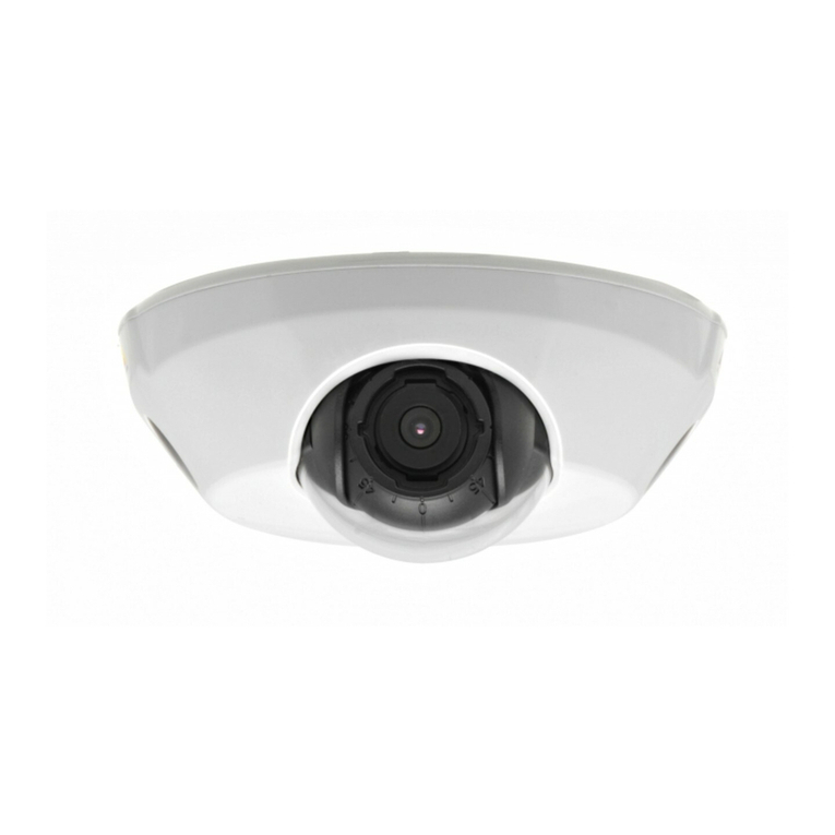
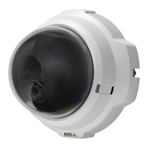
Axis P3343 User manual

ENGLISH
INSTALLATION GUIDE
Drop Ceiling Mount
for
AXIS P3343 Network Camera
AXIS P3344 Network Camera

About this Document
This document includes instructions for installing the
AXIS P3343/AXIS P3344 Drop Ceiling Mount.
Equipment Modifications
This equipment must be installed and used in strict
accordance with the instructions given in the user
documentation.
Liability
Every care has been taken in the preparation of this
document. Please inform your local Axis office of any
inaccuracies or omissions. Axis Communications AB
cannot be held responsible for any technical or
typographical errors and reserves the right to make
changes to the product and documentation without
prior notice. Axis Communications AB makes no
warranty of any kind with regard to the material
contained within this document, including, but not
limited to, the implied warranties of merchantability
and fitness for a particular purpose. Axis
Communications AB shall not be liable nor responsible
for incidental or consequential damages in connection
with the furnishing, performance or use of this material.
Support
Should you require any technical assistance, please
contact your Axis reseller. If your questions cannot be
answered immediately, your reseller will forward your
queries through the appropriate channels to ensure a
rapid response. If you are connected to the Internet, you
can:
• find answers to resolved problems in the FAQ database.
Search by product, category, or phrases
• report problems to Axis support by logging in to your
private support area.
Drop Ceiling Mount Installation Guide Page 3
ENGLISH
Drop Ceiling Mount Installation Guide
This installation guide provides instructions for installing the drop ceiling mount for the AXIS P3343
and AXIS P3344 Network Cameras. Please read through the entire guide before proceeding with the
installation.
For all other aspects of using the Axis network camera, please see the Installation Guide and User’s
Manual, available from www.axis.com/techsup
Installation steps
• Check the package contents against
the list on page 4.
• Installation instructions. See page 6.
Important!
This product must be used in
compliance with local laws and
regulations.

Page 4 Drop Ceiling Mount Installation Guide
Package contents
• 1 Plastic dome cover
• 1 Ceiling bracket
• 1 Drop Ceiling Mount Installation Guide (this document)
• 1 Hole template
• 1 Safety wire & M4x6 screw
Ceiling bracket
(bottom)
Logotype arrow points to where the
logo will appear when the installation
is complete
Plastic dome cover
Captive
screws
Logotype
Safety wire
Ceiling bracket
(top)
Support arms
Support arm
screws
Alternate
screw
holes (4x)

Drop Ceiling Mount Installation Guide Page 5
ENGLISH
Specifications
• Total weight (camera plus ceiling mount): 0.9kg (2.0lb)
• Plastic dome cover diameter: 191mm (7.5”)
• Ceiling hole (ceiling bracket top) diameter: 162mm (6.4”)
• Cable hole for gasket (2 holes) diameter: 21mm (0.8“)
• Ceiling thickness: 10-60mm (0.4” - 2.4”), if you are using the support arms to secure the
drop ceiling mount into place.
Ceiling bracket
(top)
Plastic dome cover
Cable holes for gaskets
Ceiling bracket
(side view)
Ø21mm/0.8”
Ø191mm/7.5”
162mm/6.4”
82mm/3.2”
63mm/2.5”
10-60mm/
0.4-2.4”
48mm/1.9”

Page 6 Drop Ceiling Mount Installation Guide
Install the Drop Ceiling Mount
1. If possible, remove the ceiling tile in which the drop ceiling mount is to be fitted.
2. Use the supplied template to mark the position for the 162mm (6.4”) hole in the ceiling tile.
Remove the protective paper, fix to ceiling tile and cut around the template.
Notes:
• The combined weight of the camera and ceiling mount is 0.9kg (2.0lb). Check that the ceiling
material is strong enough to support this weight.
• The thickness of the ceiling tile should be 10-60mm (0.4” - 2.4”).
3. For greater security, the camera can be secured using the supplied safety wire. Replace the
ceiling tile, and attach the end of the safety wire with the lock to a suitable point in the ceiling
above the drop ceiling.
Ceiling tile
Hole diameter 162mm/6.4”
Attach to ceiling

Drop Ceiling Mount Installation Guide Page 7
ENGLISH
4. Remove the black foam gasket from the cable hole, fit it around the network cable, and replace
the foam gasket and network cable back into the cable hole.
5. Put the ceiling bracket up into the ceiling, and position the logotype labels where you want the
logotypes on the plastic cover.
Cable hole
Foam gasket
Network cable

Page 8 Drop Ceiling Mount Installation Guide
6. Tighten the support arm screws using a torx 20 screwdriver head.
Notes:
• If your ceiling is not between 10-60mm (0.4” - 2.4”), or if you are not using the support arms, you
can also secure the ceiling bracket into place using the four alternate screw holes.
• If you do secure the drop ceiling mount using the alternate screw holes, use flat head screws to
secure the ceiling bracket, which will not interfer with attachment of the plastic dome cover.
When the support arm screws are tightened, the support arms fold out over the ceiling and lock
into place against the sides of the ceiling bracket to support and keep the drop ceiling mount in
place.
Supportarm
screws
Alternate screw
holes (4x)
Support arms

Drop Ceiling Mount Installation Guide Page 9
ENGLISH
7. Connect the network cable to the camera, and then snap the camera into place in the ceiling
bracket.
8. Using the camera’s installation guide, adjust the camera’s lens before you attach the plastic
dome cover.
9. Rotate the black protective shield inside the plastic dome cover so it is aligned with the
camera’s position.
Network cable
Black protective
cover
Camera holder

Page 10 Drop Ceiling Mount Installation Guide
10. Place the plastic dome cover over the ceiling bracket and tighten it into place using a resitorx
20 (i.e., tamper proof) screwdriver to tighten the captive screws into place.
Captive screws

Guide d’installation du kit de montage pour faux-plafond Page 11
FRANÇAIS
Guide d’installation du kit de montage pour faux-
plafond
Le présent guide fournit des instructions d’installation pour le kit de montage pour faux-plafond
pour les caméras réseau AXIS P3343 et AXIS P3344. Veuillez lire l’intégralité du guide avant de
procéder à l’installation.
Pour toute autre instruction d’utilisation de la caméra réseau Axis, veuillez consulter le guide
d’installation et le manuel de l’utilisateur, disponibles sur le site www.axis.com/techsup
Procédure d’installation
• Vérifiez le contenu de l’emballage par rapport
à la liste à la page 12.
• Instructions d’installation. Reportez-vous à la
page 14.
Important !
Ce produit doit être utilisé
conformément aux lois et
dispositions locales en vigueur.

Page 12 Guide d’installation du kit de montage pour faux-plafond
Contenu de l’emballage
• 1 Couvercle de dôme en plastique
• 1 Support pour installation au plafond
• 1 Guide d’installation du kit de montage pour faux-plafond (le présent document)
• 1 Modèle de trou
• 1 Fil de sécurité + vis M4x6
Support pour installation au plafond
(vue de dessous)
La flèche du logo pointe vers l’endroit où le
logo apparaîtra une fois l’installation
terminée
Couvercle de dôme en plastique
Vis imperdables
Logo
Fil de sécurité
Support pour installation au plafond
(vue de dessus)
Bras de
support
Vis du bras
de support
Autres
trous de
vis (x4)

Guide d’installation du kit de montage pour faux-plafond Page 13
FRANÇAIS
Caractéristiques techniques
• Poids total (caméra + kit de montage) : 0,9 kg
• Diamètre du couvercle de dôme en plastique : 191 mm
• Diamètre du trou au plafond (partie supérieure du support) : 162 mm
• Diamètre des trous de câble pour les joints (2 trous) : 21 mm
• Épaisseur du plafond : de 10 à 60 mm, si vous utilisez les bras de support pour fixer le kit de
montage.
Support pour installation au plafond
(vue de dessus)
Couvercle de dôme en plastique
Trous de câble pour les joints
Support pour installation au plafond
(vue latérale)
Ø21mm/0.8”
Ø191mm/7.5”
162mm/6.4”
82mm/3.2”
63mm/2.5”
10-60mm/
0.4-2.4”
48mm/1.9”

Page 14 Guide d’installation du kit de montage pour faux-plafond
Installation du kit de montage pour faux-plafond
1. Retirez, si possible, la plaque de plafond sur laquelle le kit de montage doit être fixé.
2. Utilisez le modèle fourni pour marquer l’emplacement du trou de 162 mm dans la plaque de
plafond. Retirez le film protecteur, fixez le support sur la plaque et coupez en suivant le modèle.
Remarques :
• Le poids total de la caméra et du kit de montage est de 0,9 kg. Assurez-vous que le matériau du
plafond est suffisamment solide pour supporter ce poids.
• L’épaisseur de la plaque de plafond doit être de 10 à 60 mm.
3. Pour plus de sécurité, la caméra peut être fixée à l’aide du fil de sécurité fourni. Replacez la
plaque de plafond et attachez l’extrémité du fil de sécurité, avec le dispositif de verrouillage, à
un endroit adéquat sur le plafond, au-dessus du faux-plafond.
Plaque de plafond
Diamètre du trou 162mm/6.4”
À attacher au plafond

Guide d’installation du kit de montage pour faux-plafond Page 15
FRANÇAIS
4. Retirez le joint en mousse noir du trou de câble, disposez-le autour du câble réseau puis
replacez le joint en mousse et le câble réseau dans le trou de câble.
5. Placez le support au plafond et positionnez les étiquettes du logo à l’endroit où vous souhaitez
que le logo apparaisse sur le couvercle en plastique.
Trou de câble
Joint en mousse
Câble réseau

Page 16 Guide d’installation du kit de montage pour faux-plafond
6. Serrez les vis du bras de support à l’aide d’un tournevis torx 20.
Remarques :
• Si l’épaisseur de votre plafond n’est pas comprise entre 10 et 60 mm ou si vous n’utilisez pas les bras
de support, vous pouvez également fixer le support pour plafond à l’aide des quatre autres trous de
vis.
• Le cas échéant, utilisez des vis à tête plate qui ne gêneront pas l’attache du couvercle de dôme en
plastique.
Une fois les vis des bras de support serrées, les bras de support se déplient et se bloquent contre les
côtés du support afin de maintenir le kit de montage pour faux-plafond en place.
Vis du bras
de support
Autres trous de
vis (x4)
Bras de support

Guide d’installation du kit de montage pour faux-plafond Page 17
FRANÇAIS
7. Connectez le câble réseau à la caméra, puis insérez la caméra dans le support.
8. Réglez l’objectif de la caméra en suivant les instructions de son guide d’installation, avant de
fixer le couvercle du dôme en plastique.
9. Tournez l’écran protecteur noir à l’intérieur du couvercle du dôme afin d’aligner ce dernier sur la
position de la caméra.
Câble réseau
Couvercle
protecteur noir
Support de caméra

Page 18 Guide d’installation du kit de montage pour faux-plafond
10. Placez le couvercle du dôme en plastique sur le support de montage et serrez-le à l’aide d’un
tournevis resitorx 20 (pour vis inviolables) et de vis imperdables.
Vis
imperdables

Installationsanleitung für die Halterung für Hängedecken Seite 19
DEUTSCH
Installationsanleitung für die Halterung für
Hängedecken
Dieses Handbuch enthält Anweisungen zur Anbringung der Halterung für Hängedecken für die
Netzwerk-Kameramodelle AXIS P3343 und AXIS P3344. Bitte lesen Sie zunächst das Handbuch
vollständig durch, bevor Sie mit der Installation beginnen.
Alle weiteren Hinweise zur Verwendung der Axis Netzwerk-Kamera finden Sie im
Installationshandbuch und im Benutzerhandbuch, die auf unserer Website unter www.axis.com/
techsup zur Verfügung stehen.
Installationsschritte
• Überprüfen Sie den Paketinhalt mit der
Liste auf Seite 20.
• Installationsanweisungen. Siehe Seite 22.
Wichtig!
Verwenden Sie dieses Produkt
unter Beachtung der geltenden
rechtlichen Bestimmungen.

Seite 20 Installationsanleitung für die Halterung für Hängedecken
Paketinhalt
• 1 Kunststoff-Kuppelabdeckung
• 1 Deckenhalterung
• 1 Installationsanleitung für die Halterung für Hängedecken (dieses Dokument)
•1Kreisschablone
• 1 Sicherheitsdraht und M4x6-Schraube
Deckenhalterung
(unten)
LOGOTYPE-Pfeil
zeigt auf die Stelle, an der
das Logo nach der Installation
erscheint
Kunststoff-Kuppelabdeckung
unverlierbare
Schrauben
LOGOTYPE-Pfeil
Sicherheitsdraht
Deckenhalterung
(oben)
Haltevorrichtungen
Schrauben für
Haltevorrichtung
4 alternative
Schraublöcher
Other manuals for P3343
4
This manual suits for next models
1
Table of contents
Languages:
Other Axis Security Camera manuals

Axis
Axis P5415-E PTZ User manual

Axis
Axis P14 Series User manual

Axis
Axis XF40-Q1765 User manual

Axis
Axis M5013 User manual

Axis
Axis Q6100-E User manual

Axis
Axis T91A51 User manual

Axis
Axis Q6032-E PTZ User manual

Axis
Axis P3224-LV Mk II User manual

Axis
Axis M30 Series User manual

Axis
Axis M42 Series User manual