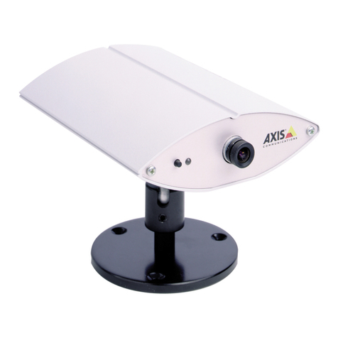
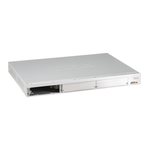
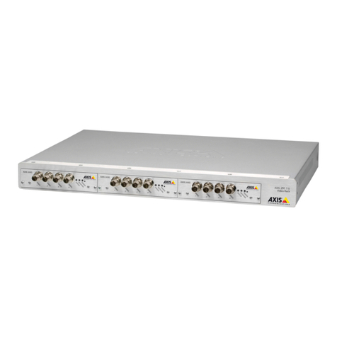
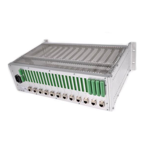
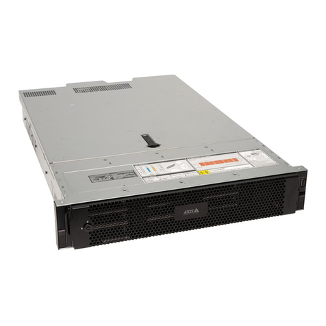
Axis 241Q Blade User manual

AXIS 241Q and AXIS 241S
Video Servers
User’s Manual
Installation instructions are also available in German, French, Italian and Spanish in this manual

AXIS COMMUNICATIONS
<Product Name> Quick User’s Guide
2 About This Document
This manual is intended for administrators and users of the
AXIS 241Q/241S Video Server, and is applicable for
software release 4.00. It includes instructions for installing,
using and managing the AXIS 241Q/241S on your network.
Previous experience of networking will be of use when
installing and using this product. Some knowledge of UNIX
or Linux-based systems would also be beneficial, for
developing shell scripts and applications. Later versions of
this document will be posted to the Axis Website, as
required. See also the product’s online help, available via
the Web-based interface.
Safety Notices Used In This Manual
Caution! - Indicates a potential hazard that can damage the
product.
Important! - Indicates a hazard that can seriously impair
operation.
Do not proceed beyond any of the above notices until you
have fully understood the implications.
Intellectual Property Rights
Axis AB has intellectual property rights relating to
technology embodied in the product described in this
document. In particular, and without limitation, these
intellectual property rights may include one or more of the
patents listed at http://www.axis.com/patent.htm and one
or more additional patents or pending patent applications
in the US and other countries.
Legal Considerations
Camera surveillance can be prohibited by laws that vary
from country to country. Check the laws in your local
region before using this product for surveillance purposes.
Electromagnetic Compatibility (EMC)
This equipment generates, uses and can radiate radio
frequency energy and, if not installed and used in
accordance with the instructions, may cause harmful
interference to radio communications. However, there is no
guarantee that interference will not occur in a particular
installation.
If this equipment does cause harmful interference to radio
or television reception, which can be determined by turning
the equipment off and on, the user is encouraged to try to
correct the interference by one or more of the following
measures: Re-orient or relocate the receiving antenna.
Increase the separation between the equipment and
receiver. Connect the equipment to an outlet on a different
circuit to the receiver. Consult your dealer or an
experienced radio/TV technician for help. Shielded (STP)
network cables must be used with this unit to ensure
compliance with EMC standards.
USA - This equipment has been tested and found to
comply with the limits for a Class B computing device
pursuant to Subpart B of Part 15 of FCC rules, which are
designed to provide reasonable protection against such
interference when operated in a commercial environment.
Operation of this equipment in a residential area is likely to
cause interference, in which case the user at his/her own
expense will be required to take whatever measures may be
required to correct the interference.
Europe - This digital equipment fulfills the
requirements for radiated emission according to limit B of
EN55022/1998, and the requirements for immunity
according to EN55024/1998 residential, commercial, and
light industry.
Liability
Every care has been taken in the preparation of this manual;
Please inform your local Axis office of any inaccuracies or
omissions. Axis Communications AB cannot be held responsible
for any technical or typographical errors and reserves the right
to make changes to the product and manuals without prior
notice. Axis Communications AB makes no warranty of any
kind with regard to the material contained within this
document, including, but not limited to, the implied warranties
of merchantability and fitness for a particular purpose. Axis
Communications AB shall not be liable nor responsible for
incidental or consequential damages in connection with the
furnishing, performance or use of this material.
Trademark Acknowledgments
Acrobat, Adobe, Boa, Ethernet, IBM, Internet Explorer, LAN
Manager, Linux, Macintosh, Microsoft, Mozilla, Netscape
Navigator, OS/2, UNIX, Windows, WWW are registered
trademarks of the respective holders. Java and all Java-based
trademarks and logos are trademarks or registered trademarks
of Sun Microsystems, Inc. in the United States and other
countries. UPnP is a certification mark of the UPnPTM
Implementers Corporation. Axis Communications AB is
independent of Sun Microsystems Inc.
Support Services
Should you require any technical assistance, please contact
your Axis reseller. If your questions cannot be answered
immediately, your reseller will forward your queries through
the appropriate channels to ensure a rapid response. If you are
connected to the Internet, you can:
• download user documentation and firmware updates
• find answers to resolved problems in the FAQ database.
Search by product, category, or phrases
• report problems to Axis support staff by logging in to your
private support area
• visit the Axis Support Web at www.axis.com/techsup/
Safety Notice - Battery Replacement
The AXIS 241Q/241S uses a 3.0V CR2032 Lithium battery as
the power supply for its internal real-time clock (RTC). This
battery will, under normal conditions, last for a minimum of 5
years. Low battery power affects the operation of the RTC,
causing it to reset at every power-up. A log message will appear
when battery replacement is required.
The battery should not be replaced unless required!
If the battery does need replacing, please observe the following
points:
Caution!
• Danger of Explosion if battery is incorrectly replaced
• Replace only with the same or equivalent battery, as
recommended by the manufacturer.
• Dispose of used batteries according to the manufacturer's
instructions.
AXIS 241Q/241S User’s Manual Revision 1.00
Dated: January 2004 Part No: 20995
Copyright © Axis Communications AB, 2004

3
AXIS 241Q/241S
Table of contents
Product Description . . . . . . . . . . . . . . . . . . . . . . . . . . . . . . . . . . . . . . . . . . . . . . . . . . . . . . . . . . . . . . 5
Hardware Inventory . . . . . . . . . . . . . . . . . . . . . . . . . . . . . . . . . . . . . . . . . . . . . . . . . . . 5
AXIS 241Q Front Panel. . . . . . . . . . . . . . . . . . . . . . . . . . . . . . . . . . . . . . . . . . . . . . . . . 6
AXIS 241S Front Panel . . . . . . . . . . . . . . . . . . . . . . . . . . . . . . . . . . . . . . . . . . . . . . . . 7
AXIS 241Q/241S Rear Panel . . . . . . . . . . . . . . . . . . . . . . . . . . . . . . . . . . . . . . . . . . . . 8
Installing the AXIS 241Q/241S . . . . . . . . . . . . . . . . . . . . . . . . . . . . . . . . . . . . . . . . . . . . . . . . . . . . . 9
Mounting the AXIS 241Q/241S. . . . . . . . . . . . . . . . . . . . . . . . . . . . . . . . . . . . . . . . . . 9
Connecting video cameras to the AXIS 241Q/241S . . . . . . . . . . . . . . . . . . . . . . . . . 9
Installing on a network . . . . . . . . . . . . . . . . . . . . . . . . . . . . . . . . . . . . . . . . . . . . . . . . 9
Manual Installation using AXIS IP Utility . . . . . . . . . . . . . . . . . . . . . . . . . . . . . . . . 10
Manual Installation using ARP and Ping in Windows . . . . . . . . . . . . . . . . . . . . . . 11
Manual Installation using ARP and Ping in UNIX/Linux . . . . . . . . . . . . . . . . . . . . . 12
Using the video server . . . . . . . . . . . . . . . . . . . . . . . . . . . . . . . . . . . . . . . . . . . . . . . . . . . . . . . . . . . 14
Accessing the video server. . . . . . . . . . . . . . . . . . . . . . . . . . . . . . . . . . . . . . . . . . . . . 14
Configuring the video server . . . . . . . . . . . . . . . . . . . . . . . . . . . . . . . . . . . . . . . . . . . . . . . . . . . . . . 17
Accessing the Setup tools . . . . . . . . . . . . . . . . . . . . . . . . . . . . . . . . . . . . . . . . . . . . . 17
Overview of the Setup tools . . . . . . . . . . . . . . . . . . . . . . . . . . . . . . . . . . . . . . . . . . . 17
Using the Setup Tools . . . . . . . . . . . . . . . . . . . . . . . . . . . . . . . . . . . . . . . . . . . . . . . . 20
Event Configuration . . . . . . . . . . . . . . . . . . . . . . . . . . . . . . . . . . . . . . . . . . . . . . . . . . . . . . . . . . . . . 27
Event Servers. . . . . . . . . . . . . . . . . . . . . . . . . . . . . . . . . . . . . . . . . . . . . . . . . . . . . . . . 27
Event Types . . . . . . . . . . . . . . . . . . . . . . . . . . . . . . . . . . . . . . . . . . . . . . . . . . . . . . . . 28
Motion Detection. . . . . . . . . . . . . . . . . . . . . . . . . . . . . . . . . . . . . . . . . . . . . . . . . . . . 30
Port Status . . . . . . . . . . . . . . . . . . . . . . . . . . . . . . . . . . . . . . . . . . . . . . . . . . . . . . . . . 31
System Options. . . . . . . . . . . . . . . . . . . . . . . . . . . . . . . . . . . . . . . . . . . . . . . . . . . . . . . . . . . . . . . . . 32
Security. . . . . . . . . . . . . . . . . . . . . . . . . . . . . . . . . . . . . . . . . . . . . . . . . . . . . . . . . . . . 32
Date & Time . . . . . . . . . . . . . . . . . . . . . . . . . . . . . . . . . . . . . . . . . . . . . . . . . . . . . . . . 33
Network - TCP/IP Settings. . . . . . . . . . . . . . . . . . . . . . . . . . . . . . . . . . . . . . . . . . . . . 34
SOCKS . . . . . . . . . . . . . . . . . . . . . . . . . . . . . . . . . . . . . . . . . . . . . . . . . . . . . . . . . . . . . 35
SMTP (email). . . . . . . . . . . . . . . . . . . . . . . . . . . . . . . . . . . . . . . . . . . . . . . . . . . . . . . . 36
UPnP . . . . . . . . . . . . . . . . . . . . . . . . . . . . . . . . . . . . . . . . . . . . . . . . . . . . . . . . . . . . . .36
Ports & Devices. . . . . . . . . . . . . . . . . . . . . . . . . . . . . . . . . . . . . . . . . . . . . . . . . . . . . . 36
Maintenance. . . . . . . . . . . . . . . . . . . . . . . . . . . . . . . . . . . . . . . . . . . . . . . . . . . . . . . . 36
Support . . . . . . . . . . . . . . . . . . . . . . . . . . . . . . . . . . . . . . . . . . . . . . . . . . . . . . . . . . . . 37
Advanced. . . . . . . . . . . . . . . . . . . . . . . . . . . . . . . . . . . . . . . . . . . . . . . . . . . . . . . . . . . 37
Resetting to Factory Default Settings . . . . . . . . . . . . . . . . . . . . . . . . . . . . . . . . . . . 38

4 AXIS 241Q/241S
Unit Connections . . . . . . . . . . . . . . . . . . . . . . . . . . . . . . . . . . . . . . . . . . . . . . . . . . . . . . . . . . . . . . . 39
The D-Sub Connector. . . . . . . . . . . . . . . . . . . . . . . . . . . . . . . . . . . . . . . . . . . . . . . . .39
The I/O Terminal Block . . . . . . . . . . . . . . . . . . . . . . . . . . . . . . . . . . . . . . . . . . . . . . .40
COM Port RS232/PTZ and COM Port RS485. . . . . . . . . . . . . . . . . . . . . . . . . . . . . . .41
Connecting Pan/Tilt Devices . . . . . . . . . . . . . . . . . . . . . . . . . . . . . . . . . . . . . . . . . . .41
Y/C TO BNC CABLE (AXIS 241S only) . . . . . . . . . . . . . . . . . . . . . . . . . . . . . . . . . . . .43
Troubleshooting . . . . . . . . . . . . . . . . . . . . . . . . . . . . . . . . . . . . . . . . . . . . . . . . . . . . . . . . . . . . . . . . 44
Checking the Firmware . . . . . . . . . . . . . . . . . . . . . . . . . . . . . . . . . . . . . . . . . . . . . . .44
Updating the Firmware . . . . . . . . . . . . . . . . . . . . . . . . . . . . . . . . . . . . . . . . . . . . . . .44
Support . . . . . . . . . . . . . . . . . . . . . . . . . . . . . . . . . . . . . . . . . . . . . . . . . . . . . . . . . . . .45
Technical Specifications. . . . . . . . . . . . . . . . . . . . . . . . . . . . . . . . . . . . . . . . . . . . . . . . . . . . . . . . . . 47
Performance . . . . . . . . . . . . . . . . . . . . . . . . . . . . . . . . . . . . . . . . . . . . . . . . . . . . . . . .48
Installieren des AXIS 241Q/241S. . . . . . . . . . . . . . . . . . . . . . . . . . . . . . . . . . . . . . . . . . . . . . . . . . .49
Montage des AXIS 241Q/241S . . . . . . . . . . . . . . . . . . . . . . . . . . . . . . . . . . . . . . . . .49
Anschluss der Videokameras an den AXIS 241Q/241S . . . . . . . . . . . . . . . . . . . . . . 49
Installieren in einem Netzwerk . . . . . . . . . . . . . . . . . . . . . . . . . . . . . . . . . . . . . . . . .49
Installation du serveur AXIS 241Q/241S. . . . . . . . . . . . . . . . . . . . . . . . . . . . . . . . . . . . . . . . . . . . .54
Montage du serveur AXIS 241Q/241S . . . . . . . . . . . . . . . . . . . . . . . . . . . . . . . . . . .54
Connexion des caméras vidéos à AXIS 241Q/241S . . . . . . . . . . . . . . . . . . . . . . . . .54
Installation sur un réseau . . . . . . . . . . . . . . . . . . . . . . . . . . . . . . . . . . . . . . . . . . . . .54
Installazione di AXIS 241Q/241S. . . . . . . . . . . . . . . . . . . . . . . . . . . . . . . . . . . . . . . . . . . . . . . . . . .59
Montaggio di AXIS 241Q/241S . . . . . . . . . . . . . . . . . . . . . . . . . . . . . . . . . . . . . . . . .59
Connessione delle videocamere ad AXIS 241Q/241S . . . . . . . . . . . . . . . . . . . . . . .59
Installazione su una rete . . . . . . . . . . . . . . . . . . . . . . . . . . . . . . . . . . . . . . . . . . . . . .59
Instalación del AXIS 241Q/241S . . . . . . . . . . . . . . . . . . . . . . . . . . . . . . . . . . . . . . . . . . . . . . . . . . .64
Montaje del AXIS 241Q/241S . . . . . . . . . . . . . . . . . . . . . . . . . . . . . . . . . . . . . . . . . .64
Conexión de cámaras de vídeo al AXIS 241Q/241S. . . . . . . . . . . . . . . . . . . . . . . . .64
Instalación en una red . . . . . . . . . . . . . . . . . . . . . . . . . . . . . . . . . . . . . . . . . . . . . . . .64
Index . . . . . . . . . . . . . . . . . . . . . . . . . . . . . . . . . . . . . . . . . . . . . . . . . . . . . . . . . . . . . . . . . . . . . . . . .69

5
AXIS 241Q/241S - Product Description
Product Description
The AXIS 241Q/S is a new generation, full-featured video server for security surveillance
and remote monitoring needs, based around the new AXIS ARTPEC-2 compression chip. It
has the ability to digitize up to 4 analog video sources and make these available on the
network as streams of real time full frame rate Motion JPEG video.
The AXIS 241Q is equipped with 4 BNC inputs for analog video devices and the AXIS 241S
is equipped with 1 BNC input and a matching loop-through output. The AXIS 241S can
also accommodate Y/C video using an Y/C to BNC cable (not included). The AXIS
241Q/241S is equipped with RS232 and 485 ports for connection of third party PTZ
systems and 4 alarm inputs and 4 alarm outputs, which can be connected to various third
party devices, e.g. door sensors and alarm bells. Up to 20 viewers can access the unit
simultaneously.
Video can be viewed in 10 resolutions (up to 768x576), each with 5 quality levels. The
video server contains Video Motion Detection, which allows the unit to trigger on activity
in the video image, and advanced scheduling tools which can also be used to trigger an
event. As the AXIS 241Q/241S is designed for use in security systems, it is equipped with
several security features, such as IP address filtering, multilevel password and HTTPS.
The AXIS 241Q/241S has a built-in Web server, providing full access to all features
through the use of a standard Web browser. The built-in script tool allows basic
applications to be created, providing basic surveillance solutions. For advanced
functionality, the video server is easy to integrate through the use of AXIS HTTP API (more
info on www.axis.com/developer)
Hardware Inventory
Check the items supplied with your AXIS 241Q/241S against the following list:
Item Title/Variants
Video Server AXIS 241Q
AXIS 241S
This document AXIS 241Q/241S User’s Manual
Warranty Document
Power Supply
PS-K
Europe
UK
Australia
USA/Japan
Korea
Terminal Connector 12 PIN
Mounting Kit
Optional Accessories ACC Y/C TO BNC CABLE (AXIS 241S only)
Part No. 21339
The power supply is country
specific, please check that the
type of power supply you are
using is correct.

6 AXIS 241Q/241S - Product Description
AXIS 241Q Front Panel
Indicators - After completion of the startup and self test routines, the multi-colored
Network, Status, Power Indicators flash as follows:
DIP Switches - A corresponding line termination switch for each of the supported video
inputs. All units are shipped with the line termination enabled for each supported video
input; that is, with the DIP switches set in the down-position.
Note: If the AXIS 241Q is to be connected in parallel with other equipment, disable the input termination by
turning the corresponding DIP switch to the up-position (OFF). Failure to do this may cause reduced image
quality.
Control Button - Press this button to restore the factory default settings, as described in
Resetting to Factory Default Settings, on page 38 or to install using AXIS Internet Dynamic
DNS Service (page 13).
Video Inputs - Accommodates up to 4 separate video sources (VIDEO 1- VIDEO 4)
simultaneously. Each supported video input is connected using a coax/BNC connector.
Physical connections made using RG59 75 Ohm coax video cable have a recommended
maximum length of 800 feet (250 meters).
Network Amber Flashes for activity on a 10 Mbit/s network
Green Flashes for activity on a 100 Mbit/s network
Red Flashes rapid red for hardware error, together with the Status indicator
None No connection
Status Green Normal operation
Amber Flashes during reset to factory default or at firmware upgrade
Red Flashes rapid red for a hardware error, together with the Network indicator
Power Green Normal operation
Amber Flashes green/amber during upgrade

7
AXIS 241Q/241S - Product Description
AXIS 241S Front Panel
Indicators - After completion of the startup and self test routines, the multi-colored
Network, Status, Power Indicators flash as follows:
DIP Switches - the AXIS 241S is delivered configured for composite video input.
Note: If the AXIS 241S is to be connected in loop through with other equipment, disable the input termination by
setting switch 1 to the up-position (OFF). Failure to do this may cause reduced image quality.
Control Button - Press this button to restore the factory default settings, as described in
Resetting to Factory Default Settings, on page 38 or to install using AXIS Internet Dynamic
DNS Service. See “AXIS Internet Dynamic DNS Service” on page 13.
Video Input - Coaxial BNC connector supporting a single composite video source. The
physical connection is made using RG59, 75 Ohm coax video cable with a recommended
maximum length of 800 feet (250 meters).
Note: The AXIS 241S supports conversion between composite video and Y/C (s-video) using an Y/C to BNC cable.
Video Output - A single video loop-through (VIDEO OUT) connected in parallel with
VIDEO IN and terminated with a coax/BNC connector. Allows direct connection of, e.g. an
external monitor. Set dipswitch to OFF when in use.
Network Amber Flashes for activity on a 10 Mbit/s network
Green Flashes for activity on a 100 Mbit/s network
Red Flashes rapid red for hardware error, together with the Status indicator
None No connection
Status Green Normal operation
Amber Flashes during reset to factory default or at firmware upgrade
Red Flashes rapid red for a hardware error, together with the Network indicator
Power Green Normal operation
Amber Flashes green/amber during upgrade
Switch 1 2 3 4
Description 75 ohm video in
termination 75 ohm video out
termination connects video in and
video out Not used
Composite video input on off on n/a
Y/C video input on on off n/a

8 AXIS 241Q/241S - Product Description
AXIS 241Q/241S Rear Panel
Power Supply Connector - A single socket for connection of the PS-K power supply. The
I/O Terminal Block provides an auxiliary connection point for DC power.
I/O Terminal Block - The I/O Terminal Block provides the physical interface to 4 digital
transistor outputs, 4 digital inputs and an RS-485 interface. See Unit Connections, on page
39 for more information.
Network Connector - The AXIS 241Q/241S connects to the network via a standard RJ45
connector. Supporting NWAY, the AXIS 241Q/241S detects the speed of the local network
segment (10BaseT/100BaseTX Ethernet).
RS-232 Serial Connector - A 9-pin D-sub connector providing RS-232 serial connection.
Typically used for Pan/Tilt device interface. See Unit Connections, on page 39 for more
information.
The Serial Number is
located on the label
on the underside of
the unit.

9
AXIS 241Q/241S - Installing the AXIS 241Q/241S
Installing the AXIS 241Q/241S
Mounting the AXIS 241Q/241S
The AXIS 241Q/241S is supplied with a mounting kit for wall mounting or rack mounting.
The mounting brackets can be positioned for mounting the video server on a vertical
surface or in a rack (4U).Follow the instructions below to attach the mounting bracket to
the video server:
1. Slide the grey frame off the front
panel of the video server (no tools
needed).
2. Insert the metal plates in the
slots on each side of the video
server.
3. Position and attach the brackets
on each side using the provided
screws.
Connecting video cameras to the AXIS 241Q/241S
Connect the video output of your
camera(s) to the AXIS 241Q/241S video
server using a standard 75 Ohm coaxial
video cable with BNC connectors.
Note: Use a RCA-to-BNC converter if your camera
has a standard phono-type (RCA) connector.
Installing on a network
The AXIS 241Q/241S is designed for installation on an Ethernet network. This involves
assigning an IP address to the video server, either manually or via an automated network
service (DHCP). Select one of the following procedures depending on your network:
•Manual Installation using AXIS IP Utility, on page 10
•Manual Installation using ARP and Ping in Windows, on page 11
•Manual Installation using ARP and Ping in UNIX/Linux, on page 12
•AXIS Internet Dynamic DNS Service, on page 13
Notes: • The AXIS 241Q/241S has a default IP address - 192.168.0.90
• DHCP is enabled by default
• UPnP is enabled by default (see UPnP, on page 36)
123
BNC cable

10 AXIS 241Q/241S - Installing the AXIS 241Q/241S
Manual Installation using AXIS IP Utility
Follow these instructions to set the IP address manually using AXIS IP Utility:
1. Acquire an unused IP address for
your AXIS 241Q/241S.
(AXIS IP Utility detects the subnet
your computer is connected in. The
AXIS 241Q/241S must be installed on
the same subnet).
2. Connect a standard RJ-45 network
cable to your AXIS 241Q/241S and
connect it to the network.
3. Connect the power to the AXIS
241Q/241S.
4. Start AXIS IP Utility on your computer.
5. Enter the serial number:
6. Enter the IP address acquired for your AXIS 241Q/241S and click Set IP.
7. When prompted by AXIS IP Utility, restart the video server by disconnecting and
reconnecting the external power supply.
8. A message confirming that the IP address has been set will be displayed, click OK.
9. Click View Home Page to access the AXIS 241Q/241S Web pages.
10.Enter a password for the root user (administrator).
11.If required, accept the installation of AMC onto your workstation.
Note: AMC must be installed to view live images in Microsoft Internet Explorer. If your working environment
restricts additional software components, you can configure your AXIS 241Q/241S to use a Java applet for
updating the images. See the help file under Live View Config | Layout | Default Viewer for Internet
Explorer. Or use another supported Web browser, see Technical Specifications, on page 47.
12.The installation is now complete, proceed to Using the video server, on page 14.
AXIS IP Utility is a Windows software application that installs the AXIS 241Q/241S to your local
network using a static IP address.
• Download the AXIS IP Utility software to your computer, free of charge from the Support
pages at http://www.axis.com/techsup/software
• Double-click the setup.exe file and follow the on-screen instructions to install the
software on your computer.
The serial number/MAC address(S/N) is located on the label on the underside of the AXIS 241Q/241S

11
AXIS 241Q/241S - Installing the AXIS 241Q/241S
Manual Installation using ARP and Ping in Windows
Assign your product with a unique IP address from a computer on your network, as
follows:
1. Acquire an unused IP address for the AXIS 241Q/241S from your network
administrator.
2. Connect a standard network cable to your AXIS 241Q/241S and connect it to the
network.
3. Locate the serial number/MAC Address (S/N) found on the label on the underside
of the AXIS 241Q/241S.
4. From a computer on your network, open a Command Prompt, i.e. from the
Windows Start menu, select Run... and type cmd in the field. Click OK.
5. Enter the commands:
Syntax:
Example
6. Connect the power to the AXIS 241Q/241S.
7. When ‘Reply from 192.168.0.125: ...’ is displayed (approximately 10-15 seconds),
type Ctrl+C to close the ARP Ping session.
8. Start a Web browser and enter the IP address in the Address/Location field.
9. Press Enter.
10.Enter a password for the root user (administrator).
11.If required, accept the installation of AMC onto your workstation.
Note: AMC must be installed to view live images in Microsoft Internet Explorer. If your working environment
restricts additional software components, you can configure your AXIS 241Q/241S to use a Java applet for
updating the images. See the help file under Live View Config | Layout | Default Viewer for Internet
Explorer for information. Or use another supported Web browser, see TechnicalSpecifications, on page 47.
12.The installation is now complete, proceed to Using the video server, on page 14.
arp -s <IP address> <MAC address>
ping -l 408 -t <IP address> Note: The ping command is
followed by -l (lower case L)

12 AXIS 241Q/241S - Installing the AXIS 241Q/241S
Manual Installation using ARP and Ping in UNIX/Linux
Assign your product with a unique IP address from a computer on your network, as
follows:
1. Acquire an unused IP address for the AXIS 241Q/241S from your network
administrator.
2. Connect a standard network cable to your AXIS 241Q/241S and connect it to the
network.
3. Locate the serial number/MAC Address (S/N) found on the label on the underside
of the AXIS 241Q/241S.
4. Connect the power to the AXIS 241Q/241S.
5. Close the ARP Ping session once ‘Reply from 192.168.0.125: ...’ (or similar) is
displayed (approximately 10-15 seconds).
6. Start a Web browser and enter the IP address in the Address/Location field.
7. Press Enter.
8. Enter a password for the root user (administrator).
9. The installation is now complete, proceed to Using the video server, on page 14.
Syntax:
arp -s <IP Address> <MAC Address> temp
ping -s 408 <IP address>
Example:
arp -s 192.168.0.125 00:40:8c:18:10:00 temp
ping -s 408 192.168.0.125

13
AXIS 241Q/241S - Installing the AXIS 241Q/241S
AXIS Internet Dynamic DNS Service
AXIS Internet Dynamic DNS Service provides a one-click procedure that makes the AXIS
241Q/241S available on your local network and over the Internet. On installation, the
AXIS 241Q/241S will receive a URL (web address), which can then be used to access it. The
video server can be unregistered from the service at any time.
Please visit www.axiscam.net for more details on AXIS Internet Dynamic DNS Service.
Requirements
To use the AXIS Internet Dynamic DNS Service the following is required:
• A DHCP server connected to the network
• An Internet connection that does not require a proxy server for HTTP access.
Installation Procedure
1. Connect the AXIS 241Q/241S to your local network, using a standard (RJ-45)
network cable.
2. Connect the power to the video server.
3. Wait for the Status indicator on the front of the video server to show a steady
green, whereupon it will have received a dynamic IP address from a DHCP server
on your network.
4. Wait 60 seconds and push the control button on the front panel once. The Status
indicator on the front of the video server will blink green while it connects to the
AXIS Internet Dynamic DNS service. When the registration process is complete,
the indicator will return to steady green.
5. Visit www.axiscam.net where you will be guided through the remainder of the
installation. Please have the serial number of your product ready and follow the
instructions on the screen.
6. Enter a password for the root user (administrator).
7. If required, accept the installation of AMC onto your workstation.
Note: AMC must be installed to view live images in Microsoft Internet Explorer. If your working environment
restricts additional software components, you can configure your AXIS 241Q/241S to use a Java applet for
updating the images. See the help file under Live View Config | Layout | Default Viewer for Internet
Explorer for information. Or use another supported Web browser, see TechnicalSpecifications, on page 47.
8. The installation is now complete, proceed to Using the video server, on page 14.
Please note that this procedure will send the AXIS 241Q/241S’s IP address, firmware version, prod-
uct type and serial number to the Axis Internet Dynamic DNS Service.
No personal information will be transferred.
The serial number/MAC address (S/N) is located on the label on the underside of the AXIS 241Q/241S

14 AXIS 241Q/241S - Using the video server
Using the video server
The AXIS 241Q/241S can be used with most standard operating systems and supports
Microsoft Internet Explorer 5.x or later, Netscape 7.x or later and Mozilla 1.4 or later
Note: To be able to view streaming video in Microsoft Internet Explorer, you must set your Web browser to allow
ActiveX controls and also allow that AXIS Media control (AMC) is installed on your workstation. If your
working environment restricts the use of additional software components, you can configure the AXIS
241Q/241S to use a Java applet for updating images. Please refer to the online help files for more informa-
tion.
Accessing the video server
1. Start a Web browser (Netscape Navigator, Internet Explorer, Mozilla).
2. Enter the IP address or host
name of the AXIS 241Q/241S
in the Location/Address field
of your Web browser.
3. Enter the user name and
password set by the administrator.
4. A video image is displayed in your Web browser.
Note: User functions in the AXIS 241Q/241S may have been customized to meet the specific requirements of the
application. Consequently, many of the examples and functions in this section may differ from those dis-
played in your Live View page.

15
AXIS 241Q/241S - Using the video server
If the AXIS 241Q/241S has been customized, the buttons described below will be displayed
accordingly on the Live View page. The following provides an overview of each button:
To resize the displayed image, click the View Size buttons: half-size
(x1/2), full-size (x1), x2 or x4. This will not change the resolution of the
image (not available in Sequence Mode).
The Output buttons control an output directly from the Live View page. These
buttons are configured under Setup | Live View Config | Layout.
Pulse - click this button to activate the port for a defined period of time, e.g. to
switch on a light for 20 seconds.
Active/Inactive - click these buttons to manually start and stop a connected
device, e.g. switch a light on/off.
These buttons start/stop the Sequence Mode. This mode is created in Setup |
Live View Config | Sequence mode and automatically displays the view from
2 or more video sources at set intervals.
From the Source list, select the desired video image(s). The list can
contain Internal video sources, Quad stream view (AXIS 241Q only),
External video sources. The Quad Stream option displays all four
video images in one stream (AXIS 241Q only).
The Action buttons trigger an action directly from the Live View page. These
buttons are configured under Setup | Live View Config | Layout. Click these
buttons to manually start and stop events.
Use the Snapshot button to capture a snapshot of the image currently being
displayed in the window. Right-click on the image to save it in JPEG format
on your computer.
The AMC viewer toolbar (AXIS Media Control) is available from Microsoft Internet
Explorer only and displays the following buttons:
The Play/Stop buttons start and stop the live video stream.
The Snapshot button takes a snapshot of the currently displayed image. The
Snapshot function and the target directory for saving snapshots can be configured
from AMC (AXIS Media Control), which is available from the Windows Control
Panel (Internet Explorer only).
Click the View Full Screen button and the video image will fill the entire screen
area. No other windows will be visible. Press Esc (Escape) on the computer
keyboard to cancel full screen view.

16 AXIS 241Q/241S - Using the video server
Pan/Tilt/Zoom controllers:
(only available if there is a PTZ camera and driver configured)
Depending on the uploaded PTZ driver, the Live View page will display the available
Pan/Tilt/Zoom controllers. The administrator can also enable/disable the controller for
specified users.
Pan/Tilt/Zoom Control Queue:
This area indicates that the video source supports queues. This means that the time the user
is in control of the PTZ settings is limited and that a queue of users has been set up. Use
the buttons to request or release control of the Pan/Tilt/Zoom controllers.

17
AXIS 241Q/241S - Configuring the video server
Configuring the video server
This section describes how to configure the AXIS 241Q/241S and is intended for the
product administrator who has unrestricted access to all Setup tools and Operator who
has access to Video & Image, Live View Config and Event Configuration.
The AXIS 241Q/241S is configured under Setup from a standard browser (see Supported
Web Browsers, on page 47).
Accessing the Setup tools
Follow the instructions below to access the Setup Tools from a Web browser.
1. Start the Web browser and
enter the IP address or
domain name of the AXIS
241Q/241S in the
location/address field.
2. The Live View page is now displayed. Click Setup to display the Setup
configuration tools.
Overview of the Setup tools
Setup configuration

18 AXIS 241Q/241S - Configuring the video server
Basic Configuration
The links under Basic Configuration are shortcuts providing a convenient way to make the
necessary basic settings the first time the unit is configured.
Video & Image (Administrator/Operator)
Live View Config (Administrator/Operator)
Event Configuration (Administrator/Operator)
Tools Settings / Options / Description
Instructions General Instructions
Users See System Options | Security | Users below
TCP/IP See System Options | Network | TCP/IP below.
Date & Time See System Options | Date & Time below
Video & Image See Video & Image | Video 1-4 below
Tools Settings / Options / Description
Video 1
Video 2
Video 3
Video 4
(AXIS 241S - 1 video
source)
Image Settings
Video Source Settings
Basic image settings; Resolution, compression, color settings, rotate image.
Overlay settings places an overlay (e.g. a logo) in the video image.
Video stream - setting to limit the video stream display time.
Settings to modify the horizontal and vertical synchronization for the image from the
equipment connected to theAXIS 241Q/241S
Select physical connector (BNC or Y/C) (AXIS 241S only)
Quad Stream
(AXIS 241Q only) Quad Stream Settings Quad Stream displays all four video streams in one stream. Available Image Settings;
Resolution, Compression and Color Settings apply to all four images.
Overlay Image An overlay image is, e.g. a company logo added to the video image. From this page you can upload images to
use for all video sources.
Tools Settings / Options / Description
Layout Customize the features, add custom links, manual trigger buttons and manual output control buttons to the
Live View page.
Default Viewer: set your preferred method of viewing moving images.
HTML Examples Add live video from your AXIS 241Q/241S Video Server to your own Web site or save an HTML page on your
local hard disk to display live images from the AXIS 241Q/241S.
External Video Display live video from an external video source i.e. from another device accessible over the network.
Sequence Mode Configure the video server to automatically display the available video sources at regular intervals. The images
can be displayed in order or randomly. The time interval can be set to up to 59 minutes.
Tools Settings / Options / Description
Instructions General Instructions
Event Servers Specify destinations for uploaded image files and/or notification messages from the video server. FTP servers
and HTTP servers are intended for saving image files and HTTP servers and TCP servers are intended for receiv-
ing notification messages.
Event Types Set the video server to act on Triggered or Scheduled Event Types, e.g. to upload images to a specified destina-
tion when an alarm is activated or at a set time.
Motion Detection Video 1 - 4 Set up areas within each image where an alarm is activated whenever movement occurs in the
image. Each motion detection window can be moved, re-sized, or disabled at any time. The
behavior for each window is defined by adjusting the Object size, History, and Sensitivity profile
sliders. Exclude windows can be used to block areas that are not to activate alarms.
Port Status Shows the status for the video server's inputs and outputs - see Ports & Devices under System Options.

19
AXIS 241Q/241S - Configuring the video server
System Options (Administrator)
Tools Settings / Options / Description
Security Users Access to the video server can be restricted to defined users only (maximum of 20). The
administrator has unrestricted access to the Setup tools and determines rights for
users at 3 levels; Administrator, Operator, Viewer.
IP Address Filter Once enabled, only the IP addresses shown in the list of allowed addresses will be per-
mitted to access the Video Server. All others will be blocked.
HTTPS The AXIS 241Q/241S can be configured for use over HTTPS which provides encrypted
Web pages.
Date & Time Define the date and time settings for your Video Server, manually or automatically.
Network TCP/IP Specify IP address configuration, DNS configuration, Host Name configuration, Notifi-
cation of changed IP address. Register/unregister for AXIS Internet Dynamic DNS Ser-
vice. Specify HTTP port and network traffic preferences.
SOCKS Specify SOCKS server to use when communicating with hosts on the other side of a
firewall/proxy server.
SMTP Specifythe host names or addresses foryourprimary and secondary mail servers in the
fields provided to allow the video server to send event and error email messages to
predefined email addresses.
UPnP The video server includes support for Universal Plug and Play (UPnP). Enable UPnP
(enabled by default) and enter a user friendly name for the video server.
Ports and Devices I/O Ports Configure the Video Server's 4 inputs and 4 outputs. Enter descriptive names for the
ports and specify their Normal state (Open circuit or Grounded circuit).
RS232 Select desired operational mode for the COM port: Generic TCP/IP, Generic HTTP,
Pan/Tilt/Zoom controller.
RS485 Selecting Pan Tilt Zoom enables the port to be used for controlling a connected PTZ
device. Basic serial port settings can be adjusted by clicking the Port Options button.
Maintenance Video Server Maintenance functions to restart the video server, restore settings, upgrade the video
server, backup the video server's parameter and restore to previous settings.
Support Support Overview Troubleshooting guide, generate server report (always attach the Server Report when
contacting your support channel). Axis Support Services information.
Logs & Reports Generate Logs (all log information is shown in one file), Reports (important informa-
tion about the server's status) and a parameter list (the unit's parameters and current
settings).
About Link to the source code for the Linux kernel, Boa and more.
Advanced Scripting This powerful function allows users to customize and use their own scripts to create
specialized applications.
Plain Config Plain config allows direct access to all the configurable parameters.

20 AXIS 241Q/241S - Configuring the video server
Using the Setup Tools
The following descriptions offer examples of the available features in the AXIS 241Q/241S.
For details of each setting, please refer to the online help files which are available from
each page. Click to access the help files.
Video 1(-4) Settings
Modify Image Appearance to optimize the video images according to your requirements.
All configuration of images and overlays will affect the performance of the video server
depending on the usage and the available bandwidth.
• Lower compression improves image quality, but generates larger files
• Black & White uses less bandwidth than Color
• Rotating the image 90 or 270 degrees will lower the maximum frame rate
See the technical specifications - Performance, on page 48.
Other manuals for 241Q Blade
11
This manual suits for next models
1
Table of contents
Other Axis Server manuals

Axis
Axis Q7424-R Mk II User manual

Axis
Axis 241Q Blade User manual

Axis
Axis AXIS 243Q Blade User manual

Axis
Axis Camera Station S9301 Workstation User manual

Axis
Axis S1296 User manual

Axis
Axis 2490 User manual

Axis
Axis 240Q Blade User manual

Axis
Axis 291 1U User manual

Axis
Axis 2411 Instruction Manual

Axis
Axis 27756R1 User manual