Axminster AWEPT106 User manual

2005
2005
200396
260mm Planer
Thicknesser
Axminster Reference No: AWEPT106
User Manual
WHITE
AXMINSTER
W
www.axminster.co.uk
WHITE
AXMINSTER
W
200396
www.axminster.co.uk
Axminster Devon EX13 5PH UK
FREEPHONE 0800 371822
Axminster Reference No: AWEPT106
260mm Planer Thicknesser

WHITE
AXMINSTER
W
Index of Contents...
PPaaggeeNNoo..
Safety Protection Symbols
SAFETY!!
!
The symbols shown on the cover of this
manual advise that you wear the correct
safety protection when using this machine.
E
y
e
P
r
o
t
e
c
t
i
o
n
S
a
f
e
t
y
H
e
l
m
e
t
P
r
o
t
e
c
t
i
v
e
G
l
o
v
e
s
S
a
f
e
t
y
F
o
o
t
w
e
a
r
R
e
s
p
i
r
a
t
o
r
S
a
f
e
t
y
V
i
s
o
r
R
e
a
d
M
a
n
u
a
l
T
w
o
M
a
n
A
s
s
e
m
b
l
y
E
a
r
D
e
f
e
n
d
e
r
s
D
u
s
t
M
a
s
k
WHITE
AXMINSTER
W
35
Notes...
FREEPHONE 0800 371822
Index of Contents...................................................................................................................02
Declaration of Conformity
………….………........……..………….......................................03
What’s in the Box………….………........……..…………......................................................... 04
General Instructions for 230v Machines...........................................................05-06
Specifications
….………........……..………….......................................................................07
Unpacking your Machine and Main Assembly..................................................08-09
Illustration & Parts Description............................................... 10-11-12-13-15-25-26
Identification & Description.............................................................................. 14-24
Illustrated Parts Breakdown...............................................................16-17-18-19-20
Illustrated Parts List...........................................................................................21-22
Setting Up the Machine..........................................................................................27
Operating Instructions (Overhand Planing)......................................................28-29
Operating Instructions (Thicknessing)...................................................................30
Changing the Planer Irons................................................................................ 31-32
Running In and Periodic Maintenance............................................................. 33-34
Notes..................................................................................................................23-35

WHITE
AXMINSTER
W
03
Declaration of Conformity...
FREEPHONE 0800 371822
The undersigned, H.J. Kruger authorised
by Nigbo Xieshun Mechanical & Electrical Co. Ltd.
Yu'an Road, South to Changhe Town Cixi, Zhejiang
315326 P.R. China declares that this product:
Combined Planer & Thicknesser
HC260-1
manufactured by Nigbo Xieshun Mechanical &
Electrical Co. is in compliance with the following
standards or standardisation documents in
accordance with Council Directives
EN 61029-1: 2000+A11+A12
prEN 61029-2-3: 2004
CCooppiieeddffrroommCCEECCeerrttiiffiiccaattee
34
WHITE
AXMINSTER
WRunning In and Periodic Maintenance...
www.axminster.co.uk
Threaded corner spindle
Oil
Oil
Oil Oil
Oil
chain drive
Oil
Oil
Oil Oil
Fig B
Fig C

04
WHITE
AXMINSTER
W
WHITE
AXMINSTER
W
What’s in the Box...
33
FREEPHONE 0800 371822
Running In and Periodic Maintenance...
Quantity Item Model Number
1 No. Planer Thicknesser Model No. HC260-1
1 No. Outfeed Table
1 No. Infeed Table
1 No. Infeed Table Adjusting Screw
1 No. Guide Fence and Bracket
1 No. Packet containing Power Lead
1 No. Dust Extraction Hood
1 No. Chip Deflection Hood
1 No. NVR/Function Switch Assembly (Already wired complete)
1 No. Packet containing
4 No. M4 x 12mm Roundhead X-point Self Tapping screws and washers
1 No. M10 Ring and Open-ended Spanner
1 No. M13 Ring and Open-ended spanner
1 No. 3mm Allen Key
1 No. 6mm Allen Key
1 No. Blade Setting Gauge
1 No. Handle for the Rise and Fall crank of the thicknesser bed
1 No. Instruction Manual
1 No. Guarantee Card
After the initial 5-10 hours of operation, remove the Drive belt cover and check the belt
tension.
A steady push of some 5lb force should produce a deflection of between 1/2”- 3/4”(12-20mm)
(see fig A).
Thereafter check every 100 hrs of running. Clean out the space usually enclosed by the
cover. Replace the cover, refit the domehead nut, tighten securely.
Remove the thicknessing drive cover, clean the gears and the chain enclosure with a brush
or blow clean with compressed air. Lubricate all bearing points with a few drops of light
machine oil. (3 in 1?)(see fig B)
Do not contaminate the flat drive belt with oil. Replace cover, refit the two domehead nuts,
tighten securely.
At least once a week, clean either with brush or compressed air, all the debris, dust, etc.,
etc., on the 4 threaded corner spindles (see fig C) of the thicknessing bed rise and fall
mechanism. When they are clean, lubricate with a spray oil (WD40, Duck Oil?). Lubricate the
chain drive with a light machine oil, and wind it through several cycles. Remove any excess
oil carefully.
As regularly as required, clean the overhand tables and the thicknessing bed of any
accumulation of resin. A proprietary cleaning agent such as Woodglyde is recommended.
This will break down the resin build up, lubricate the surfaces and slow down the build up of
the next resin accumulation.
Fig A

32
WHITE
AXMINSTER
W
WHITE
AXMINSTER
W
Changing the Planer Irons...
05
General instructions for 240v Machines...
Good Working Practices/ Safety
The following suggestions will enable you to observe good working practices, keep
yourself and fellow workers safe and maintain your tools and equipment in good
working order.
Mains Powered Tools
Primary Precautions
These tools are supplied with a moulded 13 Amp Plug and 3 core power cable. Before using the machine
inspect the cable and the plug to make sure that neither are damaged. If any damage is visible have the
tool inspected/repaired by a suitably qualified person. If it is necessary to replace the plug, it is preferable
to use an ‘unbreakable’ type that will resist damage on site. Only use a 13 Amp plug, and make sure the
cable clamp is tightened securely. Fuse at 13 amp. If extension leads are to be used, carry out the same
safety checks on them, and ensure that they are correctly rated to safely supply the current that is
required for your machine. This appliance must be earthed.
Work Place/Environment
Make sure when the machine is placed that it sits firmly on the floor, that it does not rock, that it is
sufficiently clear of adjacent obstacles so that machining operations will not be impeded. Check you have
adequate clearance both in front of and behind the machine when machining long stuff. If you are liable to
be processing unwieldy or awkward work pieces, it is suggested that you consider fastening the machine
down to the floor.
The machine is not designed for sub-aqua operation, do not use when or where it is liable to get wet. If the
machine is set up in the open, and it starts to rain (unusual though this would be in U.K.), cover it up or
move it into the dry. If machine has got wet; dry it off as soon as possible, with a cloth or paper towel. Do
not use 230Va.c. powered machines anywhere within a site area that is flooded or puddled, and do not trail
extension cables across wet areas. Keep the machines clean; it will enable you to more easily see any
damage that may have occurred. Clean the machine with a damp soapy cloth if needs be, do not use any
solvents or cleaners as these may cause damage to any plastic parts or to the electrical components.
(Keep the work area as uncluttered as is practical, this includes personnel as well as material).
(Under no circumstances should CHILDREN be allowed in work areas).
It is good practice to leave the machine unplugged until work is about to commence, also make sure to
unplug the machine when it is not in use, or unattended. Always disconnect by pulling on the plug body
and not the cable. Once you are ready to commence work, remove all tools used in the setting operations
(if any) and place safely out of the way. Re-connect the machine.
Carry out a final “tightness” check e.g. fence, blade guard, etc., check that the ‘machining path’
(the path that the work piece will travel) is unobstructed.
(Make sure you are comfortable before you start work, balanced, not reaching etc).
If the work you are carrying out is liable to generate flying grit, dust or chips, or the stuff is
‘spiky’ with lots of arris splinters, wear the appropriate safety clothing, goggles, gloves, masks
etc. If the work operation appears to be excessively noisy, wear ear-defenders.
WARNING!!
!
KEEP TOOLS AND EQUIPMENT OUT
OF THE REACH OF YOUNG CHILDREN
Clean the chip breaker of any accumulated resin etc., and clean the plane iron slot thoroughly. If the
blade has only been used on the one edge, clean, remove any accumulated resin etc, and refit to the
chip breaker with the new edge up. Alternatively fit a new blade. Drop the complete assembly into the
plane iron slot and unscrew the bolts until the blade is lightly pinched. Screw each bolt in one flat
(of the hexhead bolt). Set the blade setting gauge on the cutter block (see fig 16) (within the noise
reduction slotting on the table edges) with the cut-out over the blade; there should be three areas of
contact:- a) the right side of the gauge on the block, b) the edge of the blade, and c) the left side of
the gauge on the block. If the edge of the blade is touching and both sides of the gauge are high,
then the blade is too high; if both sides of the gauge are touching and the edge of the blade is not,
then the blade is too low. If the blade is too high, unscrew the grubscrews in the chip breaker which
will allow the chip breaker to drop down taking the blade with it. Vice versa if the blade is too low.
Measure the blade height at each end of the blade and in the middle, adjusting the grub screws as
necessary.
(Tip: Screw the middle grubscrew out of the way and adjust using the two end ones. When the blade
is set and pinched in; screw the centre grubscrew down). Continue until the measurements are
correct right across the blade. Tighten the bolts securely. NOW check again, if the measurements are
correct proceed to the changing of the other blade, if not, loosen the bolts and re-adjust. Continue in
this way until you have achieved the correct measurements and the blades are pinched in tight. When
everything is complete collect any tools, setting gauge etc, place carefully away.
Turn the cutter block at least 2 revolutions by hand, if there are no bumps, grating noises, knocks or
bangs, assume everything is correct, reconnect the machine to the mains supply outlet. Switch on for
a brief burst. If everything is again O.K., the machine is ready for use. If necessary check the machine
parameters as detailed in setting up the machine.
Changing the Blades

WHITE
AXMINSTER
W
31
Changing the Planer Irons...
06
WHITE
AXMINSTER
WGeneral instructions for 240v Machines...
www.axminster.co.uk
If you wear your hair in a long style, wearing a cap, safety helmet,
hairnet, even a sweatband, will minimise the possibility of your hair
being caught up in the rotating parts of the machine, likewise,
consideration should be given to the removal of rings and wristwatches, if
these are liable to be a ‘snag’ hazard. Consideration should also be given to non-slip
footwear, etc.
Observe the old woodworkers adage of never allowing your hand/fingers within one
handbreadth of the blades.
DO NOT work with machine tools of any description if you are tired, your attention is
wandering or you are being subjected to distraction. A deep cut, a lost fingertip or worse; is
not worth it!
DO NOT use this machine within the designated safety areas of flammable liquid stores or
in areas where there may be volatile gases. There are very expensive, very specialised
machines for working in these areas, THIS IS NOT ONE OF THEM.
CHECK that blades are the correct type and size, are undamaged and are kept clean and
sharp, this will maintain their operating performance and lessen the loading on the machine.
Above all, OBSERVE…. make sure you know what is happening around you, and USE
YOUR COMMON SENSE.
Securing bolt
Cutter block Blade
Fig 16
DISCONNECT THE SAW FROM THE MAINS SUPPLY
!
Planer blade fixing system
The cutter block has two plane iron slots machined into it to take the planer blades and their
securing components. The trailing edge of each slot is set at the precise angle required by the blade
to plane the material efficiently. It therefore follows that the securing method will look to lock the
blade hard against the trailing edge of the plane iron slot, with the correct protrusion to effect a
cutting action.
The blades are clamped into the slot by the chip breaker cum lock bar which has four bolts fitted into
threaded holes in its reverse face, these bolts are ‘unscrewed’ so that the heads push against the
opposite side of the plane iron slot, (the leading edge), thereby pinching the lock bar and the blade
in the slot. On the face of the chip breaker are two miniature dowels, which locate the blade in place
relative to the chip breaker.
The face of the chip breaker is angled to match the angle of the trailing edge of the slot. With the
‘pinching’ bolts extended even half way, the blade, chip breaker and the bolts form a wedge that
cannot be removed from the plane iron slot. The long edge of the chip breakers have three holes
drilled and tapped through, which have grubscrews to help with the setting of the planer blades.
Changing the Blades
Very carefully roll the cutter block with your fingers (at the end?) until the plane iron slot is
accessible. Using the 10mm spanner supplied with your toolkit, loosen the 4 hexhead bolts that are
clamping the chip breaker/lock bar and the blade in the slot. Screw the bolts home until you are able
to lift the complete assembly out of the plane iron slot. Remove the blade and set aside.
Blade setting gauge
Chip Breaker lock bar Noise reduction slots

WHITE
AXMINSTER
W
07
Specification...
30
WHITE
AXMINSTER
WOperating Instructions (Thicknessing)...
www.axminster.co.uk
Axminster No. 200396 (AWEPT106)
Motor 240V a.c. 50Hz, 2896 rpm, 2.2kW
L.O.A. Planing Tables 1040mm
Length of Thicknesser Bed 400mm
Max Thicknessing Capacity 160mm
Max Working Width 260mm
Max Depth of Cut 3mm
Cutter Block Diameter 63mm
No. of Blades 2
Cutter Block r.p.m. 6,500
Feed Rate of Thicknesser 5M/min
Height of Planing Tables 840mm
Fence Tilt 0-45 Degrees
Dust Extraction Nozzle Diameter 100mm
Weight 70kgs
Supplied Cable Length 3 Metres
Noise <90dB(A)
Additional Note. To carry out the thicknessing operation; the interlocks are set such
that you require the dust extraction hood removed from the thicknessing table void
and the outfeed table removed, (which allows the chip deflecting hood to be swung
up and over the table to act as the cutter block guard as well as the chip deflector).
1. Make sure you have read and fully understood the General Instructions and safety
precautions that are printed in the preceding pages of this manual.
2. Before connecting the machine to the supply; check for obvious signs of damage, paying
particular attention to the plug and the power cable. Rectify or have rectified any damage
you discover.
3. Check the blades are not damaged; that they are clean and sharp. Change the blades if
necessary.
4. Raise the blade guard to its maximum height. Undo the two side clamps and remove the
outfeed table. Lower the thicknesser bed and swing the chip deflection hood up and over
the table.
5. Remove the dust extraction pan and, if you are using dust extraction, fit to the deflection
hood (see fig 6).
6. Hold it in place by lowering the Upper blade guard onto it. Connect up your dust
extraction.
7. Measure the size of the wood you want to thickness. Set the thicknesser bed to this
dimension against the depth scale on the side of the machine (see fig 6).
8. Switch the function selector to thicknessing press the start button and allow the
cutter block to run up to speed.
9. Take up the wood and orientate the material so that the ‘marked’ face or edge of the
pre-measured dimension is down, i.e. will be in contact with the thicknessing bed, and you
are not cutting against the grain.
Push the material firmly into the machine until the feed roller ‘picks up’ the material and
moves it through the machine. Move around to the ‘back’ of the machine and take hold of
the stuff to prevent it falling to the floor when the machining pass is complete. Measure the
dimension you have just cut and calculate how much more material you have to remove to
reach the required size. Raise the thicknessing bed for the new cut.
NOTE. One complete turn of the crank handle raises (or lowers) the bed 3mm. Repeat the
process. REMEMBER you will want to ‘clean up’ your marked surface as well (to remove
possible imperfections, e.g. planing ripples, small ‘dips’ that didn’t clean perfectly during the
overhand phase, etc).
10. Continue until you have achieved the correct size, and then reset the bed to machine the
other dimension. Proceed as in 6. above.

Fitting the Function Selector Switch, NVR ON/OFF, Thermal Cut out Reset Assembly
Tension is applied to the cutter block drive belt by adjusting the motor position, this
adjustment is achieved by slotting the fixing holes of the motor mounting position on the
main chassis. The motor mounting plate is secured to the chassis using 4 No. coach bolts,
fastened with washers and 4 chromed domehead nuts. The Switch Assembly is fitted onto
the machine using two of the motor plate mounting bolts and nuts as anchor points
(See fig 8). Locate the two domehead nuts as in fig 3, loosen the nuts, remove them and
their washers from the bolts, fit the two slots of the Switch Assembly plate over the bolts,
refit the washers and nuts and tighten, making sure that the locating square under the head
of the coach bolts have not ‘jumped’ out of their locating slots in the motor mounting plate.
Identify the two capping strips on the infeed side of the machine (see fig 2). These capping
strips, and the machined rebates in the castings of the main chassis form the ‘slides’ for the
infeed table. Loosen the caphead bolts that secure them, and lift clear. Note. These strips
are precisely located with roll pin dowels and you may need to gently prise them off with a
flat blade screwdriver? Set them carefully aside, they and the rebates have had a heavy
application of silicone grease. Do not remove the grease, and do not let the grease pick up
any contaminants, especially anything gritty.
Identify the infeed table. It has the guide fence mounting bolted on one side (see fig 5) and
on the opposite side there is an engraved line which will be the infeed setting reference
mark (see fig 9).
Identify the infeed table adjusting screw. Remove the collar by undoing the hex socket
grubscrew, remove the plate and spring washers. Thread the adjusting screw through the
housing in the end of the table, refit the spring washer, the plate washer and the collar (see
fig 4). Tighten the collar onto the adjusting screw shaft, ensuring the grubscrew is driven
into the drilled pocket in the shaft. Move this assembly to the infeed side of the machine
and locate the threaded hole in the cross bar, (see fig 1) introduce the thread of the
adjusting screw, commence screwing home. (This is a long and laborious job, I suggest you
leave the capping strips off until you have completed screwing home the adjusting screw,
as this will enable you to GENTLY rock the table up and down and establish the correct
alignment of the shaft and the threaded hole).
As you approach the correct position for the table, you will notice the infeed setting scale
approaching register. Stop when the reference mark is about half scale, with the table lugs
sitting flat on the machined rebates. Refit the capping strips, position the locating dowels
carefully, press home. Refit the caphead bolts and finger tighten. Tap, knock, rock,
whatever, the infeed table from side to side to centralise it between the capping strips.
Tighten the caphead bolts down securely. This should make the infeed table impossible to
move. Now slacken off the capping strip securing bolts by a twelfth of a turn (half a flat of
the caphead).
08
WHITE
AXMINSTER
W
WHITE
AXMINSTER
W
Unpacking your Machine and Main Assembly...
29
Operating Instructions (Overhand Planing)...
FREEPHONE 0800 371822
Fitting the Infeed Table
10. Switch the function selector switch to and press the start button, allow the
machine to run up to speed. Put the workpiece onto the infeed table and advance over the
cutter block, maintain a constant downward pressure on the stuff whilst feeding, and ‘skip’
your hands over the upper guard when you reach it. Make as many passes as required to
render the stuff flat and straight. Press the stop button and turn the function selector switch
back to ‘0’, let the machine run to a stop. Put the stuff aside, and if dust extraction has not
been available, clear away any chips/shavings that have built up, particularly in the dust
extraction hood.
11. Select an ‘edge’. (The second planing operation). Ensure that, if possible, you are not
planing against the grain, and that if the stuff is bent, that the back of the bow is uppermost.
12. If necessary, alter the infeed table setting as required for planing the edge.
13. Set the fence, leaving sufficient exposed width of planer blades for you to machine the
edge dimension of the workpiece. Check the fence is ‘right’ (i.e. At right angles to the table).
14. Lower the upper guard to cover the planer blades and leave a gap approximately the
size of the material between the fence and the edge of the guard. Lower the workpiece onto
the tables, push up against the fence and adjust the upper guard so that its edge is just
‘sprung’ against the timber. Remove the timber.
15. Switch the function selector switch to and press the start button, allow the
machine to run up to speed. Put the workpiece onto the infeed table and advance over the
cutter block, maintain constant downward pressure and side pressure against the fence
whilst feeding. The upper guard should be ‘nudged’ out of the way as you advance the
wood over the cutter block and provide a little side pressure to help the operation. Make as
many passes as required to render the wood flat, straight and right. Press the stop button
and turn the function selector switch back to ‘0’, let the machine run to a stop.
16. Mark the ‘face’ and the ‘face edge’ for later reference. Put the timber aside, set the
machine for thicknessing.
Having unpacked your planer/thicknesser (see below) and its accessories, please dispose of any
unwanted packaging properly. The cardboard packaging is biodegradable.
Please unpack your new machine and check that all the components against the “What’s in the Box”
list. Care should be taken when removing the main assembly of the planer thicknesser from the box,
a) it is heavy and b) the motor control and junction boxes actually protrude below the level of the
stand enclosure; they are only plastic….caution. Likewise the Function Selector and the ON/OFF NVR
switch assembly are ‘hanging loose’, make sure you do not trap and damage the cables whilst
manoeuvring the machine.

WHITE
AXMINSTER
W
09
Main Assembly...
28
WHITE
AXMINSTER
WOperating Instructions (Overhand Planing)...
www.axminster.co.uk
Fitting the Chip Deflection Cover
Fitting the Outfeed table
Fitting the Handle to the Rise and Fall Crank of the Thicknesser Bed
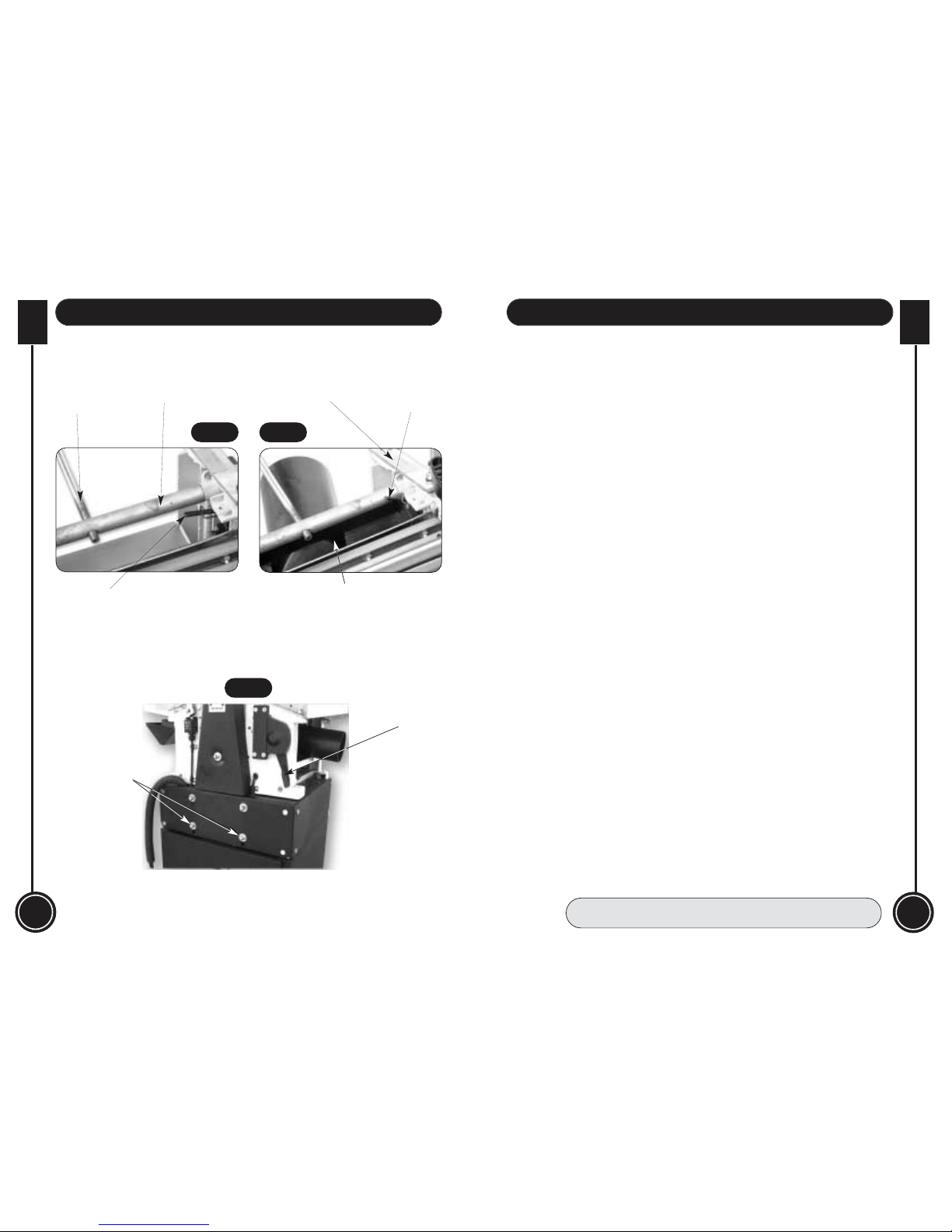
Identify the chip deflection cover and the 4 No. self-tapping screws and washers. Move to
the outfeed side of the machine and locate the aluminium extrusion mounted on the cross
bar in front of the anti-kick back fingers (See fig 5). Position the cover in the channel in the
extrusion and secure by screwing the self-tapping screws (with their washers), through the
pre-formed holes in the cover into the slot in the extrusion. The complete assembly should
be able to pivot around the cross bar, up and over the cutter block, or return into the void
above the edge of the thicknessing table (see fig 6).
Locate the handle, screw the projecting thread into the tapped hole in the crank arm as far
as the lock nut, tighten the lock nut down securely against the crank arm.
Open the Outfeed table clamps, (see fig 5). Raise the upper guard out of the way. Pivot the
chip deflector cover to the down position. Place the lugs of the outfeed table into the
machined rebates on the outfeed side of the machine. At the lower end of the mounting
lugs are two location brackets. The lower open slot in these location brackets fits over the
peg dowels screwed into the chassis (see fig 5). At the top end of the nearside lug is a
small bracket (see fig 7) that depresses a sprung stop that then allows the nearside
clamping lever to be turned to the clamped position. This in turn moves a sprung bobbin
which orientates a microswitch interlock to indicate the machine is in ‘Planer Mode’. Press
down firmly on the table, having ensured all the locators are positioned correctly, turn the
clamping levers to lock the table down.
The guide fence components come fully assembled, but not tightened. Unscrew the bolt to
enable it to be slid into the slot in the mounting, position where required and tighten the
lever handle. The fence is bolted to the support bracket by two coach bolts, washers and
nuts. The coach bolts fit into a ‘T’ slot moulded in the fence (see fig 15). Adjust the ‘fore and
aft’ position of the fence to the position required and secure by tightening the nuts, make
sure the “notch” on the underside of the fence straddles the cutter block (see fig 8).
Note. There is an electronic braking system on your machine, which works by
switching the ‘run’ capacitor. When you stop the machine after it has been running,
you will hear a “click, click” sound as the brake activates, and the motor will slow
down quite quickly. Please be aware that the effectiveness of the braking action is
dependent on the ‘run’ capacitor being fully charged; this takes a finite time after
the motor has been started.
If you start and then stop the machine very quickly, without allowing sufficient time
for the ‘run’ capacitor to charge fully, the switching occurs (i.e. you will hear the
clicking sound) but there is no apparent braking action.
Additional Note. To carry out the overhand planing operation; the interlocks are set
such that you require the dust extraction hood and the outfeed table fitted correctly.
1.Make sure you have read and fully understood the General Instructions and safety
precautions that are printed in the preceding pages of this manual.
2.Before connecting the machine to the supply; check for obvious signs of damage, paying
particular attention to the plug and the power cable. Rectify or have rectified any damage
you discover. Check the blades are not damaged; that they are clean and sharp. Change
the blades if necessary.
3. Set the thicknessing table to approximately 100mm and insert the dust extraction hood.
Raise the bed so that the hood is held in place and correctly operates the safety
microswitch as shown in figs 1 & 2. Connect up your dust extraction system (if available).
4. Set the fence, leaving sufficient exposed width of planer blades for you to machine the
largest dimension of the workpiece.
5. Check that all accessories, tools etc., which have been used to set the machine up, are
removed and set carefully aside or stowed away correctly.
6. Lower the infeed table to give the required cut, (e.g. maximum to work badly distorted or
very roughly finished timber, minimum to ‘finish’ a fine straight cut off a saw?). Put the
workpiece onto the infeed table and advance to the cutter block, set the upper guard to
‘just’ clear the workpiece, covering the whole of the exposed part of the cutter block.
7. Check the workpiece. Select the ‘face’. (The first planing operation). Ensure that, if
possible, you are not planing against the grain, and that if the stuff is bent, that the back of
the bow is uppermost.
8. Check (especially on site), that there are no foreign objects e.g. old nails, screws, small
stones etc. embedded in the material you are about to cut.
9. Ensure the function selector switch is set to off (‘0’). Plug the power cable into a
correctly rated switched socket outlet. If extension leads are being used, check these for
damage, do not use if damaged; if you are working outside, check that any extension
cables in use are rated for outside work.
Fitting the Guide Fence
The angle of the fence can be set between the preset 0 degree and 90 degree positions by
loosening the lever handle, adjusting to the angle required and re-tightening. There is a
scale embossed on the support bracket casting to give a guide to the angle you are setting
(see fig 14). The lever handles are the ‘lift’ to disengage type. e.g. if the lever is turned into
a position where it is fouling against the guide fence mounting bracket, pulling the handle
up on its shaft, against its spring keeper, will disengage the spline drive and can be moved
freely away from the obstruction. Allowing the handle to be sprung back will re-engage the
spline and the handle will again act as a lever.
Fitting the Infeed Table
The table should now be able to move, if it doesn’t, slacken a shade more. (Please note that
the adjusting movement is quite stiff, as the table lugs are captured with only a small
clearance to allow movement, but maintain rigidity when the machine is used in the
overhand mode. Keep the capping strip securing bolts as tight as is practically possible,
whilst allowing the table to move). Check the table moves up and down, at least between
the extreme marks on the setting scale, (remember you will have to take up the ‘slack’ when
you reverse direction of the table movement).

10
WHITE
AXMINSTER
W
WHITE
AXMINSTER
W
Illustration & Parts Description...
27
Setting Up the Machine...
FREEPHONE 0800 371822
Shaped cut out in
dust extraction hood
Actuated
microswitch lever
Capping strip
Cross bar
Infeed table
adjusting screw
Un-actuated
microswitch lever
Fig 1 Fig 2
Upper guard
assembly raise &
lower lever
Motor mounting
plate securing nuts
Fig 3
Setting up the Machine in the event of a Mishap
NOTE. The top edge of the planer blade should be in line with the top of the outfeed table,
and the infeed table when the infeed table is registered at zero cut.
The machine is ‘factory’ set, but if you have any doubts, or if, in the course of usage the
machine sustains a ‘knock’ et al., and you wish to check the basic parameters, proceed as
follows:-
Checking tables in plane
Adjust the infeed table to its highest limit against the register marks, fit the outfeed table.
Put an engineers’ straight edge (preferably 1000mm) along the tables and check that the
edge is in contact all along both tables, if it is not set the outfeed table to the infeed table.
Adjust the edge of the infeed table to the same height as the edge of the outfeed table
(across the cutter block). At the bottom of the locating lugs of the outfeed table are two
grub screws that will enable the outfeed table to be ‘tilted’ (see fig 7).
Loosen the outfeed table clamps, adjust the grub screws, tighten the clamps, check the
level. Proceed in this manner until the tables are in plane. If the tables are ‘in twist’, make or
use two ‘winding’ sticks, (two ‘sticks’ that have the same dimensions) stand one on each
table near the ends (across the table) sight across the two edges and see if they are
parallel, or the tables are ‘in wind’ to each other. (Note. The longer the sticks the greater the
amplification of the fault). Proceed as with getting the tables in plane, only this time adjust
the grubscrew at the relevant side of the table.
Setting the Guide Fence
Lock the guide fence in position on the table and upright. Check the heel of the casting is
hard up against the preset stop (see fig 15). Place an engineers’ square on the table and
move against the fence. If the fence is out of upright, loosen the fence, adjust the stop, put
the fence back to upright, tighten and check again. Proceed in this manner until the fence is
set correctly.
Check that the pointer is reading zero against the embossed scale, if not, check that the
guide fence mounting is correctly clamped to its mounting bracket. If it is, make a note or
mark to read the discrepancy between the pointer and the scale during future settings.
Loosen the fence and tilt to 45 degrees, check that the toe of the casting is hard against the
preset stop (see fig 15). Measure the angle of the fence with a bevel gauge or engineers’
combination square and check it is 45 degrees, if not, adjust the preset stop until the
correct angle is achieved. Check the pointer is reading correctly against the scale.

WHITE
AXMINSTER
W
11
Illustration & Parts Description...
FREEPHONE 0800 371822
26
WHITE
AXMINSTER
WIllustration & Parts Description...
www.axminster.co.uk
Infeed table adjusting
handle
Infeed table
adjusting screw
Guide fence
mounting bracket
Rise & fall handle for
thicknesser bed
Upper guard
slide lock
Outfeed table
clamps
Outfeed table
clamps
Peg dowel
Peg dowel
Aluminium
extrusion
Anti-kick
back fingers
Anti-kickback
fingers
Fig 4
Fig 5
Tilting action clamp
Tilt scale & pointer
Clamping bolt
Preset 45˚ stop
90˚ Preset
Typ. fore & aft
adjustment of
guide clamp
bolt
Infeed table adjusting
handle
Fig 14
Fig 15

WHITE
AXMINSTER
W
Illustration & Parts Description...
FREEPHONE 0800 371822
12
WHITE
AXMINSTER
WIllustration & Parts Description...
www.axminster.co.uk
Dust extractor
Chip deflector
Upper guard
assembly
Typ. threaded
corner spindle Thicknessing
depth scale
and pointer
Infeed table adjusting
handle
Sprung bobbin
Sprung stop
Microswitch
Actuating bracket
Adjusting grub screw
Dust extraction hood
Chip deflection
hood
Thicknesser feed
drive cover
Guide fence assembly
Dead space plate
Typ. outfeed
table clamp
Thicknesser bed rise
& fall crank
Infeed table
adjusting
knob
Fig 13
25
Fig 6
Fig 7

WHITE
AXMINSTER
W
13
Illustration & Parts Description...
FREEPHONE 0800 371822
24
WHITE
AXMINSTER
WIdentification & Description...
www.axminster.co.uk
Upper guard
assembly
Guide fence
Thicknessing bed rise and fall handle
Infeed table
Dust extractor
Main chassis
assemby
Function
selector switch
NVR buttons
Thicknessing bed
Drive belt cover
Infeed table
adjusting knob
handle
Upper guard rise
& lower lever
Outfeed table
Chip deflector
(closed position)
Cabinet stand
assembly
Fig 8
Thicknesser feed A moulded cover mounted on the off side of the main chassis, secured
drive cover by two domehead nuts.
(See Fig 13)
Dust extraction A moulded plastic hood with a 100mm dust extraction port. When
hood fitted in the void over the thicknessing table during the planing
(See Fig 13) operation, it acts as a guard to the underside of the cutter block, the
initiator of part of the interlock circuit, as well as collecting the chips and
shavings.
Chip deflection A moulded plastic hood fitted into an aluminium extrusion that is pivoted
hood on a cross bar in the main chassis assembly. During overhand planing
(See Fig 13) operations it is folded into the void above the thicknessing bed beneath
the outfeed table. During thicknessing operations, it is folded up and
over the cutter block to act as the upper guard; it also sets part of the
interlock circuit as well as deflecting the chips and shavings away from
the machine. It is moulded in such a way as to allow the dust extraction
hood to clip over it and form the dust extraction pathway for connection
to your dust extraction system.
Anti-kickback A series of shaped metal fingers mounted on a cross bar in the main
fingers chassis assembly, at the entrance to the thicknesser void. They are
(See Fig 5) shaped and pivoted such as to allow the entrance of the material onto
the thicknesser bed, but will not allow it to be withdrawn, or ‘kicked
back’ when it comes into contact with the cutter block. To overcome the
anti-kickback fingers, you have to lower the thicknesser bed to a degree
whereby the material could not be fed into the cutter block.
The function selector switch has three positions. The centre position
marked‘O’ is the OFF position. The position marked selects the
PLANING mode and the position marked selects the
THICKNESSING mode. Alongside the function selector are the NVR
(See Fig 9) Start/Stop buttons, beneath the “quick” action stop shroud. Standard
marking with ‘I’ indicating Start and ‘O’ indicating Stop.
Guide fence The guide fence is an aluminium extrusion and angled support bracket.
(See Fig 9) The whole assembly is bolted to the guide fence mounting bracket on
the side of the infeed table. The support bracket also mounts the ‘dead
space’ guard plate (the guard that covers that portion of the cutter block
behind the guide fence).
Function selector
switch and
NVR start/stop
buttons

14
WHITE
AXMINSTER
W
WHITE
AXMINSTER
W
Identification & Description...
23
Notes...
Stand assembly A preformed metal stand that encloses the motor. The main chassis
(See Fig 8) assembly is bolted to it. The whole is then bolted to the cabinet stand.
Main chassis The main body of the machine that all the other parts are mounted upon.
assembly
(See Fig 9)
Infeed table The infeed table adjusting screw is held captive in a ring casting on the
adjusting front underside of the infeed table. It is a long length of rod with a
screw handle moulded on one end and a thread cut on the other. The threaded
(Unseen) part of the rod engages in a tapped hole in a cross bar of the main
chassis. Because the adjusting screw is held captive in the infeed table,
screwing the rod backwards and forwards will move the infeed table
backwards and forward on its slideways on the main chassis.
Infeed table The table that supports the material on the input side of the machine. It
(See Fig 8) moves up and down in a pair of inclined slideways machined in main
chassis, the level of the table is set relative to the top of the planer irons;
this setting governs the depth of cut that can be taken during the
overhand planing operation. The guide fence mounting bracket is
attached to the infeed table.
Thicknessing bed This handle is fitted to a crank arm formed on one of the threaded
rise and fall spindles that carry the thicknessing bed. There are four threaded
handle spindles that are connected by a chain drive in the lower part of the
(See Fig 9) main chassis assembly. The chain drive is tensioned by an idler gear,
which should be checked periodically.
Outfeed or The table that supports the work after it has passed over the cutter block
take off table during the overhand planing operation. The level of the table is set to be
(See Fig 9) in line with the top of the plane irons, thus once the cutting action is
finished the table will support the workpiece during the remainder of the
planing pass. The outfeed table is removed for thicknessing operations,
to allow better access to the material passing over the thicknessing bed.
Upper cutter An aluminium extrusion covers the cutter block. It can be positioned
block guard both in height and laterally. It is mounted in a housing at the top of the
assembly support leg. The support leg has a rack machined into it which engages
(See Fig 9) with a pinion moulding which has a lever extrusion. Moving the lever up
and down will drive the support leg up and down, thus varying the height
of the upper guard. The guard mounting housing has a clamp set in it
which enables the guard to be clamped laterally.
Outfeed table These are the two clamps set on each side of the main chassis that
clamps clamp the outfeed table in position during the overhand planing
(See Fig 9) operation. The offside clamp position is also critical, in that it is part of
the interlock sequence, care must be taken to ensure the correct
configuration is met whilst setting the machine up for planing or
thicknessing. See the Operating Instructions.
Drive belt cover A moulded cover mounted on near side of the main chassis, secured by
(See Fig 8) a domehead nut.

22
WHITE
AXMINSTER
W
WHITE
AXMINSTER
W
Illustrated Parts List (Part 2)...
15
Illustration & Parts Description...
FREEPHONE 0800 371822
Outfeed table Guide fence
Thicknessing bed rise and fall handle
Capping Strip
Infeed table
Stand assembly
Main chassis assembly
Typ. outfeed
table clamp
Stop start NVR buttons
Upper cutter
block guard
assembly Infeed scale
and index
mark
Overhand symbol
Function selector switch
Thicknessing symbol
Fig 9

16
WHITE
AXMINSTER
W
WHITE
AXMINSTER
W
Illustrated Parts Breakdown...
21
Illustrated Parts List (Part 1)...
Fig 10

20
WHITE
AXMINSTER
W
WHITE
AXMINSTER
W
Illustrated Parts Breakdown...
17
Illustrated Parts Breakdown...
Fig 12
Stand

18
WHITE
AXMINSTER
W
WHITE
AXMINSTER
W
Illustrated Parts Breakdown...
19
Illustrated Parts Breakdown...
Fig 11
Other manuals for AWEPT106
1
Table of contents
Other Axminster Planer manuals