04
General Instructions for 230V Machines
cutters and blades or when making any adjustments.
• Before using any machine or power tool, ensure that
all locking-nuts, chucks etc, are tightened and secure.
Check that all loose keys, spanners and other tools have
been removed.
• Always check that the correct machining or cutting
speed has been selected.
• Do not operate machinery or power tools when tired
or under the influence of alcohol, drugs or certain
medicines.
• Always ensure that long hair is tied back or retained
by a band, hat or safety helmet. Remove all loose
jewellery to prevent it from catching in rotating parts
of the machine.
WHEN USING MACHINES ALWAYS WEAR SUITABLE EYE PROTECTION,
EAR DEFENDERS AND DUST OR FUME INHALATION PROTECTION.
WARNING!! KEEP TOOLS AND EQUIPMENT OUT OF THE REACH OF
CHILDREN, UNLESS THEY ARE UNDER SUPERVISION.
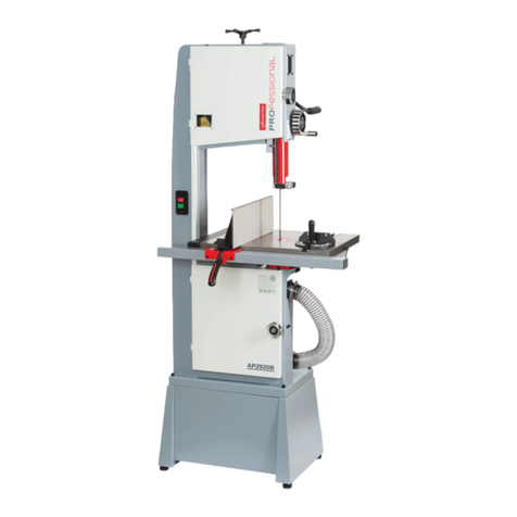
Specific Safety Instructions for Bandsaws
• Use only the correct size of blade for the machine.
Ensure that the blade is sharp and that the blade
support clearances, blade tension and tracking are all
correct. Blunt and/or in-correctly set blades require
more force and make control of the work more
difficult, leading to the possibility of accidents.
• Ensure that the blade guard and top bearing
assembly is as close to the top of the work as possible.
This will both support the blade correctly and ensure
that minimum amount of blade is exposed.
• Ensure that the table and fence, if used, are fully
tightened and cannot move under load.
• Push sticks or push pads should always be used when
cutting wood on a bandsaw. If necessary, one push
stick should be used to push the wood through the
blade and another used to hold the timber up against
the fence.
• Ensure that the blade has completely stopped before
removing small scraps of wood from the table.
• Only saw timber which is lying flat on the table; work
which is curved in the vertical plane should be fully
supported along its length in a suitable jig.
• When tight curves are being cut there is a risk of the
blade jamming in the slot in the timber. Use a narrow
blade when cutting tight curves.
