manuals.online logo
Brands
  1. Home
  2. •
  3. Brands
  4. •
  5. Axminster
  6. •
  7. Saw
  8. •
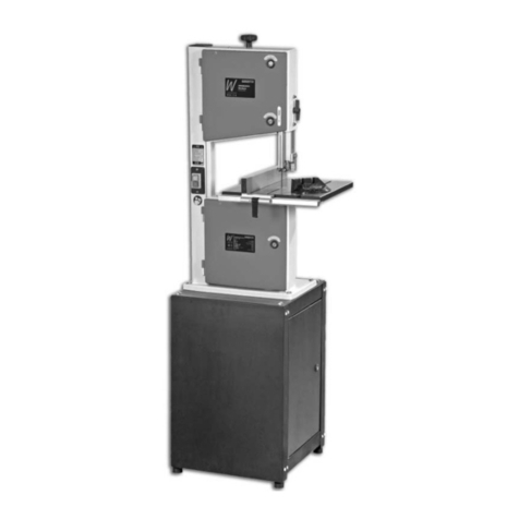
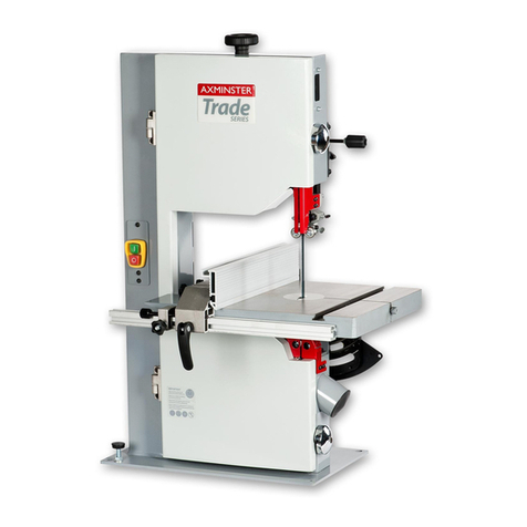
  9. Axminster WORKSHOP AW1400B User manual

Axminster WORKSHOP AW1400B User manual

AW1400B
Bandsaw
Code 107710
Original Instructions
AT: 22/07/2022
BOOK VERSION: 10
INDEX OF CONTENTS
2
EU DECLARATION OF CONFORMITY
EU Declaration of Conformity 02
What’s Included 03-04
General Instructions for 230V Machines 05-06
Specification 06
Assembly 06-07-08
Illustration and Parts Description 09-10-11-12-13
Setting Up the Saw 14-15-16-17-18-19
Operating Instructions 19-20
Changing the Saw Blade 20-21
Routine Maintenance 22
Machine Footprint 23
Bandsaw Blade Information 24-25
AW1400B Bandsaw Blades 26
Bandsaw Trouble Shooting/Accessories 26
UJK Technology Bandsaw Buddy 27
Exploded Diagrams/Lists 28-29-30-31
Wiring Diagram 31
Cert No: MJ3420, MJ3425,
MJ343C, MJ343B
Axminster Tool Centre Ltd
Axminster Devon
EX13 5PH UK
axminstertools.com
Type Bandsaw
Model AW1400B conforms to the machinery example for which the
EC Type-Examination Certificate No BM 50421300
has been issued by Laizhou Fulin Machinery Co., Ltd.
at:Wenchang Road Street Nanwuli Industry Yard
Laizhou, Shandong261400 China
and complies with the relevant essential health and safety requirements.
2006/42/EC
2004/108/EC
EN 1807-1:2013
EN 60204-1:2006+A1+AC
declares that the machinery described:-
This machine complies with the following directives:
EU Declaration of Conformity
06/42/EC - Annex I/05.2006
Signed
Andrew Parkhouse
Operations Director Date: 05/11/2018
Fully read manual
and safety instructions
before use
Eye protection
should be worn
Ear protection
should be worn
HAZARD
Motor gets hot
Dust mask
should be worn
The symbols below advise the correct safety procedures when using this machine.
WHAT’S INCLUDED
3
Quantity Item Part Model Number
AW1400B
1 Craft Bandsaw A
1 Bandsaw Blade 1,400mm Long 6mm 6TPI
(Mounted on the saw but not tensioned)
1 Table B
1 Fence Rail C
1 Fence Assembly D
1 Mitre Fence (Optional Accessory) E Code: 102919
1 Push Stick F
1 Fence Rail Scale Strip (see pages 17-19 for mounting instructions)
Fixings
4 M6 x 12mm Caphead Screws G
4 M6 Washers H
4 M8x12mm Bolts I
4 M8 Washers J
1 Angled Bolt and Nut K
1 3-4mm Hex Key L
4 Adjustable Rubber Feet M
1 Instruction Manual
Having unpacked your saw (see below) and its accessories please dispose of any unwanted packaging
properly.The cardboard packaging is biodegradable.
A
B
M
WHAT’S INCLUDED
4
F
C
D
L
J
HI G
E
Optional Mitre Fence
Code: 102919
K
GENERAL INSTRUCTIONS FOR 230V MACHINES
5
The following will enable you to observe good
working practices, keep yourself and fellow workers
safe and maintain your tools and equipment in good
working order.
Mains Powered Tools
•Tools are supplied with an attached 13 Amp plug.
•Inspect the cable and plug to ensuree that neither
are damaged.Repair if necessary by a suitably
qualified person.
•Do not use when or where it is liable to get wet.
Workplace
•Do not use 230V a.c. powered tools anywhere
within a site area that is flooded.
•Keep machine clean.
•Leave machine unplugged until work is about to
commence.
•Always disconnect by pulling on the plug body
and not the cable.
•Carry out a final check e.g. check the cutting tool.
is securely tightened in the machine and the
correct speed and function set.
•Ensure you are comfortable before you start work,
balanced,not reaching etc.
•Wear appropriate safety clothing, goggles, gloves,
masks etc.Wear ear defenders at all times.
•If you have long hair wear a hair net or helmet to
prevent it being caught up in the rotating parts of
the machine.
•Consideration should be given to the removal of
rings and wristwatches.
•Consideration should also be given to non-slip
footwear etc.
•If another person is to use the machine, ensure they
are suitably qualified to use it.
•Do not use the machine if you are tired or distracted
•Do not use this machine within the designated
safety areas of flammable liquid stores or in areas
where there may be volatile gases.
•Check cutters are correct type and size,are
undamaged and are kept clean and sharp, this will
maintain their operating performance and lessen
the loading on the machine.
•
OBSERVE….
make sure you know what is
happening around you and
USE YOUR COMMON
SENSE.
WARNING!! KEEP TOOLS AND
EQUIPMENT OUT OF REACH OF
YOUNG CHILDREN
KEEP WORK AREA AS
UNCLUTTERED AS IS
PRACTICAL. UNDER NO
CIRCUMSTANCES SHOULD
CHILDREN BE ALLOWED IN
THE WORK AREA.
SPECIFICATION
6
Code 107710
Model AW1400B
Rating Workshop
Power 250W 230V 1ph
Blade Speed 800 m/min
Blade Length 1,400 mm
Blade Width Min/Max 6 mm to 9.5 mm
Max Width of Cut 200 mm
Max Depth of Cut 80 mm
Max Width of Cut with Fence 102 mm
Airflow 200 m3/hr
Table Size 300 x 300 mm
Table Tilt 0-45°
Table Height 290 mm
Wheel Diameter 200 mm
Dust Extraction Outlet 40 mm
Overall L x W x H 450 x 430 x 700 mm
Weight 20 kg
Please read the Instruction Manual prior to using your new machine; as well as the operating procedures for
your new machine,there are numerous hints and tips to help you to use the machine safely and to maintain
its efficiency and prolong its life.
Keep this Instruction Manual readily accessible for any others who may also be required to use the
machine.
NOTE:The table can be fitted without removing the
bandsaw blade. However, if you feel safer with the
bade removed, loosen the blade tensioning knob
(A),see fig 01 and very carefully remove the blade. To
refit the blade refer to pages 18-19 for “Changing the
Saw Blade”.
Fitting the Table
Fitting the Rubber Feet
WARNING! WE ADVISE YOU
WEAR GLOVES AS THE BLADE
HAS SHARP TEETH!
ASSEMBLY
Locate the four adjustable rubber feet (M), screw
each foot in turn into each corner to the underside of
the bandsaws base,see fig A & B. Stand the bandsaw
upright, adjust each foot until the bandsaw is level.
Nip-up the locking nuts against the frame to secure
in position.
B
A
Thread rubber foot
Locking nut Mounting
bracket
ASSEMBLY
7
Fig 02
Fig 01
Step 1 Locate the bandsaw table (B), the four M6
caphead screws (G) and washers (H). Slot the blade
into the table’s slot and line up the threaded holes
in the table with the pre-drilled holes on the tilt
quadrant, see fig 02.
Step 2 Place a washer (H) over each M6 caphead
screw (G),screw the caphead screws through the
tilt quadrant into the table and tighten using the
supplied spanner, see fig 03.
Fig 03
HH
GG
Step 1 Locate the fence rail (C), fence assembly (D),
four M8 bolts (I) and washers (J). Place a washer over
the end of each bolt and lightly screw the bolts into
the threaded holes beneath the front of the table (B),
see fig 04. NOTE: Leave sufficient distance between
the bolt head and table for mounting the fence
rail.
Fitting the Fence
Fig 04
JJ
II
Step 2 Find the fence rail (C), line up the half moon
cutouts with the four bolts in the table and insert the
fence rail up against the table (B), see fig 05.
Fig 05
Continues Over...
CC
Secure the fence rail (C) in position by tightening the
four bolts with the supplied spanner, see fig 06.
Fig 06
AA
BB
ASSEMBLY
8
Fig 08
Fig 07
DD
Fence rail“T” slot
Clamping lever
Step 4 Locate the angled bolt (K), screw the
threaded end of the bolt into the threaded hole to
the top of the bandsaw frame and, using the supplied
10mm spanner, tighten with the nut to lock the bolt
in position, see fig 09. Find the push stick (F) and
hook it onto the angled bolt (K), see fig 10.
Fig 09-10
Fig 11
F
K
Table“T” slot EE
Step 3 Locate the fence assembly (D).Lower the
fence over the table until the clamping lever
assembly slots into the fence rail’s “T” slot. NOTE:
Make sure the clamping hook to the rear of the
fence (D) has engaged over the rear of the table.
Twist the locking lever clockwise to adjust the
clamping tension.(two rotations should be adequate)
then press down the lever to lock the fence in
position, see figs 07-08.
Step 5 Locate the optional mitre fence assembly (E)
and slide it into the table’s “T” slot, see fig 11.
ILLUSTRATION AND PARTS DESCRIPTION
9
Lower wheel door
Guide fence
Upper door locking knob
Lower door locking knob
Upper blade guide and guard
Fence guide rail
Saw table‘T’ slot for mitre fence
ON/OFF buttons
Upper wheel door
Blade tensioning knob
Blade
Table insert
ILLUSTRATION AND PARTS DESCRIPTION
10
Optional mitre fence assembly (A)
Index and pointer (B)
Blade guide adjusting knob (A)
Blade guide clamp (B)
Blade tensioning knob
Table levelling stop bolt
Tracking control knob (A)
Tracking control butterfly lock (B)
Tilt quadrant (A),Tilt scale (B)
Tilt scale pointer and adjusting screw (C)
ON/OFF NVR switch assembly
ON
OFF
AA
BB
A
A
C
B
A
B
BB
ILLUSTRATION AND PARTS DESCRIPTION
11
Upper blade guide clamp
Upper blade guide
adjusting knob
Saw table
Tilt mechanism
Tilt mechanism clamp
Motor air vents
Motor assembly
Main saw frame
Power cable
Tracking control
knob and lock
ILLUSTRATION AND PARTS DESCRIPTION
12
Lower blade guide assembly (A)
Guide bearing & adjustment caphead bolt (B)
Guide bearing locking grub screws (C)
Rear thrust bearing & clamping bolt (D)
Guide assembly fore and aft clamping bolt (E)
Blade tensioning spring (A),
under tension
Blade tensioning spring (B)
with no tension applied
Upper blade guide assembly (A)
Guide bearing locking grub screws (B)
Guide bearing adjustment caphead bolts (C)
Rear thrust bearing and clamping bolt(D)
Guide assembly fore and aft clamping bolt (E)
Twist the locking lever clockwise to adjust the clamping
tension, (Two rotations should be adequate) then press
down the lever to lock the fence in position.
DD
CC
EE
DD
AABB
B
C
AA
EE
BB
A
Increase tension
Decrease tension
ILLUSTRATION AND PARTS DESCRIPTION
13
Lower saw wheel
Fence clamping lever
Dust extraction outletSaw wheel brush
Upper saw wheel
Upper door micro switch
Lower door micro switch
Upper wheel mounting
Blade guide assembly
Saw table slot
SETTING UP THE SAW
14
DISCONNECT THE SAW FROM
THE MAINS SUPPLY!
DISCONNECT THE SAW FROM
THE MAINS SUPPLY!
Tensioning and tracking the blade
Make sure both top and bottom blade guide
are well clear of the blade.
Open the front covers fully, giving good access to
the top compartment of the saw and good visibility
into the bottom compartment, see page 13. For
tracking the blade first adjust all bearing guides so
that they’re well clear of the blade. Check that the
blade is sitting approximately in the middle of the
wheels, see fig 12.
Apply some tension to the blade by turning the
tensioning wheel clockwise. Spin the top wheel by
hand, and check that the blade remains centrally on
the tyre, see fig 13. If it does not, loosen the tracking
control lock and adjust the tracking by turning the
tracking control at the rear of the upper saw wheel
compartment, see fig 14. Viewed directly onto the
tracking control wheel, turning clockwise should
cause the blade to track to the rear of the tyre,
anti-clockwise to the front (DO NOT make large
adjustments).
Spin the top wheel again, check again. Continue
until the blade tracks in the centre of the tyres with
no appreciable to and fro movement. Tension the
blade fully. A sideways push on the blade should
allow a maximum of 1 centimetre of movement
with moderate pressure on the blade. Check the
tracking again, adjust if necessary.
Connect the power to the machine. Stand clear and
start the saw,check that the saw is running smoothly,
(no thumps, bumps,knocking or excessive vibration)
and the blade appears to be tracking correctly (in
one place).You can check this by holding a marker
e.g. a pencil, close to the back of the blade (approach
from the back of the blade only) and check that the
gap remains constant. If it doesn’t, adjust the tracking
until it does. If you adjust the tracking with the saw
running,make very small adjustments and wait for
the saw to react before you adjust again, sometimes
the reaction is not instantaneous. Once you are
satisfied that the tracking is correct switch the
machine off and allow it to run to a stop. Retighten
the tracking control lock.
Fig 12
Blade
Tyre
Fig 13
Fig 14
Tracking control lock
Tracking control
SETTING UP THE SAW
15
Checking the table is square
If the preset table stop has been fitted, proceed as
follows:-
Loosen the lift and shift handle clamping the tilt
mechanism, see fig 15, and turn the table hard
against its stop.This is a bolt with a lock nut screwed
into the underside of the table,see fig 16, that acts as
a stop when it strikes the machine frame.Tighten the
butterfly nut.
Fig 15-16
Lift & Shift Handle
Make sure the upper blade guide is raised as high as
possible. Place a square on the table and move it up
against the blade (behind the teeth), see fig 17.
Fig 17
Check that the blade is perpendicular to the table. If it
is not, try resetting the table.
If it is still not correct, loosen the locking nut and
adjust the bolt until perpendicularity is achieved, see
fig 16. Tighten the lock nut and then re-check.When
you are satisfied that the table is set correctly, check
that the pointer of the tilt gauge reads zero,if not,
adjust it, see fig 18.
Locking nut
Fig 18
Tilt pointer (A) and tilt gauge (B)
A
B
Setting the Fence
Always make sure the fence is parallel to the table
by placing an engineer’s rule against the fence and
setting equal distances to the front and back face of
the fence, see figs 19-20.
Continues Over...
Fig 19-20
‘T’ slot
Front face
Back face
SETTING UP THE SAW
16
Setting the Blade Guides
Lower the upper blade guide to approximately 1
1/2”(38mm) above the table by loosening the blade
guide height clamp and turning the adjusting knob.
Clamp in place,see figs 21-22. Loosen the bolt (A)
holding the guide assembly in place, see fig 23.
Adjust the fore or aft position so that the leading
edges of the side guide bearings are approximately
2mm behind the gullets of the saw blade. Re-tighten
the clamping bolt, see figs 24-25.
Fig 21-22
Fig 23
AA
Fig 24-25
2mm
38mm
Blade guide clamp
Adjusting knob
Steel rule
Guide Bearings
Guide assembly
Fig 26
1mm behind the blade
Loosen the bolt (B) that clamps the rear thrust
bearing and move the thrust bearing so it’s 1mm
behind the blade; re-tighten the clamping bolt, see
fig 26. Turn the blade by hand to check the thrust
bearing turns. Loosen the two grub screws to the rear
of the guide assembly, see fig 26. Using a Hex key
move the bearings (D), approximately 0.5mm from
each side of the blade, see fig 27. Re-tighten the grub
screws to lock the bearing in place.
DISCONNECT THE SAW FROM
THE MAINS SUPPLY!
BB
Guide Bearing
clamping grub
screw
SETTING UP THE SAW
17
Setting the Fence Scale
Fig 27
Setting the Lower Blade Guides
NOTE: For easier access to the lower blade guides
it is recommended you remove the table.
Open the lower wheel access door and the lower
blade guard door, see fig 28. Repeat the procedures
as described for the upper blade guides and
thrust bearing, see fig 29. Once all adjustments are
completed rotate the blade, replace the table and
close the blade guard door.
NOTE: MAKESURE THE TABLE
AND FENCE IS SQUARE TO THE
BLADE!
Fig 28-29
Fig 30
Fig 31
Close the upper and lower doors, re-connect the
power, switch the saw on, allow to run for several
minutes, check that the blade is still tracking
correctly, there is no excessive vibration, etc.Switch
off and wait until the saw comes to a complete stop.
The saw is ready to be used.
Lower guide Bearing
Continues Over...
DD
Lower thrust bearing
The fence scale strip does not come pre-mounted to
the fence rail and need to be stuck in place. NOTE:
Before sticking the scale down makesure the table
and fence assembly is square to the blade. Follow
the instruction below.
1) Place a square against the blade & adjust the table
until it’s square to the blade.
2) Position the fence against the bandsaw blade and
lock in place.
SETTING UP THE SAW
18
Fig 32 Fig 35
Fig 36-37Fig 33-34
3) Check the fence is square to the table. 5) Using a pencil, ‘MARK’ the position on the guide
fence rail.Remove the fence assembly.
6) Peal off the backing from the scale strip, line-up the
‘ZERO’ line with the pencil ‘MARK’ and carefully stick
down the strip onto the fence rail.
4) Using a steel rule check the fence is still in-line with
the cast iron table.
Scale ‘ZERO’ line
Pencil mark
SETTING UP THE SAW
OPERATING INSTRUCTIONS
19
1. Make sure you have read and fully understood the
general instructions and safety precautions that are
printed in the preceding pages of this manual.
2. Before connecting the machine to the supply;
check the tool for obvious signs of damage, paying
particular attention to the plug and the power cable.
Rectify or have rectified any damage you discover.
Check that the blade you are using is the correct one
for the job in hand. Change the blade if necessary.
Check the blade is not damaged; is clean, sharp,
tracks properly and is correctly tensioned.
3. Set the upper blade guide to approximately 12mm
(1/2”) above the height of the work piece.
4. Check, especially on site, that there are no foreign
objects e.g. old nails, screws, small stones etc.
embedded in the material you are about to cut.
5. Check that all accessories, tools etc.,that have been
used to set the machine up, are removed and set
carefully aside or stowed away correctly.
6. Ensure the machine is switched off. Plug the
power cable into a correctly rated switched socket
outlet. If extension leads are being used, check
these for damage,do not use if damaged; if you are
working outside, check that any extension cables in
use are rated for outside work. Switch on. Allow the
saw to run up to speed.
7. Make sure that the material you are about to cut
is within the machine capacity, and the cut you are
about to make is within the blade’s capabilities. e.g.
Do not try to cut a 1”radius curve using a 5/8”blade.
8. Make sure the blade is not in contact with the
material when you start the saw. Start the cutting
operation.
UNDER NO CIRCUMSTANCES
SHOULD CHILDREN BE ALLOWED IN
THE WORK AREA AND KEEP TOOLS
AND EQUIPMENT OUT OF REACH OF
YOUNG CHILDREN!
CONNECT A DUST EXTRACTION
MACHINE TO THE SAW.
Fig 38 Fig 39
7) Place the fence back on the table and up against the blade, lock in place. The fence should be alligned with
the ‘ZERO’ line on the scale.
OPERATING INSTRUCTIONS
20
CHANGING THE SAW BLADE
DISCONNECT THE SAW
FROM THE MAINS SUPPLY!
Put the table back to the level position if it has been
tilted.Set the upper blade guide assembly
approximately midway in the throat.Open the top
and bottom covering doors. Remove the fence and
guide rail and place safely aside. Slacken the blade
tension by turning the blade tensioning wheel
anti-clockwise, until the blade can be easily slipped
off the wheels, see fig 30.
Remove the blade carefully,“wriggling”it clear of the
upper blade guard,and out through the slot in the
table. NOW is an excellent time to clean out the
interior of the machine, remove the impacted ‘crud’
from the tyres, apply a little light oil to the screw
Fig 30
Slacken the blade by turning the
tensioning wheel anti-clockwise
threads of the blade tensioner, and the tracking
control.The pivots and the slides of the top wheel
WARNING! IF THE SAW JAMS!
SWITCH OFF IMMEDIATELY.
USE THE SUPPLIED PUSH STICK
WHEN CUTTING SMALL PIECES.
Do not try to cut too quickly; the correct cutting
speed, if one could be so precise, would never see
the blade pushed back against the thrust bearing.
The saw would cut and clear the saw line at the rate
the work piece was fed into it. If you notice that you
require more and more pressure to effect the cut,
and the blade is in continual contact with the thrust
bearing, the chances are the blade is becoming blunt.
Check and change if necessary.
Do not let go of the work piece; if you have to change
your grip, make sure one hand is holding the material
at all times.
9. If you are cutting long pieces of material think
about sawing cutouts (i.e.a saw cut from the edge
of the material to the saw line) along the saw line
so that you can discard the off cuts as you progress
down the saw line.
10. Observe the old woodworkers’ adage of never
allowing your hand/fingers within one handbreadth
of the blade.
11. If you have to cut very small pieces of material,
arrange or manufacture some form of ‘shoe’ to carry
the timber. If the work piece is exceptionally small,
find something to use as a sacrificial carrier and
mount the work piece on it with double sided tape,
or similar.
12. Remember to check the blade tension after a
new blade has been ‘working’ for 30-60 mins.The
blade will ‘stretch’ slightly when new.
13. Do not release the tension on the saw blade
when work is complete.The blades and the main
saw frame do not respond kindly to frequent large
changes in stress and tension. Only release the
tension to change the blade or if the blade is to be
removed because the machine is to be‘mothballed’
for a lengthy time period. The blade in tension over
a long period of non-use will cause the tyres to
develop ‘flat’ spots.
14. Open the saw cut, either by pulling apart or
driving a wedge in close to the back of the blade.
Try to “wriggle”the blade free of the saw. If this is not
possible; check that the saw is free in the cut, start
the saw, allow it to run up to speed and ‘cut out’ as
quickly as possible. The removal of the‘off cut’ may
well prevent the saw jamming again if you resume
the original cut.

This manual suits for next models

1

Other Axminster Saw manuals

Axminster UE-127DV1 User manual

Axminster

Axminster UE-127DV1 User manual

Axminster Trade AT3327B User manual

Axminster

Axminster Trade AT3327B User manual

Axminster AWSMS10 User manual

Axminster

Axminster AWSMS10 User manual

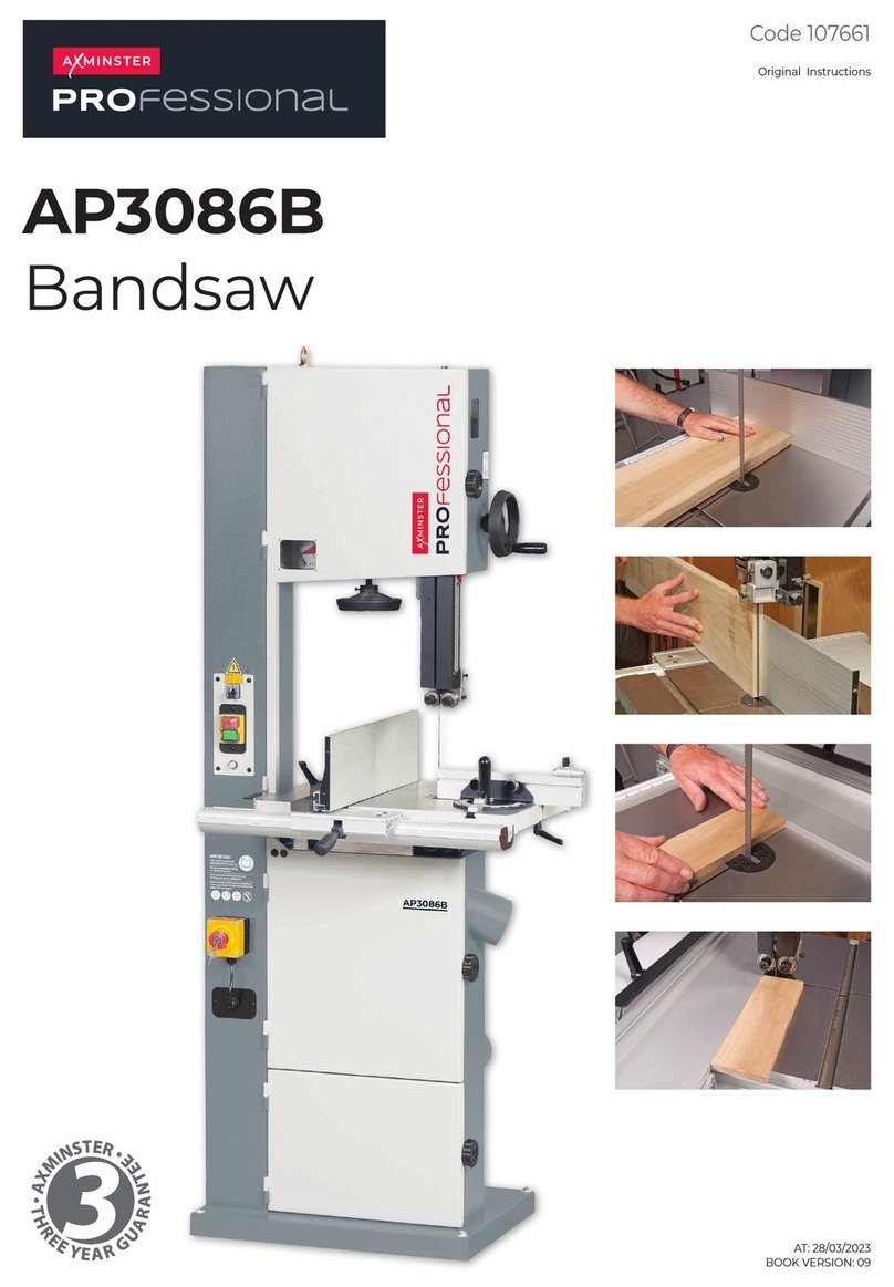
Axminster Professional AP3327B User manual

Axminster

Axminster Professional AP3327B User manual

Axminster Excalibur EX-16 User manual

Axminster

Axminster Excalibur EX-16 User manual

Axminster TS-200 User manual

Axminster

Axminster TS-200 User manual

Axminster AP3352B User manual

Axminster

Axminster AP3352B User manual

Axminster WorkShop AW2305B User manual

Axminster

Axminster WorkShop AW2305B User manual

Axminster TS-250M User manual

Axminster

Axminster TS-250M User manual
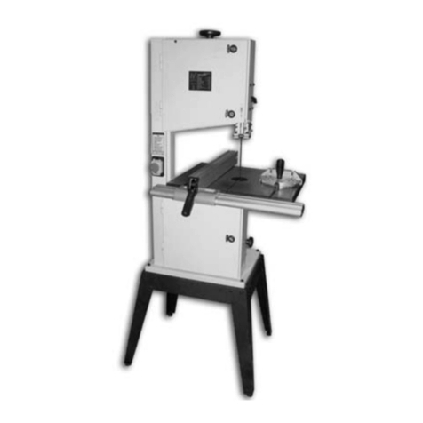
Axminster AC1950B User manual

Axminster

Axminster AC1950B User manual

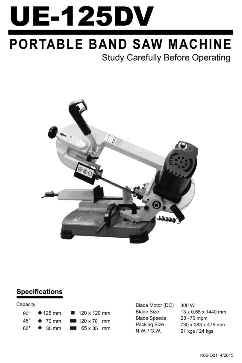
Axminster Excalibur EX-21 User manual

Axminster

Axminster Excalibur EX-21 User manual

Axminster AT254TS User manual

Axminster

Axminster AT254TS User manual

Axminster WorkShop AW1950B User manual

Axminster

Axminster WorkShop AW1950B User manual

Axminster Professional AP2552B User manual

Axminster

Axminster Professional AP2552B User manual

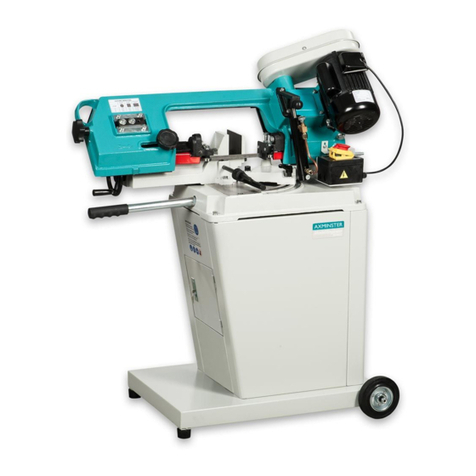
Axminster MCB210HD User manual

Axminster

Axminster MCB210HD User manual

Axminster AT3352B User manual

Axminster

Axminster AT3352B User manual

Axminster AWMS10 User manual

Axminster

Axminster AWMS10 User manual

Axminster AW405FS User manual

Axminster

Axminster AW405FS User manual

Axminster AW405SS User manual

Axminster

Axminster AW405SS User manual

Axminster UV-180DS User manual

Axminster

Axminster UV-180DS User manual

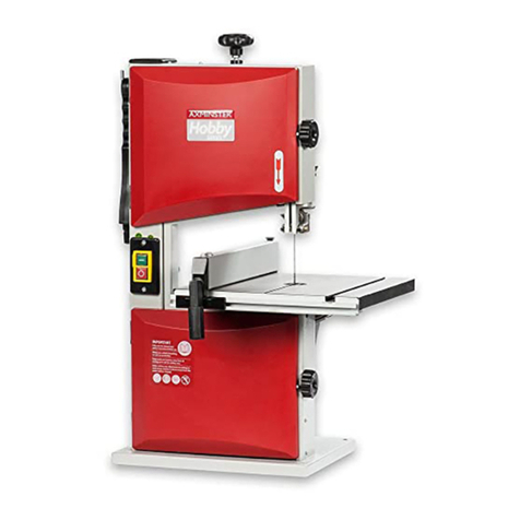
Axminster Hobby MS210S User manual

Axminster

Axminster Hobby MS210S User manual

Axminster PROFESSIONAL AP2920B User manual
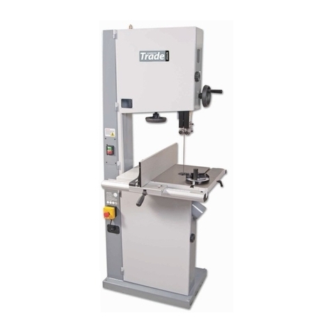
Axminster

Axminster PROFESSIONAL AP2920B User manual

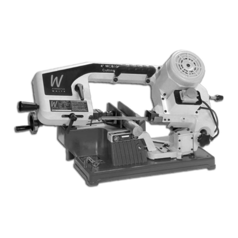
Axminster MCB100A User manual

Axminster

Axminster MCB100A User manual

Axminster HBS200N User manual

Axminster

Axminster HBS200N User manual
Popular Saw manuals by other brands

Stanley FATMAX FME380 Original instructions

Stanley

Stanley FATMAX FME380 Original instructions

KRESS 1500 KS operating instructions

KRESS

KRESS 1500 KS operating instructions

IMER C 350 i-Power Operation, maintenance, spare parts manual

IMER

IMER C 350 i-Power Operation, maintenance, spare parts manual

Genesis GMSDR1015LC Operator's manual

Genesis

Genesis GMSDR1015LC Operator's manual

Jula 243010 operating instructions

Jula

Jula 243010 operating instructions

Norton BBL547 owner's manual

Norton

Norton BBL547 owner's manual

skilsaw SPT44 Operating/safety instructions

skilsaw

skilsaw SPT44 Operating/safety instructions

HIKOKI C 1806DA Handling instructions

HIKOKI

HIKOKI C 1806DA Handling instructions

Jet HBS-56S Operating instructions and parts manual

Jet

Jet HBS-56S Operating instructions and parts manual

Scotchman CPO-315-HFA-CNC manual

Scotchman

Scotchman CPO-315-HFA-CNC manual

PrimeCables Cab-CCS326 user manual

PrimeCables

PrimeCables Cab-CCS326 user manual

EINHELL PTK 800 operating instructions

EINHELL

EINHELL PTK 800 operating instructions

Makita 5017RKB user manual

Makita

Makita 5017RKB user manual

Triton TR201781 Operating and safety instructions

Triton

Triton TR201781 Operating and safety instructions

Dust Director DD10 Operating and installation

Dust Director

Dust Director DD10 Operating and installation

AEG M18 CBS125 Original instructions

AEG

AEG M18 CBS125 Original instructions

Black & Decker BT1400 instruction manual

Black & Decker

Black & Decker BT1400 instruction manual

APT SAW 16 Safety & Operating Instructions

APT

APT SAW 16 Safety & Operating Instructions

manuals.online logo
manuals.online logoBrands
  • About & Mission
  • Contact us
  • Privacy Policy
  • Terms and Conditions

Copyright 2025 Manuals.Online. All Rights Reserved.