Axon Body 3 AX1026 User manual

Axon Body 3 Dock
Installation Manual
Models AX1026 and AX1027
Document Revision: C
June 2020

Axon Body 3 Dock Installation Manual
Axon Enterprise, Inc. Page 2 of 25
, AXON, Axon, Axon Body 3, Axon Body 3 Dock, Axon Device Manager, and Axon Evidence are trademarks of
Axon Enterprise, Inc., some of which are registered in the US and other countries. For more information, visit
www.axon.com/legal.
All rights reserved. ©2020 Axon Enterprise, Inc.

Axon Body 3 Dock Installation Manual
Axon Enterprise, Inc. Page 3 of 25
Table of Contents
Introduction to the Axon Body 3 Dock.....................................................................................................4
Axon Body 3 Dock Types...........................................................................................................................4
Additional Materials...................................................................................................................................5
Axon Body 3 Dock Information ................................................................................................................5
Network Considerations and Configuration ...........................................................................................7
Axon Body 3 Cameras and Network Infrastructure ..............................................................................7
Network Requirements .............................................................................................................................8
Firewall Configuration ...............................................................................................................................8
Axon Body 3 Dock Installation...................................................................................................................9
Dock Registration .....................................................................................................................................10
Wall Mounting an Axon Dock ..................................................................................................................11
Safety Instructions ...................................................................................................................................11
Tools and Materials..................................................................................................................................11
Dimensions ...............................................................................................................................................12
Installation.................................................................................................................................................12
Step 1: Preparation ..........................................................................................................................12
Step 2: Attach the Dock to the Wall Mount Bracket ....................................................................12
Step 3: Identify Dock Placement ....................................................................................................13
Step 4: Attach the Wall Mount Bracket to the Wall (Stud mount) .............................................13
Step 5: Attach the Wall Mount Bracket to the Wall (Drywall Mount) ........................................14
Step 6: Connect the Cables.............................................................................................................14
Troubleshooting and Other Information ...............................................................................................16
Technical Support ....................................................................................................................................16
Warranty Policy.........................................................................................................................................16
Warnings .................................................................................................................................................... 17
Compliance Marks ...................................................................................................................................25

Axon Body 3 Dock Installation Manual
Axon Enterprise, Inc. Page 4 of 25
Introduction to the Axon Body 3 Dock
The Axon Body 3 Dock provides a wired network connection for Axon Body 3 cameras to
Axon Evidence.com or Axon Commander, so the cameras can upload evidence and
download camera updates. While information is securely transferred to your organization’s
account, the dock also recharges the camera’s battery.
The Axon Body 3 Dock only functions as an Ethernet adapter, an unmanaged network
switch, and charger. This allows any Axon Body 3 camera to be docked in any Axon Body 3
Dock, and still connect to the registered agency’s Axon Evidence.com or Axon Commander
account to upload video.
Axon Body 3 Dock Types
There are two types of Axon Body 3 Docks – an 8-Bay Dock and a 1-Bay Dock. they are
designed to accept eight and one, respectively, Axon Body 3 cameras.
8-Bay Dock (AX1026) 1-Bay Dock (AX1027)

Axon Body 3 Dock Installation Manual
Axon Enterprise, Inc. Page 5 of 25
Additional Materials
The Axon Body 3 Dock package also contains an Ethernet cable and an external power
supply.
Power supply and cable (8-Bay Dock) Power supply (1-Bay Dock)
Ethernet cable
Axon Body 3 Dock Information
Information about Axon Body 3 Docks and the devices connected to them can be viewed in
your agency’s Axon Evidence.com account by going to the Device Profile page for the dock.
Your dock must be registered to use the Device Profile page.
The Device Profile page shows the dock model, serial number, and the status of cameras
connected to the dock. The Connected Devices section of the page is built by assembling
reports from cameras, which are sent each time an Axon Body 3 camera is docked.

Axon Body 3 Dock Installation Manual
Axon Enterprise, Inc. Page 6 of 25
The image below is a snapshot of an Axon Body 3 Dock 1-Bay Device Profile page in Axon
Evidence.com, showing the status of a docked camera.

Axon Body 3 Dock Installation Manual
Axon Enterprise, Inc. Page 7 of 25
Network Considerations and Configuration
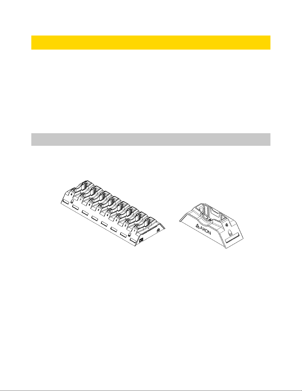
Axon Body 3 cameras capture video and audio recordings. Users place their cameras in an
Axon Body 3 Dock to securely upload the content securely to your agency’s Axon
Evidence.com instance.
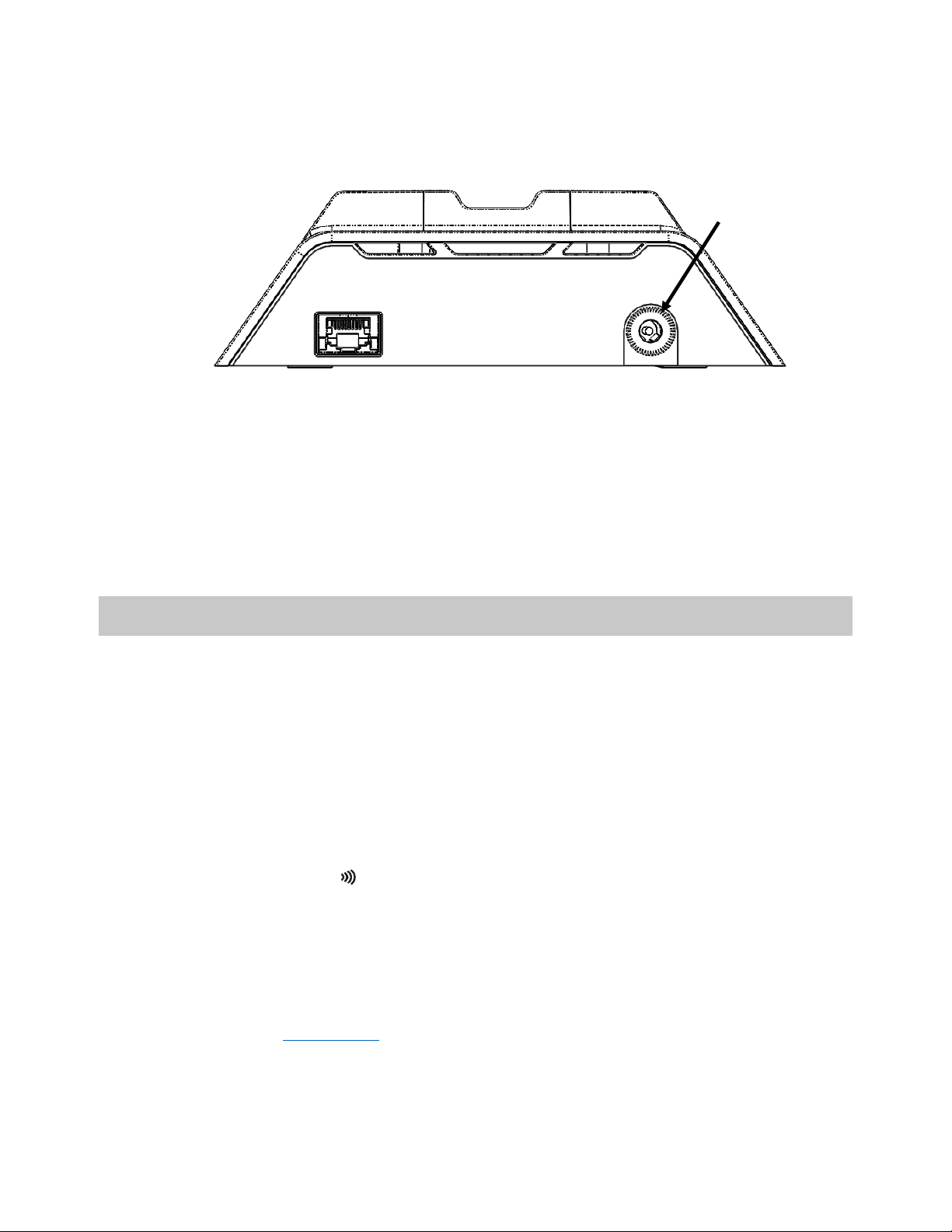
The Axon Body 3 camera is true mobile device and when docked each camera must obtain
its own IP address to establish a direct encrypted communication channel to your agency’s
Axon Evidence.com instance. The Axon Body 3 Dock only functions as an Ethernet adapter,
an unmanaged network switch, and charger for Axon Body 3 cameras.
Axon Body 3 Cameras and Network Infrastructure
The network requirements for Axon Body 3 cameras are provided below:
Note: If you are moving from previous generation Axon body-worn cameras to Axon Body 3
cameras, you may be required to make changes to your network infrastructure. If your
agency has concerns or questions about any of the network considerations, please contact
your Axon representative in advance of your deployment so that they can address these
issues as early as possible.
•In response to the availability of high-speed Internet connectivity the Axon Body 3
camera has increased upload speeds. Network administrators should anticipate 20
to 25 Mbit/s per device if not regulated.
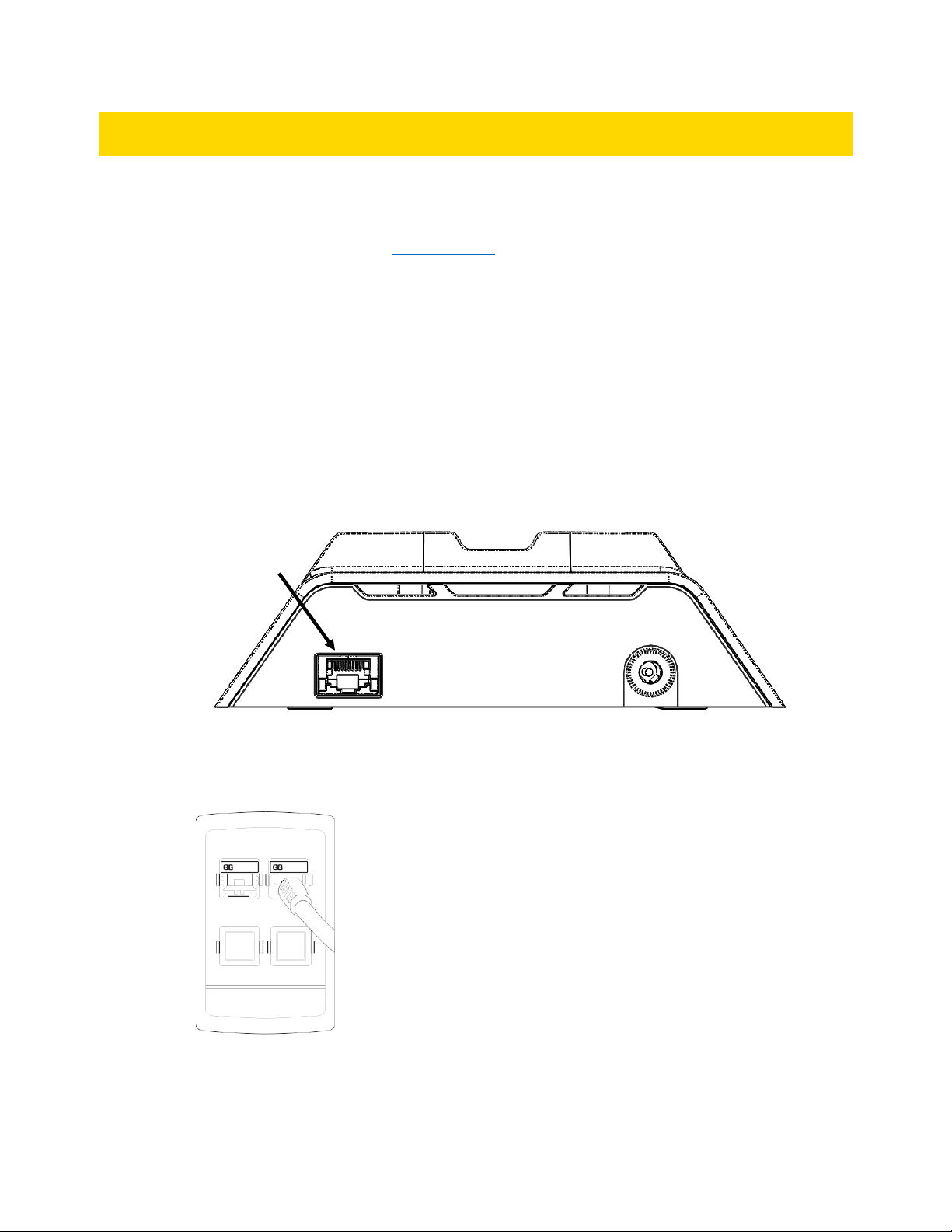
•Each Axon Body 3 camera requires its own IP address when docked. The Axon Body
3 Dock itself has no IP address, but each bay has its own Media Access Control (MAC)
address. The list of MAC address for each bay is shown on the end of each dock.
•Static IP addresses are not supported, as the Axon Body 3 camera is a true mobile
device that can be docked anywhere.
oDynamic Host Configuration Protocol (DHCP) should be used to provision the
IP address and network settings. Each Axon Body 3 Dock bay functions as an
ethernet card, with its own MAC address.
oIf your agency currently uses static IP addresses for older Axon Docks and
other equipment, and you want to continue to use specific IP addresses for
devices in specific dock bays, DHCP reservations can be used. Because each
Axon Body 3 Dock bay has its own MAC address, these addresses can be
used for DHCP reservations. The list of MAC address for each bay is shown
on the end of each dock.

Axon Body 3 Dock Installation Manual
Axon Enterprise, Inc. Page 8 of 25
•Upload bandwidth restrictions cannot be set for an Axon Body 3 Dock. If your agency
requires upload rate-limiting, there are two options available:
o(Recommended) Deploy rate-limiting restrictions in your layer-3 networking
infrastructure as needed.
This is the best option. Your network switches have an aggregated view of
devices and traffic, and can allocate all available bandwidth to a single device
or small number of devices when they are the only ones with uploads
queued, while limiting the total bandwidth when large numbers of devices
are uploading at once.
o(Not recommended) There is an agency-wide Axon Body 3 camera setting in
Axon Evidence.com that can limit the upload rate of all cameras when
docked. While this can be done, it is not optimal, since all Axon Body 3
cameras will honor this restriction even when there are few or no other
devices uploading.
•Axon Body 3 cameras require direct access to Axon Evidence.com through an Axon
Body 3 Dock and do not support using a proxy server.
Network Requirements
The Axon Dock and cameras are network connected devices and should be installed only on
networks trusted by the agency in accordance with agency policy. DO NOT expose the Axon
Dock and cameras directly on the Internet. The Axon Dock and cameras must be connected
behind a firewall or secure network to prevent unauthorized connections being initiated
from the Internet or from clients not trusted by the agency.
To get the dock up and running, you may need some assistance from your IT department.
Firewall Configuration
The dock and Axon devices do not require any incoming data ports for regular operation. For
proper operation, Axon Body 3 cameras require the following out- bound firewall ports:
•Port 443 (TCP) opened for outgoing traffic to your agency’s Axon Evidence.com
instance. This is used to send video and data files to Axon Evidence.com using the
HTTPS protocol.
•Port 80 for time synchronization.

Axon Body 3 Dock Installation Manual
Axon Enterprise, Inc. Page 9 of 25
Axon Body 3 Dock Installation
Install your Axon Dock as described in the following procedure.
Before installing an 8-Bay Dock, Axon recommends you determine if the dock will be
mounted on a desktop or on a wall mounting. 1-Bay Docks can be placed on a desktop or
shelf as needed.
If you do not have an Axon Evidence.com account, Axon recommends that you contact your
Axon administrator and ask for an account invitation. When the email invitation arrives,
accept the invitation and create an account. This email invitation will come from
noreply@evidence.com.
1. Remove the dock from the box and confirm that all pieces are present.
2. Plug the Ethernet cable into the WAN port.
3. Plug the other end of this Ethernet cable into an active Internet port, which connects to
your agency network.
4. Connect the two segments of the power cord included with the dock.
WAN port

Axon Body 3 Dock Installation Manual
Axon Enterprise, Inc. Page 10 of 25
5. Plug the power cord into the dock.
6. Connect the other end of the power cord to a standard power outlet.
For 8-Bay Docks, the green power LED on top of the dock will light up when the dock is
powered. For 1-Bay Docks, check for power by placing an Axon Body 3 camera in the
dock and looking for the charging icon on the camera display.
Once a dock is installed, it can be used to register and charge Axon Body 3 cameras.
Dock Registration
Registration and configuration of Axon Body 3 Docks is not required, but registering does
make inventory management of your docks, including returns through Axon Evidence, much
easier. Your dock must be registered to use the Device Profile page in Axon Evidence.com.
Axon recommends the following best practices:
•Use Axon Device Manager (ADM) to register and name Axon Body 3 Docks for
inventory and management purposes.
When using the ADM Tap Device option to look for the NFC tag, hold your mobile
device near the icon on the dock. For the 1-Bay dock, the icon is on the side of the
dock nearest to the Ethernet port. For the 8-Bay dock, the icon is near bay 1, on the
side of the dock near the power connection.
•Use logical names when changing the Device Name in Axon Evidence.com. That will
assist in understanding the location and purpose for the Axon Body 3 Docks.
•Use the Device Home feature in Axon Evidence.com if you have more than one
location with Axon Body 3 Docks.
Power
connection

Axon Body 3 Dock Installation Manual
Axon Enterprise, Inc. Page 11 of 25
Wall Mounting an Axon Dock
This section provides information on using a wall mount for the 8-Bay Axon Body 3 Dock.
Axon Body 3 Docks should be installed in an area with redundant power, redundant HVAC,
and with an ambient temperature between 41 °F to 95 °F (5 °C to 35 °C).
Note: The wall mount for the 8-Bay Axon Body 3 Dock is the same as the mount used for
Axon Body 2 and Axon Flex 2 6-Bay Docks. If you already have this wall mount, you can reuse
it with the 8-Bay Axon Body 3 Dock by removing the core and 6-Bay Dock modules and
attaching the 8-Bay Axon Body 3 Dock.
Safety Instructions
Before mounting your Axon Dock:
•Ensure that the area behind the wall where the dock will be located is clear of
obstructions to avoid damage to surroundings, pipes, or existing wiring.
•Ensure that your cables meet all applicable building and fire codes. For in-wall
installation, most require UL-rated wire labeled CL2 or CL3.
•Leave adequate space around all sides of the Dock for proper ventilation and
maneuvering around it without people or items bumping it
Tools and Materials
Tools
Materials
•Cable-wire tester/locator •Wall Mount Kit
•Level
•Pencil
•Power drill and bits
•Screwdriver
•Stud finder
•Tape measure

Axon Body 3 Dock Installation Manual
Axon Enterprise, Inc. Page 12 of 25
Dimensions
The dimensions below show the mounting hole locations of the Wall Mount Bracket and the
overall size of the assembly with the dock attached. The power supply is designed to go
behind the unit on the horizontal shelf.
Note: Dimensions are shown in inches and centimeters.
You can use the overall size of the wall mount bracket to determine the spacing and fit
between multiple assemblies. The Ethernet and Power connections are also shown above.
Installation
Step 1: Preparation
1. Ensure that you have all necessary hardware and cables required to complete the
installation.
2. Read all the manufacturer’s installation instructions for both the dock and the Wall
Mount Bracket.
3. Decide if you will leave the cables showing or hide them in the wall behind your dock.
Step 2: Attach the Dock to the Wall Mount Bracket
1. Place your dock on the Wall Mount Bracket.
2. Align the holes of the dock with the holes on the bracket.
14.000 in CTR TO CTR
[35.6 cm]
17.50 in
[44.5 cm]
5.21 in
[13.2 cm]
7.375 in
CTR TO CTR
[18.7 cm]
7.55 in
[19.2 cm]
8.51 in
[21.6 cm]
Ethernet
Power

Axon Body 3 Dock Installation Manual
Axon Enterprise, Inc. Page 13 of 25
3. Use the screws provided in the dock wall mount kit to attach the dock to the bracket.
4. As the screws come out the back of the bracket, attach the washers and add the wing
nuts.
5. Finish tightening all the screws.
Step 3: Identify Dock Placement
Determine the best wall location for mounting the dock.
1. Look for a location away from heat sources and direct sunlight that does not obstruct
movement.
2. Choose a location close to an electrical outlet and a network outlet. Measure the length
of the dock’s power cord to be sure that it will reach.
Step 4: Attach the Wall Mount Bracket to the Wall (Stud mount)
Your Wall Mount Kit comes with hardware for mounting the bracket to a stud or mounting
directly into drywall. If you are going to install the bracket to drywall, go to Step 5: Attach the
Wall Mount Bracket to the Wall (Drywall Mount).
Note: Use the longer screw for mounting the bracket into a stud.
1. Using a stud finder, mark the location of each stud’s center with a pencil.
2. Use a nail to confirm a stud has been located.
Note: Depending on the wall construction, you may not be able to mount both ends of
the Wall Mount Bracket into the stud.
3. Use the drywall anchors in the Wall Mount Kit for the other mounting locations if
needed.
4. Position the Wall Mount Bracket on the wall and align the mounting keyhole in the left
side of the bracket with the center line of the stud.
5. Use a level to ensure the bracket is level before marking the holes.
6. Mark the center of the left side keyholes in the center of each wall stud.
7. Using a power drill, drill a pilot hole smaller than the screw diameter.

Axon Body 3 Dock Installation Manual
Axon Enterprise, Inc. Page 14 of 25
8. Install the screws into the stud until there is 1/8” (3.2 mm) of space between the bottom
of the screw head and the wall.
This will allow the bracket to be placed onto the screws and settle in the keyhole (the
holes in the bracket are shaped like keyholes to make it easier to adjust the mount’s
position on the wall).
9. Repeat steps 5–8 for the other side of the mount bracket.
10. After the Wall Mount Bracket is positioned correctly, tighten all of the screws.
11. Go to Step 6: Connect the Cables.
Step 5: Attach the Wall Mount Bracket to the Wall (Drywall Mount)
Your Wall Mount Kit comes with hardware for mounting the bracket to a stud or mounting
directly into the drywall. If you are installing the bracket to a wall stud, go to Step 4: Attach the
Wall Mount Bracket to the Wall (Stud mount).
Note: Use the screw-in anchors and shorter screws for drywall installation.
1. Find the location where you want to mount the Wall Mount Bracket.
2. Locate the Wall Mount Bracket on the wall.
3. Use a level to ensure the bracket is level before marking the holes.
Mark the center of the four keyholes on the wall.
4. Remove the Wall Mount Bracket and screw in the drywall anchors in each location.
5. Screw in each of the screws until there is 1/8” (3.2 mm) of space between the bottom of
the screw head and the wall.
6. This will allow the bracket to be placed onto the screws and settle in the keyhole.
Step 6: Connect the Cables
1. There is space provided on the horizontal shelf to secure the power supply for the dock.
2. Position the power supply between the slots in the bracket and secure the power supply
to the bracket with the Velcro strap.
3. Route the barrel connector around the edge guard and plug the barrel connector into
the power jack on the dock.

Axon Body 3 Dock Installation Manual
Axon Enterprise, Inc. Page 15 of 25
4. You can secure the cable in position with the attached zip tie and the associated slots in
the bracket.
5. Plug the power supply cable into a power strip or nearby AC outlet.
6. Plug the CAT 5e (or better) cable from your agency’s network data jack into the WAN port
on the dock.
You can secure the cable in position with the attached zip tie and the associated slots in
the bracket.

Axon Body 3 Dock Installation Manual
Axon Enterprise, Inc. Page 16 of 25
Troubleshooting and Other Information
The Axon Body 3 Dock provides a wired network connection for Axon Body 3 cameras. The
Axon Body 3 Dock only functions as an Ethernet adapter, an unmanaged network switch,
and charger. As long as an Axon Body 3 Dock has power and a network connection, it should
function correctly.
Go to help.axon.com and refer to the Axon Body 3 section to check for any additional
troubleshooting information for the Axon Body 3 Dock.
Technical Support
Visit www.axon.com and view the Support options or call 1-800-978-2737.
Warranty Policy
Axon Enterprise warranty provisions are applicable on all Axon Body 3 system products. See
Axon Enterprise’s website, www.axon.com, for detailed warranty information.

Axon Body 3 Dock Installation Manual
Axon Enterprise, Inc. Page 17 of 25
Warnings
This document presents important safety warnings, instructions, and information intended
to minimize hazards associated with the use of Axon Enterprise, Inc.’s (Axon)camera
systems. These instructions and warnings are for your protection as well as the safety of
others. Read the entire document before using any Axon system.
These warnings and instructions are effective July 31, 2019 and supersede all prior revisions.
The most current warnings are also available online atwww.axon.com.
1. Read and obey. Read, understand, and follow all current Axon system instructions,
manuals, warnings, and relevant Axon training materials before using any Axon system.
Failure to do so could increase the risk of serious injury, system malfunctions, or loss of
data.
2. Obey applicable laws, regulations, and agency guidance. Use the Axon systems only
in accordance with applicable federal, state, and local laws and other regulations or legal
requirements.
This document uses a signal word panel to mark specific warnings:
WARNING
This signal word panel indicates a potentially hazardous situation which if not avoided could result
in fire, electric shock, damage, system malfunctions, death, or personal injury.
CAUTION
This signal word panel indicates a potentially hazardous situation which if not avoided or heeded
could result in minor or moderate injury.
Warnings may be followed by instructions and information to help avoid the hazard and
improve safety.
WARNING! POTENTIALLY EXPLOSIVE ENVIRONMENTS
Failure to follow these safety instructions could result in fire, electric shock, damage, system
malfunctions, death, or personal injury.
Potentially explosive environments. Electric energy in a potentially explosive area could cause an
explosion or fire, resulting in serious injury or even death. Areas with a potentially explosive
atmosphere are often, but not always, marked clearly. Potential areas may include: fueling areas
(such as gas stations); below deck on boats; fuel or chemical transfer or storage facilities; vehicles
using liquefied petroleum gas (such as propane or butane); areas where the air contains chemicals
or particles (such as grain, dust, or metal powders); and any other area where you would normally
be advised to turn off your vehicle engine. Axon Flex, Axon Flex 2, Axon Body, Axon Body 2, Axon
Body 3, Axon Fleet, and Axon Fleet 2 cameras contain wireless transmission technology that
transfers radio frequencies over the air as a form of energy transfer. Wireless transmission has been

Axon Body 3 Dock Installation Manual
Axon Enterprise, Inc. Page 18 of 25
WARNING! POTENTIALLY EXPLOSIVE ENVIRONMENTS
deemed a risk factor in igniting an explosive environment. In situations where the Axon camera
operator needs to enter a potentially explosive environment, Axon recommends that the user err on
the side of caution and power off the camera before entering the explosive environment. An Axon
camera should be treated the same as a cellular telephone would be treated in this situation.
WARNING! NEODYMIUM RARE EARTH MAGNETS
Failure to follow these safety instructions could result in fire, electric shock, damage, system
malfunctions, death, or personal injury.
Neodymium Magnets. The Axon magnet mount contains a neodymium magnet which emits strong
magnetic fields that can affect a pacemaker, ICD (implantable defibrillator), VNS (vagal nerve
stimulator), and other implanted electrical medical devices. Many of these devices are made with a
feature that deactivates it when in contact with a strong magnetic field. Therefore, care must be
taken to avoid inadvertently deactivating such devices when in close proximity to the Axon magnet
mount. Persons with a pacemaker, ICD, VNS, or other implanted electrical medical device
should not wear the Axon magnet mount.
WARNING! AXON DOCK AND TASER 7 DOCK USE
Failure to follow these safety instructions could result in fire, electric shock, damage, system
malfunctions, death, or personal injury.
Electrical Warnings. To reduce the risk of fire, electric shock, or injury to persons when using any
Dock, follow basic precautions, including the following:
•Plug into a grounded 3-prong outlet and do not remove the ground prong.
•Verify the outlet is installed according to applicable local electrical codes.
•Do not use an adapter or an extension cord.
•Disconnect power and verify power disconnect before servicing.
•Keep away water, other liquids, corrosive substances, and flammable materials and vapors, such
as gasoline. Keep away from sources of static electricity. Static electricity can cause damage to
the Dock or cause it to malfunction.
•In the event of electrostatic discharge or intermittent power fluctuation, power will need to be
cycled to the unit to regain full functionality.
CAUTION! AXON DOCK USE
Maintenance. Failure to properly maintain the Dock may cause the system to malfunction or not
operate optimally.
To reduce the risk of malfunction, including failure or loss of data:
1. Anchoring and Installation. Docks should be securely placed on a flat surface; when
anchoring (for example, to the wall or other hard and stable surface) be sure to use
appropriate hardware. The following are guidelines for installation:
•Comply with your local and other applicable building and electricity regulations and
codes;

Axon Body 3 Dock Installation Manual
Axon Enterprise, Inc. Page 19 of 25
•Install in an area with redundant power and redundant HVAC;
•Install in an area with an ambient temperature between 41 °F to 95 °F (5 °C to 35 °C);
•Leave adequate space around all sides of the Dock for proper ventilation and
maneuvering around it without people or items bumping it;
•Do not expose cords or wires which can be a tripping hazard; and
•If mounted to a wall, secure to wall studs or with drywall or concrete anchors, as
applicable.
2. Indoor use only. The Dock is manufactured for indoor use only. Install the Dock indoors,
away from excessive moisture, liquids, corrosive substances, or heat, dust, direct
sunlight, water, or other negative environmental factors. In-car installations may expose
the Dock to excessive heat.
3. Avoid water, other liquids, and wet locations. Do not install the Dock near or around
liquids, water, or water pipes. Do not get the Dock wet.
WARNING! AXON SYSTEM USE
Failure to follow these safety instructions could result in fire, electric shock, damage, system
malfunctions, death, or personal injury.
To prevent potential injuries or system malfunctions or compromise, take the following
precautions:
1. Handling the components. Ensure proper connections between the Axon components
(e.g., the Axon Body camera is correctly inserted into the Dock). Do not drop, crush,
disassemble, deform, open, incinerate, or insert foreign objects into the Axon system
components.
2. Operate safely. Be careful and attentive while using an Axon system, including while
operating a vehicle, riding a bicycle, operating other conveyance, when dealing with
potentially violent individuals, or handling a hazardous or potentially hazardous
situation. If you use an Axon system while operating a conveyance, keep in mind the
following guidelines:
•Do not take notes, look up information, adjust the camera, or perform any other
activities that require or distract your attention. Give full attention to driving or riding
and to the road. Using a mobile device or mobile data terminal (MDT) while driving
or riding may be distracting.
•Get to know the Axon system and its features.

Axon Body 3 Dock Installation Manual
Axon Enterprise, Inc. Page 20 of 25
•Position the Axon system’s camera and activation buttons within easy reach.
3. Navigate safely. If your Axon system is paired or combined with a mobile phone or
device or MDT and has applications that provide maps, digital compass headings,
directions or location-based tracking or navigation assistance, these applications should
only be used for basic navigation assistance and should not be relied on to determine
precise locations, proximity, distance, or direction. Maps, digital compass, directions, and
location-based applications provided by Axon depend on data collected and services
provided by third parties. These data services are subject to change, may not be
available in all geographic areas, or may not be accurate, resulting in maps, digital
compass headings, directions, or location-based information that may be unavailable,
inaccurate, or incomplete. Compare the information provided on the Axon system to
your surroundings and defer to posted signs to resolve any discrepancies.
4. Wire and mount safety. If the system causes bodily discomfort discontinue use or find
an alternative way to wear the equipment. Never wrap wires around your neck.
5. Avoiding hearing damage. Hearing damage, impairment, or loss may occur and may be
permanent if an Axon Flex or Axon Flex 2 camera is mounted near your head and used
at high volume. Set the volume to a safe and comfortable level. Be advised that you can
adapt over time to a higher volume of sound that may sound normal but can be
damaging to your hearing.
6. Choking hazards. The Axon systems contain small parts, which may present a choking
hazard. Keep the Axon systems and their accessories away from small children.
7. Repetitive motion. When you perform repetitive activities such as typing on a mobile
phone or device, you may experience occasional discomfort, which may create injury,
including permanent injury, in your hand, wrist, arm, shoulder, neck, or other part of
your body. Take frequent breaks and if you have discomfort during or after use, stop use
and see a physician.
8. Use only Axon-approved components, batteries, and accessories. Only Axon-
approved components, batteries, and accessories are to be used with the systems. Use
of anything other than Axon-approved components, batteries, or accessories will void
the warranty, may cause malfunction, and may put the user or other person at risk of
injury.
WARNING! BATTERIES
Failure to follow these safety instructions could result in fire, electric shock, damage, system
malfunctions, death, or personal injury.
Damage to or improper handling of batteries could result in fire, electric shock, damage, system
malfunctions, loss of data, or personal injury.
This manual suits for next models
1
Table of contents
Other Axon Docking Station manuals