Grizzl-E Ivy Home User manual

Ivy Home™
Smart EV
Charger
User Manual and
Installation Guide
Powered By
Grizzl-E™

2
Ivy Home™Smart EV Charger
User manual and installation guide.
Manual revision: 1.0
Black
GRS-14-24-P
Model Numbers:
White
GRS-14-24-AB
Ivy Home™ is a trademark of Ontario Charging Network LP, 2022.

3
Ivy Home Smart EV Charger
The Ivy Home Smart EV Charger is a sleek and stylish Level 2 EV Wi-Fi connected charger
powered by Grizzl-E™. It is made in Ontario and designed to withstand the harshest
Canadian weather conditions.
Ivy Home comes with a 24 output cable and 24in NEMA 14-50 input cable. Internal design
and components of the charger have been selected to maximize the operational life of the
device.
The charger provides your electric vehicle with up to 10kW of power. Maximum current output
can be set through DIP Switches to provide 16 Amps (A), 24A, 32A or 40A adjustable maximum
current.
Important safety instructions
This document contains instructions and warnings that must be followed when installing
and using The Ivy Home Smart Electric Vehicle Supply Equipment (EVSE). Before installing or
using the EVSE, please read this document carefully including any WARNING and CAUTION
symbols.
Warning: risk of personal injury
Warning: risk of electric shock
Warning: risk of re
Caution: risk of damage to equipment
• This guide provides instructions for the home charger and should not be used for any
other product. Before installation or use of this product, please review this manual
carefully and consult with a licensed electrical contractor to ensure compliance with
local building codes and safety standards.
• Ensure that the materials and the installation procedures follow local building codes and
safety standards.
Symbol legend:

4
Repair and maintenance clause
• Even though this product does not require routine maintenance, periodic inspections are
recommended to ensure that all parts remain and good working order and there is no
damage.
• Do not aempt to disassemble, repair, tamper with, or modify any components of the
product.
• Read all the instructions before using this product.
• Children should not use this device. Keep out of reach of children.
• Do not put ngers into the EV connector.
• Do not touch live electrical parts.
• Do not use this product if the exible power cord or EV cable is ragged, has broken
insulation, or shows any other signs of damage.
• Do not use this product if the enclosure or the EV connector is broken, cracked, open,
or shows any other indication of damage.
• Improper connection of the equipment grounding conductor can result in a risk of
electric shock. Please check with a licensed electrician if you are in doubt as to whether
the product is properly connected and grounded.
Basic precautions should always be followed when using electrical products, including the
following:
WARNING: This equipment is intended only for charging vehicles
that do not require ventilation during charging. Please refer to your
vehicle owner’s manual to determine ventilation requirements.

5
Product features
The Ivy Home Smart EV Charger
• J1772 AC Level 2 (208-240 VAC), 40A Continuous Rated (9.6 kW).
• Adjustable maximum current output (40A, 32A, 24A, 16A) to support multiple circuit
ratings (50A, 40A, 30A, 20A).
• Extreme duty, rigid & compact design.
• Heavy-duty aluminum cast enclosure; water resistant enclosure for indoor or outdoor use
• Wi-Fi connectivity and smart charging features.
• EasyEVplug™ holster or with cable management system.
• Plug-in conguration for easy portability.
• Wallmount with security features, including single stud mount, pedestal, bollard/pole
single and dual port.
• Ul certied.
• Energy star certied.
Wi-FI connectivity
Adjustable maximum current output to support multiple circuit ratings
The Ivy Home EV Charger features the ability to adjust the maximum charger current output
to allow the use of a 50A, 40A, 30A, or 20A dedicated circuit as follows:
50A circuit rating: max 40A (9.6kW) output
40A circuit rating: max 32A (7.68kW) output
30A circuit rating: max 24A (5.76kW) output
20A circuit rating: max 16A (3.84kW) output
The default factory seing is 40A (9.6kW). To change the maximum current output, refer to
Chapter 3.1 Adjust maximum current output on page 11. If you are unsure of the circuit
ratings in your home, consult a licensed electrical contractor.
The Ivy Home Smart EV Charger connects to Wi-Fi networks through the use of an ESP32
controller. Ivy Home is compatible with all OCPP 1.6 commands.
For more information on how to connect Ivy Home to a Wi-Fi network, see Chapter 8. Set up
smart functionality on page 23.

6
Product specications
Description Specications
Model Numbers
EVSE Level
Max Output
Rating
Alternate
Adjustable
Output Ratings
Charge Cable Length
Electrical
Circuit/Input Power
Requirements
Input Power
Connection
Installation Rating
Operational
Ratings
GRS-14-24-P GRS-14-24-AB
SAE J1772; AC Level 2
40A; 9.6 kW Maximum Output – For use with 50A Circuit Rating
32A; 7.68 kW Maximum Output – For use with 40A Circuit Rating
24A; 5.76 kW Maximum Output – For use with 30A Circuit Rating
16A; 3.84 kW Maximum Output – For use with 20A Circuit Rating
24 .
Circuit Requirement: Dedicated Single Phase 208-240VAC,
50/60 Hz.; Branch Breaker: Double pole;
Circuit Conductors: Line 1, Line 2, Earth / Ground
Standard Plug-in: NEMA 14-50 Receptacle.
Plug is removable for Hardwire Connection.
NEMA 4X, Indoor/Outdoor Rated
Temperature: -22⁰F to 122⁰F (-30⁰C to 50⁰C);
Humidity: 95% RH non-condensing
Mounting Wall or Pedestal Installation
Overall Dimensions
Display & Indicators
EVSE: 10.25 x 6.25 x 3.75 inches (26.0 x 16.0 x 9.3 cm)
LED Charge Status Indicators (Power/Ready, Charging, Fault)
Cable Management
Standards &
Compliance
EasyEvPlug™with cable management
UL Certied, Energy Star Certied
21lbs (9.5kg)
Overall Weight

7
Table of Contents
1. Introduction & unpacking ................................................................................................... 8
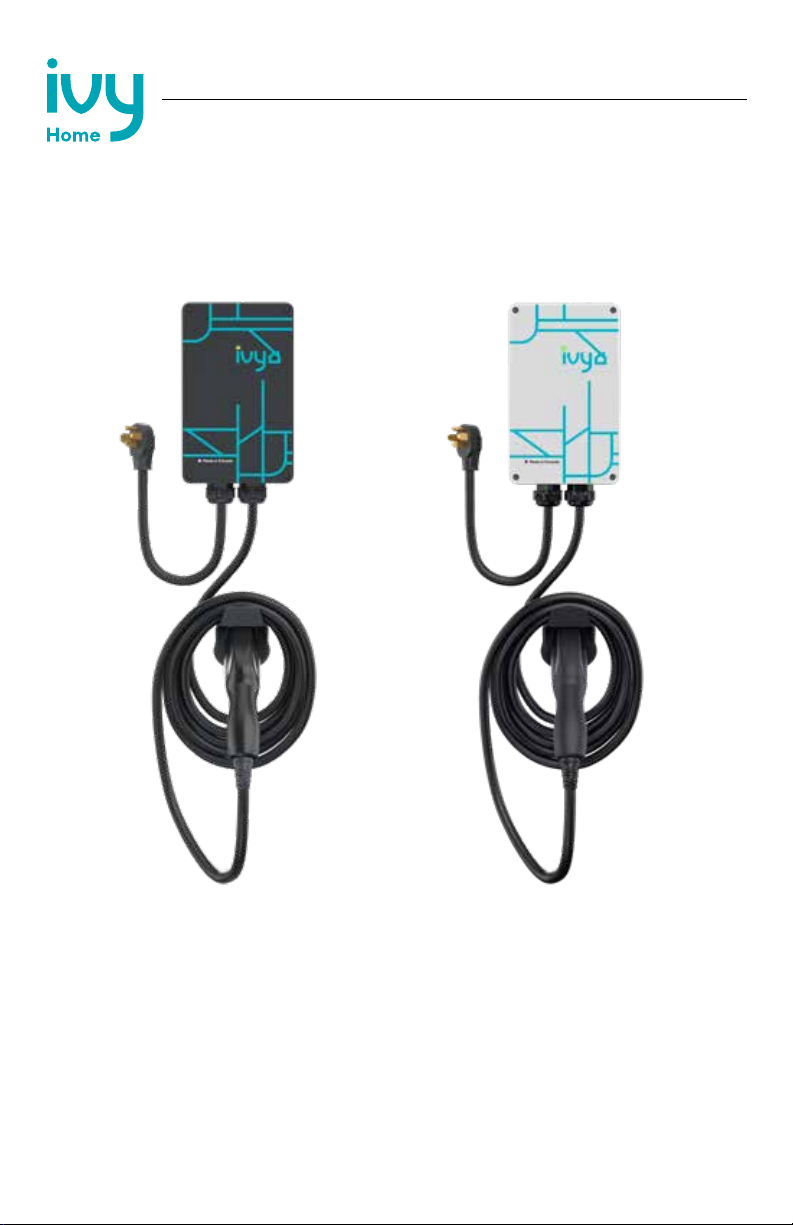
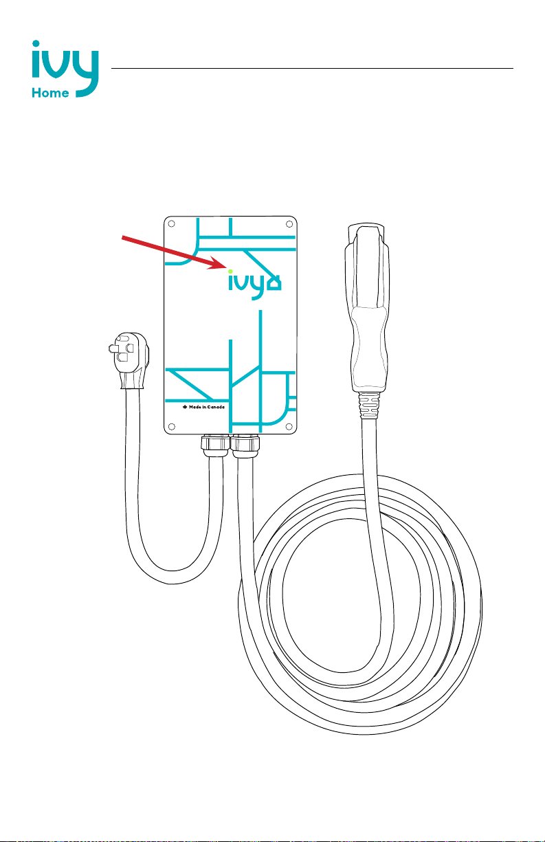
1.1 Your charger ...........................................................................................................................8
1.2 Package contents ................................................................................................................9
2. Installation planning and service wiring...........................................................................10
2.1 Electrical source requirements ........................................................................................10
2.2 Grounding instructions ....................................................................................................10
3. Adjustable maximum current output.................................................................................11
3.1 Adjust maximum current output.......................................................................................11
4. Installation .........................................................................................................................14
4.1 Tools & parts required for installation ...........................................................................14
4.2 Install the charging station .............................................................................................15
5. Input wiring connection (optional hardwire connection).................................................18
6. EasyEvPlug holster and cable management system....................................................... 20
7. Charging status indicators and buzzers ..........................................................................21
7.1 Charging status indicators ...............................................................................................21
7.2 Fault indicators ..................................................................................................................22
7.3 Reset charger......................................................................................................................22
8. Set up smart functionality................................................................................................ 23
8.1 Network requirements.......................................................................................................23
8.2 Connect the charger to Wi-Fi ........................................................................................23
8.3 Wi-Fi connection indicator..............................................................................................24
8.4 Troubleshoot connection errors....................................................................................25
9. Disconnect from Wi-Fi....................................................................................................... 26
9.1 Reset Wi-Fi............................................................................................................................26
10. Operation ........................................................................................................................ 27
10.1 Connect and charge .......................................................................................................27
10.2 Smart charging ................................................................................................................27
10.3 Stop charging ..................................................................................................................27
11. General product care and use information .................................................................... 28

8
1. Introduction & unpacking
NEMA 14-50
Plug
Output Cable
J1772 Connector
Input Cable
Indicator Light
1.1 Your charger

9
Mounting Bracket (x1)
Security Pin (x1)
Phillips-head
Screws (x4)
Holster (x1)
Robertson Head
Screws (x2)
Socket Cap
Screw (x4)
Anchor (x4)
1.2 Package contents
Mounting Kit
EasyEvPlug Holster

10
WARNING: Disconnect the power supply before installing, adjusting,
or repairing the charger. Failure to do so may result in physical injury
or damage to the power supply system and the charger.
2. Installation planning and service wiring
• Prior to mounting, locate an available electrical source that can support the following
input requirements for the charger per local Electrical Safety Code requirements:
»40A maximum output seing (default factory seing): a DEDICATED CIRCUIT rated
for 50A; 208-240 VAC, 50-60 Hz, Single Phase must be used.
»32A maximum output seing (optional seing): a DEDICATED CIRCUIT rated for 40A;
208-240 VAC, 50-60 Hz, Single Phase must be used.
»24A maximum output seing (optional seing): a DEDICATED CIRCUIT rated for 30A;
208-240 VAC, 50-60 Hz, Single Phase must be used.
»16A maximum output seing (optional seing): a DEDICATED CIRCUIT rated for 20A;
208-240 VAC, 50-60 Hz, Single Phase must be used.
• A Double Pole Circuit Breaker of the circuit rating must be used.
• The charger has built-in GFCI protection. Additional GFCI protection upstream of the
charger is not necessary. In locations where GFCI at the outlet is mandated by code, the
charger will not experience negative eects.
• The charger can connect to a Standard NEMA 14-50 receptacle, or the unit can be
hardwired.
2.2 Grounding instructions
The charger must implement equipment grounding through a permanent wiring system or
an equipment grounding conductor. Use a cable with a dedicated grounding conductor
connected to the equipment ground terminal block.
CAUTION: To reduce the risk of re, connect only to a circuit provided
with the minimum branch circuit overcurrent protection requirements
in accordance with the National Electrical Code ANSI/NFPA 7- and
the Canadian Electrical Safety Code, Part 1, C22.1. If you are unsure if
the circuit meets these requirements, consult a licensed electrician.
2.1 Electrical source requirements

11
3. Adjustable maximum current output
The Ivy Home Smart EV Charger features the ability to adjust the maximum charging station
current output to support 50A, 40A, 30A, or 20A dedicated circuit ratings as follows:
Circuit Rating Maximum Charging Station Output
50A 40A (9.6 kW)
40A 32A (7.68 kW)
30A 24A (5.76 kW)
20A 16A (3.84 kW)
• The charger default factory maximum current output seing is 40A (9.6 kW) for use with a
50A Circuit Rating.
• The circuit must be a DEDICATED CIRCUIT 208-240 VAC, 50-60 Hz, Single Phase.
• Requirements govern that only 80% of the circuit rated load may be utilized, hence the
higher Circuit Ratings Requirement relative to maximum charging station output.
To adjust the maximum current output seing:
1. Remove the front cover by removing the 4 screws at each corner of the charging station.
Use a 5/32” (M4) Allen key to remove the screws.
3.1 Adjust maximum current output

12
2. With the front cover placed to the side, locate the DIP switch on the charging station
circuit board. The DIP switch is a 4-position switch on the main circuit board, located
directly to the le of the LED.
UP DOWN
WARNING: Do not touch live electrical parts. Disconnect the power
supply to the charging station before adjusting the DIP switches.
Failure to do so may result in physical injury or damage to the power
supply system and the charging station.
UP UP
CAUTION: The LED pipe is aached to the front cover. When the
front cover is removed, place it on a at surface facedown to avoid
damage to the LED pipe.

13
40A Maximum Current Output
(Factory Default Setting)
32A Maximum Current Output
24A Maximum Current Output
16A Maximum Current Output
UP DOWN
UP UP
UP DOWN DOWN
DOWN DOWN
DOWN DOWN DOWN
UP
UP UP
UP
Switch 1 Switch 2 Switch 3 Switch 4
Maximum Current Output DIP Switch Setting
3. Adjust the maximum current output to either 40A, 32A, 24A or 16A, using the following
combination of DIP switch seings:
4. Once the DIP switch seing is adjusted, reassemble the charging station. Reinstall the top
cover to the charging station using the following torque force to secure the 4 socket cap
screws:
Screw Torque
13.88 lbf-in (1.56Nm)5/32”

14
4.1 Tools & parts required for installation
Tool Size Source of Supply Remark
Mounting bracket
Robertson-head
screw (x2)
Phillips-Head
screw (x4)
Anchors
(x4)
EasyEVPlug™
Holster
Socket cap screw
(x4)
Allen key
Philips screwdriver
10”x5.75”x1.25”
(255x148x3`1 mm)
#14
#8
#8
5”x3.5”3.5”
(127x89x89 mm)
3/16”
(M5)
PH3
5/32”
(M4)
Included with product
Commercially available
For mounting the charger to
the wall/structure
For installing the mounting
bracket to the wall/structure
For installing the
EasyEVPlug™to the wall/
structure
For installing the
EasyEVPlug™to the
wall/structure
To store the EV charging
plug and cable
For securing the charger to
the mounting bracket
For charging station cover
screws
For holder installation and
optional hardwire install
Allen key 3/16”
(M5)
Commercially available For installing the enclosure
plate to the back of the
station body
4. Installation
Prior to mounting, determine the location of an acceptable mounting support. All charging
station products must be anchored into a mounting support such as a 2” x 4” stud or a solid
concrete wall. DO NOT mount this unit directly to a stucco/drywall/wall board.

15
4.2 Install the charging station
1. Separate the front and back piece of the mounting bracket by pushing down on the
notch.
2. Aach the front piece of the mounting bracket to the back of the charging station
using the socket cap screws. Ensure the top of the mounting bracket is matched with
the top of the charging station.
Back Piece
Front Piece
TOP

16
The back piece of the mounting bracket has 3 holes to support aachment to various
surfaces. Use the top two holes to aach the mounting bracket to a wall stud.
Mounting screw recommendations:
• For nished walls supported by wood studs, use #14 or M6 tapping screws (included).
• For masonry walls, use M6 mechanical screws (commercially available).
• Use following torque force:
Screw Torque
M6
1/4”
43.4 lbf-in
43.4 lbf-in
3. Secure the back piece of the mounting bracket to the wall or other suitable structure
using the Robertson-head screws.
The NEMA 14-50 cable is approximately 24” (30cm) long. Mount the unit so the NEMA 14-50
cable is straight but can be plugged into the outlet without stretching. The NEMA outlet
should be located no less than 20~26” (50-60cm) from the ground or as dened by applicable,
local electrical safety codes and standards.
44.85Nm
44.85Nm

17
4. Mount the charger on the wall by securing the front piece of the mounting bracket to the
back piece of the mounting bracket.
5. Secure the charger in place by inserting either the security pin or the outdoor security
lock into the mounting bracket.
6. Plug in the power cord to the NEMA 14-50 wall outlet/receptacle. Ensure the indicator
light alternates between Blue and Magenta, indicating the charger is ready and not
connected to Wi-Fi.

18
5. Input wiring connection (optional hardwire connection)
1. Choose the appropriate conduit in accordance with all applicable, local, and electrical
safety codes and standards.
2. Using the appropriate tool, clamp the ring wire terminal to the copper wire. For non-
insulated terminals, use the heat shrink tube to cover the non-insulated portion of the
terminal. Choose a terminal ring with the following characteristics:
»Recommended wire strip length: 8mm (0.32in)
»Width of the terminal block opening: 10.2mm (0.41in)
3. Remove the front cover by removing the 4 screws at each corner of the charging station.
For more information on how to remove the front cover refer to Chapter 3.1 Adjust
maximum current output on page 11.
4. With the front cover placed to the side, use a Phillips screwdriver to release terminal
screws of the input cable. Loosen the strain relief ing for the 14-50 plug and remove the
plug.
5. Insert the wire end passing through the conduit and insert them into the input wiring hole.
(Use Red wire for L1, Black wire for L2, Green wire for G). Aach the copper wire on the
corresponding terminal block. Use the following wire and torque force when connecting
to input terminal block.

19
Terminal Conductor Screw Rating Torque
75C,
copper wire
M4
L1, L2, G 6-8 AWG 16 lbf/in
1.8Nm
6. Once the input wiring and conduit are connected, reassemble the charger. Reinstall the
charger front cover using the following torque force to secure the (4) screws:
CAUTION: To reduce the risk of re, connect only to a circuit provided
with the appropriate amperes minimum branch circuit overcurrent
protection in accordance with the National Electrical Code, ANSI/
NFPA 70, and the Canadian Electrical Code, Part I, C22.1.
Screw Torque
13.88 lbf in (1.56Nm)5/32”

20
6. EasyEVPlug holster and cable management system
The EasyEVPlug Holster or Tesla EasyEVPlug Holster is the new innovative method to protect
your plug and manage your cord. It includes the following features:
• No need to aim – awless plug even in the dark.
• Always in a convenient location.
• Saves space – special angle for less wall clearance.
• Integrated cable management – holds up to 25 feet of cable.
The EasyEVPlug holster can be installed at any location near the charging station.
(x4)
1. Hold back of holster against the mounting
surface. Fasten Phillips head screws through
back holes. Use anchors if aaching directly
to drywall.
2. Insert charging connector into holster.
3. Wrap cable on top of EasyEVPlug.
This manual suits for next models
2
Table of contents
Other Grizzl-E Batteries Charger manuals

Grizzl-E
Grizzl-E Mini GRM-14-24-PB User manual

Grizzl-E
Grizzl-E Extreme Edition Installation and operating instructions

Grizzl-E
Grizzl-E DUO GCD-14-24-P Installation and operating instructions

Grizzl-E
Grizzl-E United Chargers GRS-14-24-P User manual

Grizzl-E
Grizzl-E Mini User manual

Grizzl-E
Grizzl-E United Chargers GRS-6-24-P User manual

Grizzl-E
Grizzl-E United Chargers GRS-14-24-P User manual

Grizzl-E
Grizzl-E GR1-6-18-R Installation and operating instructions

Grizzl-E
Grizzl-E GR1-6-18 Series Installation and operating instructions

Grizzl-E
Grizzl-E DUO Installation and operating instructions