AXSWC
Vehicle Troubleshooting
REV. 2/17/20© COPYRIGHT 2020 METRA ELECTRONICS CORPORATION
Integrate • AxxessInterfaces.com
If the auto detect feature was used and at the end of the programming sequence the light in the AXSWC interface flashes Red/Green instead of turning solid Red, this means the interface didn’t
detect the vehicle. Follow the steps below to trace down where the problem may lie. If any of the following steps are performed, reset and reprogram the interface according to the vehicle specific
document. Scroll down to the end of the document for a physical layout of the interface showing the reset button location.
• Make sure the interface is programmed correctly according to the vehicle specific document. In general, there are 3 different ways to program the interface depending on the vehicle, “press and
hold”, “tap”, and “do nothing”. For applications to “press and hold” the Volume Up button on the steering wheel, make sure the button is held down until the end of the programming sequence.
Sometimes pressing and holding the Volume Up button before resetting the interface helps. For applications to “tap” the Volume Up button on the steering wheel, make sure the Volume Up
button is tapped at a heartbeat pace. Don’t tap too slow, or too fast. Try tapping the Volume Up button at different speeds if no success after a couple attempts. For applications that don’t require
any intervention with the Volume Up button on the steering wheel (“do nothing”), make sure no buttons are pressed during the programming sequence.
•
Make sure the factory equipment functions properly, and still functions properly after attempting to install the aftermarket equipment. Temporarily reinstall the factory radio, then test the steering
wheel controls for functionality. Take note which button is Volume Up. Some vehicles may have this button behind the steering wheel, and this button may be upside down if the steering wheel is
turned. Make sure all of the steering wheel control buttons function, and that none of them are smashed down. There should be spring-like feel to the buttons. The factory radio may function with
a bad button(s), but the interface most likely will not. Especially important is the Volume Up button, which the interface uses for programming. Also worth mentioning is optional “non-audio”
buttons. Some Ford and Subaru vehicles that do not have Bluetooth repurpose the secondary steering wheel control wire. Do not connect “steering wheel control wire 2” in these applications
.
• Check power and ground at the interface. With the ignition cycled on, connect the red and black leads from a multimeter to the Solid Black wire and Red wire from the interface, directly at the
12-pin connector. The meter should read roughly 12-volts DC.
•
Confirm that the interface has a good ground. Due to the nature of how microprocessors function, sometimes having the ground from the interface shared with the factory ground is not sufficient and could
cause problems. The use of a chassis ground solely by itself is highly recommended, especially in data communication vehicles (Pink wire applications). Attach the Solid Black wire from the interface to
a good chassis ground, all by itself. Make sure this wire is straight from the interface without any extensions, a ring terminal (not supplied) is used and crimped properly. This will alleviate any grounding
issues that could prevent the interface from programming
.
• Recheck that the wires connected from the interface to the vehicle are correct. Reference the vehicle specific document, and double check that the proper document is used. Some vehicles have
more than 1 document for different trims. If it is a non-data communication vehicle, test the factory steering wheel control wires with a multimeter by applying the negative from the meter to the
steering wheel control ground wire, and the positive to the steering wheel control positive wire, (with no load connected to the wires). Have the meter on a resistance setting (OHM Ω), then test
each steering wheel control button one at a time. Each button should show a solid reading with little fluctuation, and there should be a noticeable difference between each button. Note that the
Volume Up button is crucial to be 100% proper as this is the button used for programming. Write these values down if Tech Support will be contacted.
• Verify that the wires connected from the interface to the vehicle are connected directly, copper to copper, i.e., solder, crimp cap, military splice. No tapping style connectors or butt connectors are
permitted due to increased resistance and poor performance. If a pre-wired harness is being used,
(and all troubleshooting steps have been tried and the light still doesn’t go solid Red)
, remove
the pre-wired harness and use the harness that came with the interface instead.
•
If the light still doesn’t turn solid Red at the end of the programming sequence, refer to the Manual Programming document to manually program the interface to the vehicle (non-data vehicles only).
• For data communication vehicles: If the light still doesn’t turn solid Red at the end of programming, make sure all factory electronic modules are connected to the vehicle, i.e., climate control,
upper display, push-to-start button... Reconnect the factory radio and make sure the steering wheel controls still function. Cycle the key off, reinstall the aftermarket equipment, then reset and
reprogram the interface. If the light finally turned solid Red, cycle the ignition off/on, then test the steering wheel controls for functionality.
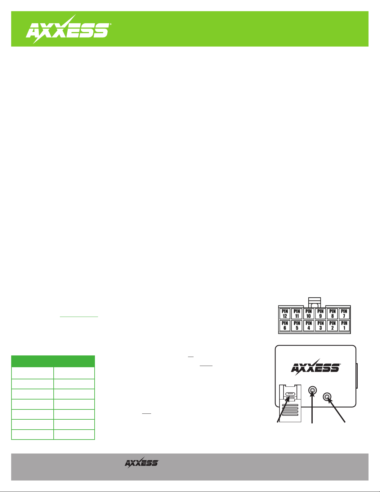
• For Metra Euro kits with an included AXSWC: The 3rd, 4th, 5th and 6th Red light flashes should be longer. If any of these flashes are not
longer, inspect that the following wires are connected (pin-out diagram shown to the right): Pin-4, Pin-5, Pin-8, Pin-11.
• If all steps have been performed and the light still doesn’t turn solid Red at the end of the programming sequence, update the interface to
the latest software via axxessinterfaces.com. After updating, program the inteface to the vehicle following the vehicle specific document.
If the interface still doesn’t turn solid Red at the end of the programming sequence, contact Tech Support at 386-257-1187
. Be prepared to
perform some tests in the vehicle when you contact Tech Support.
Keynotes
a.
Long Green light flashes represent wire(s) that
are
connected from the vehicle to the interface
.
b. Short Green light flashes represent wire(s) that
are not
connected from the vehicle
to the interface.
c.
Note that there will always be 7 Green flashes, in every application. What's
important is the length of the Green flashes. An example is data communication
vehicles. In these vehicles the 7th Green flash should be longer, indicating the Pink
wire is connected. Some may be confused by this process because it is assumed that
7 Green flashes total means the Pink wire is connected. This assumption is false. The
7th Green flash
must
be longer than the prior 6 Green flashes.
d. In data communication vehicles which require 2 wires (Blue/Pink & Pink)
connected to the interface, only the Pink wire will show up in LED feedback
.
e. In “press and hold” vehicles which require more than 1 wire connected to the
interface, only the primary wire will show up in LED feedback.
Vehicle LED Feedback (Green light)
Longer Light Flash AXSWC Wire
1 White/Green
2 Yellow/Green
3 Green/Orange
4 Gray/Red
5 Black/Green
6 Gray/Blue
7 Pink
Update Port Reset Button Programming LED
(Press and hold for
3 seconds, then release)