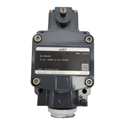
Azbil 5LX7 J Series User manual

Thank you for purchasing an Azbil
Corporation product.
This manual contains information for
ensuring the correct use of this prod-
uct. It also provides necessary informa-
tion for installation, maintenance, and
troubleshooting.
This manual should be read by those who
design and maintain equipment that uses
this product. Be sure to keep this manual
nearby for handy reference.
User’s Manual for Gas/Vapor
Explosion-Proof Increased-Safety
Limit Switches with “Ex d e IIC T6”
IECProtection for Outdoor Use:
5LX7___-J___ Increased-Safety
Conduit Type Limit Switches and
5LX7___-A1___/5LX7___-R___
Increased-Safety Packing-Type Limit
Switches
(TIIS)
No. CP-SP-1360E

NOTICE
Be sure that the user receives this manual before the product is used.
Copying or duplicating this user’s manual in part or in whole is forbidden.
The information and specifications in this manual are subject to change
without notice.
Considerable effort has been made to ensure that this manual is free from
inaccuracies and omissions. If you should find an error or omission, please
contact the azbil Group.
In no event is Azbil Corporation liable to anyone for any indirect, special or
consequential damages as a result of using this product.
© 2013-2017 Azbil Corporation All Rights Reserved.

i
Conventions Used in This Manual
The safety precautions explained in the following section aim to prevent injury to the operator and
others, and to prevent property damage.
WARNING Warnings are indicated when mishandling this product
might result in death or serious injury.
CAUTION
Cautions are indicated when mishandling this product
might result in minor injury to the user, or physical damage
to the product.
In describing the product, this manual uses the icons and conventions listed below.
Use caution when handling the product.
The indicated action is prohibited.
Be sure to follow the indicated instructions.
Handling Precautions:
Handling Precautions indicate items that the user should pay attention to when handling
the 5LX7.
Note: Notes indicate information that might benefit the user.
(1), (2), (3): Numbers within parentheses indicate steps in a procedure or parts of an explanation.
This indicates the item or page that the user is requested to refer to.

ii
Safety Precautions
WARNING
Be sure to use this limit switch within the ranges specified on page 1 for certified explosion-pro-
tected electrical equipment. Failure to do so may cause a serious accident.
To maintain explosion-proof performance, do not disassemble the limit switch, except for removing
the cover when wiring, or changing the direction of the lever or head. Otherwise it will not satisfy
explosion-proof specifications.
CAUTION
The environmental conditions for the safe use of this limit switch in hazardous atmospheres are de-
scribed in the product specification sheet. Use this limit switch within the allowable ranges for each
characteristic as stated in the specifications.
Check the limit switch periodically to make sure that it is operating normally.
If the cover or exterior of the limit switch has some abnormality (dent, large crack or tiny cracks, etc.)
replace the switch immediately. Failure to do so may result in an ineffective seal or loss of explosion-
proof performance.
Wiring should comply with“Recommended Practice for Explosion-Protected Electrical Installations
in General Industries.”

iii
Contents
Conventions Used in This Manual
Safety Precautions
Chapter 1. OVERVIEW 1
Features 1
Applicable laws and standards 1
Chapter 2. NAMES OF PARTS 2
Appearance and structure of the limit switch 2
Model selection table 2
Chapter 3. INSTALLATION AND ADJUSTMENT 4
Installation 5
How to change the head orientation 7
Chapter 4. WIRING 8
Chapter 5. ADJUSTMENT 11
Points to check before beginning operation 11
Adjustment 11
Chapter 6. MAINTENANCE AND INSPECTION 12
Check points for maintenance 13
Chapter 7. SPECIFICATIONS 14
This symbol indicates the presence of safety instructions.

Memo

1
Chapter 1.
OVERVIEW
Features
• This Increased-safety explosion-proof limit switch incorporates an internal
flameproof switch.
• Conforms to Japanese explosion-proof standards.
• The internal switch is the two-circuit double-break type.
• Can be used in hydrogen atmospheres.
• IP67 seal allows outdoor use.
Applicable laws and standards
WARNING
Be sure to use this limit switch within the ranges specified below for certified explosion-protected elec-
trical equipment. Failure to do so may cause a serious accident.
1.
This limit switch is certified as explosion-protected electrical equipment by
the Technology Institution of Industrial Safety (TIIS) in accordance with
“Recommended Practice for Explosion-Protected Electrical Installations in
General Industries” (2008 guidelines, which conform to international standards).
2. Explosion-proof structure d e (d: flameproof enclosure, e: increased-safety)
3.
Gas group and temperature class
IIC T6
4. Hazardous area classification Gas atmospheres in hazardous Zones 1 and 2
5. Operating temperature −10 to +60˚C
6. Operating humidity 45 to 85%RH
7. Storage temperature −10 to +60˚C (standard type)
−10 to +100˚C (H type)
−40 to +60˚C (L type)
−10 to +60˚C (if stored using protective plug(s))
8. Storage humidity range 98%RH max. (if stored using protective plug(s))
9. Protective structure IP54/IP67
10. Example of explosive gas classification
“Recommended Practice for Explosion-Protected Electrical Installations in General Industries”(2006, for gases and vapors)
Temperature class T1 T2 T3 T4 T5 T6
Explosive gas class Over 450°C Over 300 to 450°C Over 200 to 300°C Over 135 to 200°C Over 100 to 135°C Over 85 to 100°C
Explosion-protected electrical
equipment group
II
IIA
Acetone
Ammonia
Ethyl acetate
Benzene
Carbon monoxide
Methane
Methanol
Propane
Toluene
Ethanol
Vinyl chloride
Butyl acetate
Ethylbenzene
Dimethylamine
Propylene
Propan-1-ol
Butane
Methyl
methacrylate
Octane
Hexane
Cyclohexane
Butyl chloride
Pentane
1-Octanol
Gasoline
Kerosene
Naphtha
Acetaldehyde
Trimethylamine
Ethyl nitrite
IIB
Acrylonitrile
Hydrogen cyanide
Cyclopropane
Coke oven gas
Ethyl acrylate
Ethylene
Ethylene oxide
1,3-butadiene
Acrylic aldehyde
Crotonaldehyde
Dimethyl ether
Tetrahydrofuran
Ethyl methyl ether
Diethyl ether
Dibutyl ether
Tetrafluoroethylene
IIC Hydrogen Acetylene Carbon disulfide Ethyl nitrate
Note: Switches classified as IIC T6 can be used with a gas or vapor listed inside the bold lines.

2
Chapter 2.
NAMES OF PARTS
Appearance and structure of the limit switch
External force applied to the limit switch is transferred as follows: roller →external
plunger →internal plunger →internal switch, which opens or closes the electrical
circuit. The structure and names of parts are shown below.
Roller
Shaft
External plunger
Diaphragm seal
Label
Cover mounting screw
Head mounting screw
Conduit
Housing
Ground terminal screw
Plug
Plunger
Head
O-ring seal
Insulator
Internal switch
Cover
5LX7001-R
Model selection table
5LX7001-____
Basic model No. Conduit Contact material Environment Material Specifications
5LX7001- Actuator type: roller plunger
J G1/2 straight thread
(increased-safety conduit type)
A1 G1/2 straight thread packing-type cable gland
(increased-safety packing-type)
R Packing-type connector
(increased-safety packing-type)
None Silver (for standard loads)
K Gold-plated (for minute loads)
None Standard
H For tropical regions*1
L For cold regions*1
None Standard
M Corrosion-resistant*2
*1. See Applicable laws and standards (P.1) for temperature and humidity.
*2. Cannot be selected with A1.
Example: 5LX7001-RM
Conduit: Packing-type connector
(increased-safety packing-type)
Contact material: Silver
Environment: Standard
Material: Corrosion-resistant

3
Chapter 2. NAMES OF PARTS
Increased-safety conduit type:
2PA-JEXN16 nipple + SFT-16 sealing fitting made by Shimada Electric Co., Ltd.
Sealing fitting Nipple Limit Switch
Increased-safety packing-type:
EXPC-16B series packing-type cable gland made by Shimada Electric Co., Ltd.
Explosion-proof packing type cable grand Limit Switch
Increased-safety packing-type: 2PA-JEX _ _ _ PM series packing-type connector
Explosion-proof packing type connector Limit Switch

4
Chapter 3.
INSTALLATION AND ADJUSTMENT
This section describes how to install the limit switch.
WARNING
Never leave or use the limit switch when the cover is off. Doing so may cause an explosion resulting in
serious harm.
CAUTION
Do not remove the cover or the plug from the limit switch until you are ready to do the wiring. If dust
or liquid enters the switch, poor operation, poor electrical contact, or insulation failure may result.
After wiring is complete, do not leave the limit switch with its cover off. If dust or liquid enters the
switch, poor operation, poor electrical contact, or insulation failure may result.
Before using for the first time, keep the whole limit switch protected with a dustproof and waterproof
sheet. Substances like cement or paint stuck to the switch may cause the lever to malfunction.
Do not leave the limit switch in an atmosphere containing gases that can adversely affect the contacts
and/or other materials (H2S, SOx, etc.). Exposure to such gases can cause contact failure.
Do not allow the limit switch seal to come into contact with solvents (benzene, kerosene, alcohol, etc.)
that may adversely affect them. Contact may lead to poor functioning or insulation failure.
Do not stand on the limit switch, place heavy objects on it, or strike it. Never apply a force 5 times
greater than the operating force (O.F.) to the switch lever. Failure to observe these precautions may re-
sult in faulty operation.
Before using a sealing agent, locking agent, etc., on the conduit joint, make sure that it will not gener-
ate fumes that will damage the contacts.
Make use of heat insulating material, a shielding plate, etc., in mounting the limit switch so that its tem-
perature will not exceed the working temperature range as a result of radiant heat or heat conduction.
Take appropriate protective countermeasures if the limit switch is installed in a location subject to con-
tinuous vibration or impact.
5
Chapter 3. INSTALLATION AND ADJUSTMENT
Installation
Installation
For installation of the limit switch, use a mounting plate whose material, thickness,
and shape provide sufficient strength so that the operating force of the limit switch
cannot deform the plate. When installing the limit switch, use washers or the like to
prevent the mounting screws from coming loose. Tighten the mounting bolts to the
tightening torque shown below.
Mounting direction Screw size Tightening torque
Mounting by screwing from the front M5 hexagon socket bolts 5 to 6N·m
Mounting by screwing from the back M6 hexagon socket bolts 5 to 6N·m
Sealing fitting (for 5LX7_ _ _-J_ _ _ increased-safety conduit type limit switch)
Use the dedicated nipple and sealing fitting.
Handling Precautions
• Specifications sheet, AD17024E
Packing-type cable gland (for 5LX7 _ _ _ -A1 _ _ _ increased-safety packing-type limit switch)
Choose a packing-type cable gland from the EXPC-16B series made by Shimada
Electric Co., Ltd., making sure that is the correct size for the outer diameter of the
cable.
Handling Precautions
• If a packing-type cable gland that does not match the outer diameter
of the cable is used, poor explosion-proof performance could result.
Specifications sheet, AD18142E
Packing-type connector (for 5LX7 _ _ _ -R _ _ _ increased-safety packing-type limit switch)
Choose a packing-type connector from the 2PA-JEX _ _ _ PM series made by Azbil
Corporation, making sure that is the correct size for the outer diameter of the cable.
Handling Precautions
• If a packing-type connector that does not match the outer diameter of the
cable is used, poor explosion-proof performance could result.
2PA-JEX_ _ _PM Series Increased-Safety Packing-Type Connector for LX/
VCX Series Limit Switch User’s Manual, CP-UM-5717JE.

6
Chapter 3. INSTALLATION AND ADJUSTMENT
Dog angle check
V
30 30
V = 0.3 m/s MAX
V
aa
If the actuating object speed (V) is faster than
0.3m/s, set the actuating object angle (α) ac-
cording to the table below.
α V (m/s)
25° 0.4
20° 0.5
Handling Precautions
• The actuating object should not touch anything other than the roller.
• The actuating object should make contact with the full width of the roller.
Otherwise abnormal abrasion of the roller or faulty operation may occur.
Dog
OK
Dog
×
About the actuating object
The roughness and hardness of the object’s surface significantly affects the operat-
ing life of the switch. The following specifications are recommended.
Roughness Hardness
Approx. Ra 6.3 Approx. HV 450
Note
•If grease is applied to the sliding parts of the roller, actuating object, etc., they
will move more smoothly.
Overtravel and force
To ensure reliable operation, set overtravel (O.T.) between 1/3 to 2/3 of the over-
travel stated in the specifications.
Handling Precautions
• Do not apply excessive force (three times the O.F. or more) to the lever beyond
the operating limit position. Doing so may cause faulty operation.

7
Chapter 3. INSTALLATION AND ADJUSTMENT
How to change the head orientation
CAUTION
If the diaphragm seal gets out of place, be sure to put it back in
its original position around the plunger, as shown in the drawing
at right. If the head direction is changed or the head is removed,
the diaphragm seal may come loose.
Plunger
Diaphragm seal
Procedure
(1) Remove the head mounting screws.
(2) Change the direction of the head and reattach it.
(3) Tighten the head mounting screws according to the table below.
Tightening torque
1.3 to 1.7 N·m
Handling Precautions
• Do not tighten beyond the specified torque. Overtightening may damage the
screw threads, housing, etc.
• Make sure that the diaphragm seal is securely attached.

8
Chapter 4.
WIRING
This section describes wiring of the limit switch.
WARNING
Before wiring, turn the equipment power off. Depending on the voltage, failure to do so may result in
an electric shock.
CAUTION
Wiring should comply with“Recommended Practice for Explosion-Protected Electrical Installations in
General Industries.”
Securely attach the cover so that it tightly contacts the housing. If the cover is not well tightened, the
limit switch will not be effectively sealed.
Be sure to ground the limit switch using either the internal or external ground screw.
Do not use wire with silicone rubber insulation, or adhesive or grease which contains silicone. They can
cause contact failure in electrical contacts.
For connection to a conduit with G1/2 pipe thread, screw in to a depth of at least 5 threads, and secure
with a lock nut. If waterproofing is required, apply sealant to the screw threads. For explosion-proofing,
be sure to use a sealing fitting to connect the conduit to the switch, and apply sealing compound. For
waterproof applications, use liquid gasket or other sealant on the conduit threads.
Use wires or cables with a heat resistance to temperatures of 70°C or more.
Handling Precautions
• When wiring the terminal block, use wires whose nominal cross-sectional area
is 0.5–1.5mm2(20–16 AWG) or cables whose nominal cross-sectional area is
0.5–2.5mm2(20–14 AWG) together with M4 crimp terminals with insulating
sleeves (made by J.S.T. Mfg. Co., Ltd., or equivalent).
• The figure below shows the size of the crimp terminal.
8 max.
16 max.
• Make sure that the crimp terminals and wires do not touch the cover.
• Bend the insulated crimp terminals down. Otherwise, the cover will not close
properly.
Removing the cover
Remove the M5 hexagon socket bolts using a 4mm hexagon wrench.
M4 ring crimp terminal

9
Chapter 4. WIRING
Wiring of the limit switch
CAUTION
To wire the limit switch correctly, refer to the user’s manual or the product specification sheet.
• Tighten terminal screws to the torque shown below.
Screw size Tightening torque
M4 (pan head screw with square washer) 1.3 to 1.7 N·m
Wire routing
• Pull-out strength of the terminal
After wiring, do not pull the wire or cable with excessive force (≥ 30N).
30 (N) max.
Cable
Handling Precautions
•Do not exceed the values given for pulling force, which is the same for both
single wire and two-ply or more stranded wires.
Attaching the cover
Be sure to attach the cover after wiring is complete.
Tighten the four cover mounting screws evenly in a diagonal pattern.
Tighten the screws to the torque shown below.
Screw size Tightening torque
M5 (hexagon socket bolt with spring washer) 5 to 6 N·m
Handling Precautions
• When mounting the cover, make sure that it does not touch electrical wires or
terminals, and does not pinch the wiring insulation.
• Do not tighten beyond the specified torque. Overtightening may damage
screw threads of the housing.
Continuity tester
For a continuity check for the limit switch, use a tester whose measuring current
is 100mA or less.

10
Chapter 4. WIRING
Mounting a sealing fitting
(for 5LX7 _ _ _ -J _ _ _ increased-safety conduit type limit switch)
AD specifications sheet, AD17024E
Mounting a packing-type cable gland
(for 5LX7 _ _ _ -A1 _ _ _ increased-safety packing-type limit switch)
AD specifications sheet, AD18142E
Mounting a packing-type connector
(for 5LX7 _ _ _ -R _ _ _ increased-safety packing-type limit switch)
2PA-JEX_ _ _PM Series Increased-Safety Packing-Type Connector for LX/VCX
Series Limit Switch User’s Manual, CP-UM-5717JE.

11
Chapter 5.
ADJUSTMENT
Points to check before beginning operation
Check the following before using the limit switch.
(1) Wiring is correctly done.
(2) Limit switch mounting bolts, head mounting bolts, and cover mounting hexa-
gon socket bolts are tight.
(3) Conduit is well sealed using a sealed connector or flexible piping.
Adjustment
(1) To adjust the operating position of the limit switch, change the position of the
actuating object or of the limit switch.
(2) To ensure reliable operation, set overtravel (O.T.) to between 1/3 and 2/3 of the
value stated in the specifications.
Handling Precautions
• Do not apply excessive force (3 times the O.F. or more) to the actuator beyond
the operating limit position. Doing so may result in faulty operation.
• Do not attempt to move the actuator beyond the operating limit.

12
Chapter 6.
MAINTENANCE AND INSPECTION
WARNING
Be sure to use this limit switch within the ranges specified on page 1 for certified explosion-protected
electrical equipment. Failure to do so may cause a serious accident.
CAUTION
After inspecting the limit switch, firmly tighten the cover and conduit.
Insufficient tightening because of corrosion, etc., not only results in the loss of sealing and insulating
performance, but also nullifies the switch’s explosion-proofing.
Individual parts of this limit switch cannot be replaced. Replace the entire switch.
To ensure safe use the limit switch must be inspected periodically.
Adjust the frequency of inspection depending on the service conditions.

13
Chapter 6. MAINTENANCE AND INSPECTION
Check points for maintenance
The table below shows check points for maintenance of the limit switch. Because
the service life of this switch is five years, in general the switch should be replaced
every five years. However, the service life varies depending on the application
environment.
Equipment required for inspection
•Screwdriver •Insulation resistance tester •Adjustable wrench
•Continuity tester •Hex wrench (Allen wrench)
#Area Items Inspection Method Corrective Action Frequency
1 Roller
plunger
•
Damage to the plunger
•Roller rotation
•Use visual and other means
to check for damage to the
plunger, poor roller rota-
tion, etc.
•Replace the limit switch. Basically every
6months, but
whenever
there is an
opportunity
2 Head •Loose head mounting
screws
•External damage
•Check visually, etc., for
loose head mounting
screws.
•Check for damage to the
head.
•Tighten mounting screws if
they are loose. (See chap.3
(P.7) for tightening torque.)
•In other cases, replace the limit
switch.
3Cover •Loose cover mounting
screws
•External damage
•Check visually, etc., for
loose cover mounting
screws.
•Check for damage to the
cover.
•Tighten mounting screws if
they are loose. (See chap.4
(P.9) for tightening torque.)
•In other cases, replace the limit
switch.
4 Housing •External damage •Visually check for damage. •Replace the limit switch. Every 2years
5 Internal
switch
•Electrical continuity •Check the electric continu-
ity of all terminals using a
continuity tester.
Basically every
6 months, but
whenever
there is an
opportunity
•Isolation •Check all terminals using
an insulation resistance
tester.
•Loose screws
•Corrosion
•Check for loose terminal
screws, damage, rust, etc.
•Tighten terminal screws if they
are loose. (See chap.4 (P.9)
for tightening torque.)
6 Operation
check
•Operation check •Check the overtravel. •Readjust the overtravel.
•Check by hand that the
plunger and roller move
smoothly.
•Replace the limit switch.
7 Nipple and
sealing fitting
•Loose nipple or sealing
fitting
•Check nipple and sealing
fitting for looseness.
•Tighten nipple and/or sealing
fitting.
8 Packing-type
cable gland
•Loose cable gland •Check for cable gland
looseness.
•Loose cable •Check for cable looseness.
9 Packing-type
connector
•Loose connector •Check for connector
looseness.
•Loose cable •Check for cable looseness.
Note: The internal parts of this limit switch cannot be replaced. Replace the entire limit switch.

14
Chapter 7.
SPECIFICATIONS
For detailed limit switch specifications, see the specifications sheet. The relevant specifications sheet numbers are
shown below. To acquire them, contact the azbil Group.
Model No. Specifications sheet No.
5LX700_-_ _ _ _ AD18142E
2PA-JEX_ _ _PM AD17216E
2PA-JEXN_ _ AD17024E
This manual suits for next models
2
Table of contents
Other Azbil Switch manuals

Azbil
Azbil HPQ-D11 User manual

Azbil
Azbil LJS-A Series User manual

Azbil
Azbil C6097A User manual

Azbil
Azbil VCL-5 Series User manual

Azbil
Azbil FL7M Series User manual

Azbil
Azbil MagneW 3000 FLEX User manual

Azbil
Azbil H2B User manual

Azbil
Azbil NX-SWA User manual

Azbil
Azbil CP-UM-3138E User manual

Azbil
Azbil HP7 Series User manual
Popular Switch manuals by other brands

Cabletron Systems
Cabletron Systems MicroMMAC 22ES reference guide

StarTech.com
StarTech.com SV221HUC4K quick start guide

Alcatel-Lucent
Alcatel-Lucent OmniSwitch 9900 Series Network configuration guide

Shinybow USA
Shinybow USA SB-5612 instruction manual

Lumens
Lumens VS-LC102 user manual

LEGRAND
LEGRAND 4 130 09 instruction manual