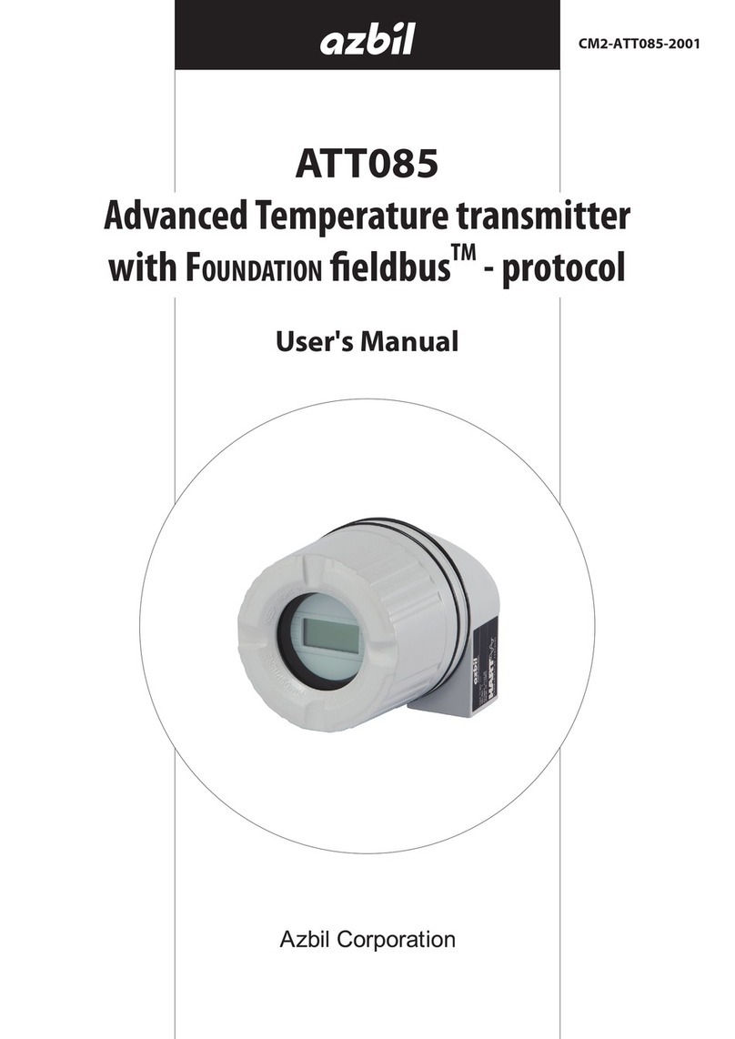
Azbil ATT085 User manual

ATT085
Advanced Temperature Transmitter
with FOUNDATION fieldbus™ - protocol
Brief User’s Manual
CM2-ATT085-2002

NOTICE
While the information in this manual is presented in good faith and
believed to be accurate, Azbil Corporation disclaims any implied
warranty of merchantability or fitness for a particular purpose and
makes no express warranty except as may be stated in its written
agreement with and for its customer.
In no event shall Azbil Corporation be liable to anyone for any
indirect, special or consequential damages. This information and
specifications in this document are subject to change without
notice.
These Instructions are Brief User’s Manual.
For detailed information, refer to the User’s Manual and other
documentation. These Brief User’s Manual do not act as a substitute
for the User’s Manual included in the scope of delivery.
©2015–2016 Azbil Corporation All Rights Reserved.

i
Safety
■Precautions for Use
For safe use of the product, the following symbols are used in this manual.
WARNING Warnings are indicated when mishandling the product
might result in the death or serious injury of the user.
CAUTION Cautions are indicated when mishandling the product
might result in minor injury to the user or damage to
property.
In describing the product, this manual uses the icons and conventions listed below.
Use caution when handling the product.
The indicated action is prohibited.
Be sure to follow the indicated instructions.
Handling Precautions:
Handling Precautions indicate items that the user should pay attention to
when handling the ATT085.
To use this product correctly and safely, always observe the following precautions.
We are not responsible for damage or injury caused by the use of the product in violation
of these precautions.

ii
■Handling Precautions for This Product
Installation Precautions
WARNING
When installing, use proper fittings and proper tightening torque for connections to
the process and to the exhaust. Gas leakage is dangerous because process gas and
calibration gas are flammable. Please refer to the leak check instructions in this
manual and verify that there is no gas leakage.
Do not use the product except at the rated pressure, specified connection standards,
and rated temperature. Use under other circumstances might cause damage that
leads to a serious accident.
For wiring work in an explosion-proof area, follow the work method stated in the
explosion-proof policy.
CAUTION
After installation, do not step or stand on this unit. Doing so may damage the device
or cause injury.
Bumping the glass of the display with a tool may cause damage or injury. Be careful.
Install the device correctly. Incorrect or incomplete installation will cause output
errors and violation of regulations.
This product is quite heavy. Protect your feet with safety shoes when working.
Do not subject the product to shock or impact.
Wiring Precautions
WARNING
Do not do wiring work with wet hands or while electricity is being supplied to the
product. There is a danger of electric shock. When working, keep hands dry or wear
gloves, and turn off the power.
CAUTION
When wiring, check the specifications carefully and make sure to wire correctly.
Incorrect wiring can cause device damage or malfunction.
Supply electric power correctly according to the specifications. Supplying power that
differs from the specifications can damage the device.
Use a DC power supply that has overload protection.

iii
Maintenance Precautions
WARNING
When removing this device for maintenance, be careful of residual pressure or
residual process gas. Leakage of process gas is dangerous.
When working on the vent, check its direction so that people do not come into
contact with vented gas. There is a danger of burns or other physical harm.
When the device is being used in an explosion-proof area, do not open the cover.
Opening the cover may cause an explosion.
CAUTION
This product was kept under carefully controlled conditions until it was shipped.
Never try to modify this device. Doing so could damage it.

iv

v
Table of Contents
Chapter 1. Identification ..........................................................1
1-1. Nameplate The right device? ...........................................................1
1-2. Scope of delivery ......................................................................1
1-3. Certificates and approvals .............................................................2
1-3-1. CE mark, declaration of conformity ..............................................2
1-3-2. Certification FOUNDATION Fieldbus™ ..............................................2
1-3-3. Korea Certification Mark .........................................................2
Chapter 2. Installation instructions ................................................3
2-1. Incoming acceptance, transport, storage ...............................................3
2-1-1. Incoming acceptance ...........................................................3
2-1-2. Transport and storage ..........................................................3
2-2. Installation conditions .................................................................3
2-2-1. Dimensions .....................................................................3
2-2-2. Installation point ...............................................................3
2-2-3. Important ambient conditions ..................................................3
2-3. Installation instructions ................................................................4
2-3-1. Mounting typical of Europe .....................................................4
2-4. Post-installation check .................................................................4
Chapter 3. Wiring .................................................................5
3-1. Quick wiring guide .....................................................................5
3-2. Connecting the sensor cables ..........................................................6
3-3. Connecting the power supply and signal cables.........................................6
3-3-1. Cable glands or entries ..........................................................6
3-3-2. Shielding and grounding ........................................................7
3-4. Post-connection check .................................................................8
Chapter 4. Operation and commissioning .........................................9
4-1. Function check ........................................................................9
4-2. Display and operating elements (optional) .............................................9
4-2-1. Display..........................................................................9
4-2-2. Display symbols ................................................................9
4-3. Configuration of the head transmitter and FF functions ................................10
4-4. Hardware settings (DIP switches) ......................................................10
4-5. Switching on the head transmitter ....................................................11
Appendix A. Explosion protected models......................................... 13
A-1. FM intrinsically safe, nonincendive and suitable approvals..............................13
Terms and Conditions
vi

1
Chapter 1 Identication
Chapter 1. Identification
1-1. Nameplate The right device?
Compare and check the details on the device nameplate against the measuring point
requirements.
1 6
2
35
0DFC9602-
ATT08 5 -
4
Figure 1-1. Nameplate of the head transmitter (example, Ex version)
1. Device identication number (Device_ID)
2. Power supply and extended order code
3. Serial number and FW release
4. Tag name (TAG)
5. Approval in hazardous area with number of the relevant Ex documentation
6. Order code
1-2. Scope of delivery
The scope of delivery of the device comprises:
• Temperature head transmitter - display as option
• Securing material
• Multilingual hard copy of Brief User's Manual
Note: Please note the accessories of the device in the chapter “accessories” from the User's
Manual.

2
Chapter 1 Identication
1-3. Certificates and approvals
On leaving the factory, the device was in perfect condition from the point of view of safety.
The device complies with the standards EN61010-1 “Protection Measures for Electrical
Equipment for Measurement, Control, Regulation and Laboratory Procedures” and with
the EMC requirements of IEC/EN61326.
1-3-1. CE mark, declaration of conformity
The device meets the legal requirements of the EU Directives. The manufacturer confirms
a positive completion of all tests by fitting the unit with a CE mark.
1-3-2. Certification FOUNDATION Fieldbus™
The device meets all the requirements of the following specifications:
• Certified in accordance with FOUNDATION Fieldbus™specification
• FOUNDATION Fieldbus™H1
• Interoperability Test Kit (ITK), (device certification number available on request): the
device may also be operated using certified devices from other manufacturers
• Physical Layer Conformance Test of the Fieldbus FOUNDATION™
An overview of other approvals and certificates can be found in the User's Manual.
1-3-3. Korea Certification Mark

3
Chapter 2 Installation instructions
Chapter 2. Installation instructions
2-1. Incoming acceptance, transport, storage
2-1-1. Incoming acceptance
On receipt of the goods, check the following points:
• Are the contents or the packaging damaged?
• Is the delivery complete and is anything missing? Check the scope of delivery against
your order.
2-1-2. Transport and storage
Note the following points:
• Pack the device in such a way as to protect it reliably against impact for storage (and
transportation).
• The permitted storage temperature is −40 to +100°C (−40 to 212°F).
2-2. Installation conditions
2-2-1. Dimensions
Dimensions in mm (in)
)59.0(1.42
)3.1(33
B
C
A
Figure 2-1. Version with screw terminals
Item A: Spring travel L 0.5mm (not for US - M4 securing screws)
Item B: Securing elements for attachable measured value display
Item C: Interface for measured value display contact
Note: The same dimensions apply for the version with spring terminals apart from the
housing height H = 28.1mm (1.11in).
2-2-2. Installation point
• In the terminal head as per DIN EN 50446, flat face, direct mounting on insert with
cable entry, middle hole 7mm (0.28in).
• Separate from the process in the field housing.
• With DIN rail clip on top-hat rail as per IEC60715.
2-2-3. Important ambient conditions
• Ambient temperature range: −40 to +85°C (−40 to +185°F).
• Condensation permitted as per IEC60068-2-33; max. rel. humidity: 95%
• Climate class in accordance with IEC 60654-1, Class C
•
IP 00 ingress protection, depends on the terminal head or field housing in its installed state

4
Chapter 2 Installation instructions
2-3. Installation instructions
A screwdriver is needed to mount the head transmitter.
Handling Precautions:
Damage of the head transmitter
>> Do not overtighten the mounting screws.
Maximum torque = 1N·m (3/4 pound-feet).
2-3-1. Mounting typical of Europe
Figure 2-2. Head transmitter mounting (three versions)
Mounting in a field housing
Procedure:
1. Open the cover (1) of the field housing (5).
2. Guide the mounting screws (2) through the lateral bores of the head transmitter (3).
3. Screw the head transmitter to the field housing.
4. When wiring is complete (Refer to page 5), screw the field housing cover (1) back on.
2-4. Post-installation check
After installing the device, always run the following final checks:
Device condition and specifications Notes
Has the device been mounted in accordance with specifications? (Refer to page 3)
Is the device free of damage? Visual check
Handling Precautions:
Make sure the sensor type.
Make sure that the sensor type and model are correct.
Use of the incorrect sensor and model might cause temperature errors or
abnormal outputs.

5
Chapter 3 Wiring
Chapter 3. Wiring
CAUTION
Switch o power supply before installing or connecting the device. Failure to
observe this may result in destruction of parts of the electronics.
When installing Ex-approved devices in a hazardous area please take special note of
the instructions and connection schematics in the respective Ex documentation
added to these User's Manual. Your supplier is available for assistance if required.
Do not occupy the display connection. An incorrect connection can destroy the
electronics.
A Phillips head screwdriver is required to wire the head transmitter with screw terminals.
Handling Precautions:
Do not overtighten the screw terminals, as this could damage the transmitter.
>> Maximum torque = 1N·m (3/4pound-feet).
For wiring a mounted head transmitter, proceed as follows:
1. Open the cable gland and the housing cover on the terminal head or the eld housing.
2. Feed the cables through the opening in the cable gland.
3. Connect the cables as shown in 3-1.
4. Retighten the cable gland and close the housing cover.
5. In order to avoid connection errors, prior to commissioning always follow the instructions given in
the section on the post-connection check.
3-1. Quick wiring guide
Terminal assignment
Figure 3-1. Wiring the head transmitter

6
Chapter 3 Wiring
3-2. Connecting the sensor cables
Handling Precautions:
When connecting 2 sensors ensure that there is no galvanic connection
between them. The resulting equalizing currents distort the measurements
considerably. The sensors must be galvanically isolated from one another
by connecting each sensor separately to a transmitter. The device provides
sufficient galvanic isolation (>2kVAC) between the input and output.
The following connection combinations are possible when both sensor inputs are assigned:
Sensor input 1
RTD or resistance transmitter Thermocouple (TC),
voltage transmitter
2- wire 3- wire 4- wire
Sensor
input 2
RTD or
resistance
transmitter
2-wire ✓ ✓ —✓
3-wire ✓ ✓ —✓
4-wire — — — —
Thermocouple (TC),
voltage transmitter ✓ ✓ ✓ ✓
3-3. Connecting the power supply and signal cables
Fieldbus cable specications to IEC 61158-2 (MBP), for details, see User’s Manual. Devices
can be connected to the eldbus in two ways:
• Connection via conventional cable gland.
• Connection via fieldbus connector (optional, can be purchased as an accessory).
Note: Grounding via one of the grounding screws (terminal head, field housing) is
recommended.
3-3-1. Cable glands or entries
Figure 3-2. Connection to the eldbus cable - installed in the eld housing on the left,
and in the terminal head on the right
1. Fieldbus terminals - eldbus communication and power supply
2. Inner ground terminal
3. Outer ground terminal
4. Shielded eldbus cable

7
Chapter 3 Wiring
• The terminals for the fieldbus connection (1+ and 2−) are not polarity sensitive.
• Conductor cross-section:
• Max. 2.5mm2for screw terminals
• Max. 1.5mm2for spring terminals. Minimum stripping length of wire = 10mm
(0.39in)
• A shielded cable must be used for the connection.
3-3-2. Shielding and grounding
Optimum electromagnetic compatibility (EMC) can only be guaranteed if the system
components and, in particular, the lines are shielded and the shield forms as complete a
cover as possible.
The fieldbus system allows three different types of shielding:
• Shielding at both ends
• Shielding at one end on the feed side with capacitance termination at the field device
• Shielding at one end on the feed side
With regard to EMC, the best results are achieved in most cases with one-sided shielding
on the feed side (no capacitance connection to the field device). Operation in the event of
disturbance variables as per NAMUR NE21 is thus guaranteed.
Figure 3-3. Shielding and one-sided grounding of the fieldbus cable shielding
1. Supply unit
2. Distribution box (T-box)
3. Bus terminator
4. Grounding point for eldbus cable shielding
5. Optional grounding of the eld device, isolated from cable shielding.

8
Chapter 3 Wiring
3-4. Post-connection check
Device condition and specications Notes
Are the device or the cables free of damage (visual
check)? --
Electrical connection Notes
Does the supply voltage match the specifications on the
nameplate? 9 to 32 V DC
Do the cables used comply with the fieldbus specificati-
ons? See User's Manual
Do the cables have adequate strain relief? --
Are the power supply and signal cables correctly con-
nected?
See the connection diagram on
the top of the head transmitter
Are all the cable entries installed, tightened and sealed? --
Are all the housing covers installed and tightened? --
Electrical connection of FOUNDATION Fieldbus™Notes
Are all the connecting components (T-boxes, junction
boxes, connectors, etc.) connected with each other cor-
rectly?
--
Has each fieldbus segment been terminated at both ends
with a bus terminator? --
Has the max. length of the fieldbus cable been observed
in accordance with the ¥fieldbus specifications? --
Has the max. length of the spurs been observed in accor-
dance with the fieldbus specifications? --
Is the fieldbus cable fully shielded and correctly groun-
ded? (Refer to page 7.)

9
Chapter 4 Operation and commissioning
Chapter 4. Operation and commissioning
4-1. Function check
Prior to commissioning, please ensure that:
• The device has been mounted correctly.
• The electrical connection is correct.
4-2. Display and operating elements (optional)
Option: display with transmitter.
Figure 4-1. Fit the display on the transmitter
4-2-1. Display
1
2
3
4
5
6
7
Figure 4-2. LC display of the head transmitter
4-2-2. Display symbols
Item No. Function
1 Display TAG (32 characters)
2 Display “Communication” symbol for read and write access
3 Display unit (°C, °F)
4 Measured value display
5 Channel display C1 or C2, P1, S1 or P2, S2, RJ
6 Display the “Configuration locked” symbol when configuration is locked
via the hardware.
7 Warning or error message
Warning: warning code and measured value alternate
Error: error code and “-- - .” (no measured value)
Detailed instructions are provided in the User's Manual.

10
Chapter 4 Operation and commissioning
4-3. Configuration of the head transmitter and FF functions
The FF communication system will only function properly if correctly configured. You can
obtain special configuration and operating programs from various manufacturers for the
configuration.
Note: A detailed step-by-step description of the procedure for commissioning the FF
functions, together with information on configuring device-specific parameters, is
given in the User's Manual.
System files
You require the following files for commissioning and configuring the network:
• Commissioning → DD (Device Description: *.sym, *.ffo, *.sy5, *.ff5 files)
• Network configuration → *.cff file (Common File Format)
These files can be acquired as follows:
• Free of charge via the Internet: www.azbil.com
• Via the FOUNDATION Fieldbus™organization: www.fieldbus.org
4-4. Hardware settings (DIP switches)
DIP switches on the rear of the display are used to enable and disable hardware write
protection and the simulation mode (for the Analog Input Block), and to switch (turn) the
display 180°.
When write protection is active, parameters cannot be modified.
The simulation mode via the hardware setting must be changed before the software setting.
To set the DIP switches, proceed as follows:
1. Remove the attached display from the head transmitter.
2. Congure the DIP switch on the rear of the display accordingly. Generally: switch to ON = function
enabled, switch to OFF = function disabled.
3. Fit the display onto the head transmitter in the correct position. e head transmitter accepts the
settings within one second.
Figure 4-3. Hardware settings via DIP switches
1. Connection to head transmitter
2. DIP switch (1-64, SW/HW and ADDR ACTIVE), no function
3. DIP switch (SIM = simulation mode; WRITE LOCK = write protection; DISPL. 180° = switch
(turn) the display 180°)

11
Chapter 4 Operation and commissioning
4-5. Switching on the head transmitter
Once the final checks have been successfully completed, it is time to switch on the supply
voltage. The head transmitter performs a number of internal test functions after power-up.
As this procedure progresses, the following sequence of messages appears on the display:
Step Display
1 Display and its firmware version (FW)
2 Company logo
3 Device name as well as the FW, HW and device release of the head transmitter
4 Displays sensor configuration
5 Current measured value or
Current status message
If the switch-on procedure fails, the appropriate status message is displayed, de-
pending on the cause. A detailed list of the status messages, as well as the mea-
sures for troubleshooting, can be found in the User's Manual.
The device is operational after approx. 8seconds and the attached display after approx.
16seconds. Normal measuring mode commences as soon as the switch-on procedure is
completed. Various measured values and/or status values appear on the display.
For a more detailed temperature transmitter configuration description and further
information, please refer to the User's Manual.

12
Chapter 4 Operation and commissioning
Other manuals for ATT085
1
Table of contents
Other Azbil Transmitter manuals

Azbil
Azbil MagneW Plus+ MGG14C User manual

Azbil
Azbil PREX3000 User manual

Azbil
Azbil ATT085 User manual

Azbil
Azbil ATT082 Instructions for use

Azbil
Azbil ATT082 User manual

Azbil
Azbil KDP Series User manual

Azbil
Azbil PTG71 User manual

Azbil
Azbil SLX 110 User manual

Azbil
Azbil JTD720A User manual

Azbil
Azbil PTG60 User manual