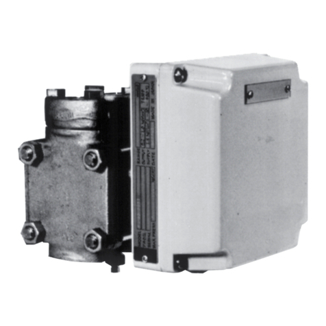
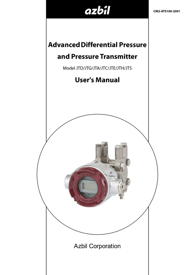
Azbil SLX 110 User manual

Smart Displacement type
Level Transmitter
Model SLX 110/120
User’s Manual
CM2-SLX100-2001

Copyright, Notices and Trademarks
© 2001-2020 Azbil Corporation. All Rights Reserved.
While this information is presented in good faith and believed to be
accurate, Azbil Corporation disclaims the implied warranties of mer-
chantability and tness for a particular purpose and makes no express
warranties except as may be stated in its written agreement with and for
its customer.
In no event is Azbil Corporation liable to anyone for any indirect, spe-
cial or consequential damages. is information and specications in
this document are subject to change without notice.

ank you for purchasing the Azbil Corporation smart displacement
type level transmitter.
Model SLX110/120 oers high performance and highly reliable level
transmitters with a microprocessor incorporated in each one.
Most operations such as starting measurement, reading of measured
data, check or change of various set values and setting condition, etc.
can be easily performed by using the smart communicator SFC.


Model SLX 110/120 - Smart displacement type level transmitter i
Safety
About this manual
Correct installation, operation and periodic maintenance are essential to the safe use
of this instrument. Carefully read the safety precautions described in this instruction
manual and have a thorough understanding before starting installation, operation or
maintenance.
When you receive the product, check to see if it is of the correct specications or
if there is any damage caused by transportation. This instrument is shipped after
being tested according to a strict quality control program. If you nd any omissions
in aspects of quality and specications, inform us of the model number and product
number described on the identication plate.
The identication plate is attached to the transmitter part.
WARNING
Indicates a potentially hazardous situation that may result in death or serious injury in
the event of improper handling.
CAUTION
Indicates a potentially hazardous situation that may result in light to moderate injuries
or only in property damage in the event of improper handling.
For correct and safe use of the instrument, be sure to observe the cautions described
on the following pages. Azbil Corporation will not be responsible for any damage that
is a result of handling of the product against these cautions.

Safety Azbil Corporation
ii Model SLX 110/120 - Smart displacement type level transmitter
Safety precautions
Cautions on installation
WARNING
• Do not use the instrument beyond the rated pressure, connection specication and
rated temperature specied for the instrument. This may result in serious accident
due to damage.
• Wiring in an explosion-proof area should be performed according to the work
procedure specied in the explosion-proof guideline.
CAUTION
• After installation, do not use this instrument as a foothold, etc. This may damage
the instrument or may result in physical injury
• Avoid hitting the glass part of the display with tools. This may damage the glass
and result in physical injury.
• Perform installation correctly. Insucient installation or no installation may result
in output errors or violate applicable regulations.
• This product is heavy. Pay attention to the scaolding and wear safety shoes.
Cautions on wiring
WARNING
Do not perform wiring with wet hands or with power turned on. This may result in
electrical shock. Work with dry hands or wear gloves and turn o power.
CAUTION
• Carefully check the specications and perform wiring correctly. Incorrect wiring
may damage the instrument or cause mis-operation.
• Use a power supply that conforms to the specications. Using the wrong power
supply may damage the instrument.

Azbil Corporation Safety
Model SLX 110/120 - Smart displacement type level transmitter iii
Cautions on maintenance
WARNING
• When removing this instrument from the process for maintenance, be especially
careful of residual pressure or any residual uid remaining in the process line or in
the instrument.
• When carrying out venting or draining, check the direction of venting or draining
and prevent it from coming into contact with the human body. This may result in
burns or physical injury.
• When the instrument is used in an explosion-proof area, do not leave the
transmitter part uncovered for fear of sparks or ignition.
CAUTION
This instrument is shipped under strict product control by Azbil Corporation. Do not
modify the instrument under any circumstances as this may damage the instrument.
Cautions on use of communication devices
CAUTION
Using a transceiver, cellular phone, pager, etc. near this instrument may prevent the
instrument from functioning correctly depending on the transmission frequency being
used. Observe the following precautions.
• Check beforehand the distance at which the communication device will not aect
the operation of this instrument and use the communication device at a greater
distance.
• Use the communication device after putting the cover on the transmitter part.

iv Model SLX 110/120 - Smart displacement type level transmitter

Table of Contents
Chapter 1 : Installation
1-1 : Names of components and parts.................................................................. 1-1
1-2 : Safety precautions ........................................................................................ 1-4
1-3 : Specications................................................................................................ 1-4
1-4 : Installation condition ..................................................................................... 1-4
Installation standard of explosion-proof type.............................................. 1-5
1-5 : Unpacking and storage................................................................................. 1-6
Unpacking .................................................................................................. 1-6
Checking instrument .................................................................................. 1-6
Checking specication ............................................................................... 1-7
Storage....................................................................................................... 1-7
1-6 : Installation method........................................................................................ 1-9
External type .............................................................................................. 1-9
Internal type ............................................................................................... 1-9
Heat insulation ........................................................................................... 1-10
Main unit, oat mounting procedure........................................................... 1-10
In case of external type (* when oat is set after main unit is xed).. 1-11
In the case of internal type (when oat is set before main unit is xed)
1-16
Flange bolt tightening torque ............................................................. 1-16
Electrical wiring .......................................................................................... 1-18
Wiring for waterproof model............................................................... 1-18
Wiring for explosion-proof model....................................................... 1-20
Chapter 2 : Operation
2-1 : Principles of operation .................................................................................. 2-1
2-2 : Indicator (optional) ........................................................................................ 2-3
Component part names of indicator ........................................................... 2-3
Digital display ............................................................................................. 2-3
Analog bar graph display ........................................................................... 2-4
Display during external adjustment switch operation ................................. 2-4
2-3 : Items to be checked before operation .......................................................... 2-5
General checking procedure ...................................................................... 2-5
Checking set data ...................................................................................... 2-6
SFC connections ............................................................................... 2-6
Communication start.......................................................................... 2-7
Checking set data.............................................................................. 2-8
Printing example................................................................................ 2-9
Zero span adjustment ................................................................................ 2-10
When liquid level in chamber (liquid tank)
can be changed up to upper limit ..................................................... 2-10
When adjusting zero point to output value according to real level .... 2-16

Table of Contents
2-4 : Operation start .............................................................................................. 2-18
Before operation start................................................................................. 2-18
Start operation............................................................................................ 2-18
When steady operation is reached............................................................. 2-18
2-5 : Operation stop .............................................................................................. 2-19
2-6 : Operation using SFC .................................................................................... 2-19
Principles of key operation ......................................................................... 2-19
Interaction with screen ............................................................................... 2-20
Correction of input ............................................................................. 2-20
SFC keyboard ............................................................................................ 2-21
Basic operation of key input ....................................................................... 2-22
SFC key functions ...................................................................................... 2-23
Green key functions........................................................................... 2-24
Orange key functions......................................................................... 2-26
Yellow key functions .......................................................................... 2-28
Dark green key functions................................................................... 2-30
White key functions............................................................................ 2-31
Dedicated functions.................................................................................... 2-32
Operation when starting measurement ..................................................... 2-32
Display measured data .............................................................................. 2-33
Liquid level input (mm)....................................................................... 2-33
Output being transmitted (%)............................................................. 2-33
Torque tube temperature (°C) ........................................................... 2-33
Angle sensor temperature (°C).......................................................... 2-35
Input angle......................................................................................... 2-36
Displaying and changing set data for measurement .................................. 2-37
Lower range value (LRV)................................................................... 2-37
Upper range value (URV) .................................................................. 2-40
Span .................................................................................................. 2-41
Specic gravity................................................................................... 2-42
Torque tube temperature coecient.................................................. 2-44
Range ................................................................................................ 2-46
Oset angle ....................................................................................... 2-48
Material coecient............................................................................. 2-50
Damping time constant...................................................................... 2-52
Printing ....................................................................................................... 2-53
How to feed recording paper ............................................................. 2-53
Maintenance printout ......................................................................... 2-54
Action printout.................................................................................... 2-56
Display and change of setting of this instrument........................................ 2-58
Changeable and non-changeable data ............................................. 2-58
Tag No............................................................................................... 2-59
Serial number .................................................................................... 2-60
Software version................................................................................ 2-61
Indicator display format...................................................................... 2-62
Table of Contents
Engineering unit value ....................................................................... 2-63
Burnout direction................................................................................ 2-65
DE output format ........................................................................................ 2-67
Output signal mode setting................................................................ 2-67
Information quantity setting................................................................ 2-67
Fail-safe mode setting ....................................................................... 2-67
Constant current source mode................................................................... 2-68
Constant current source mode setting............................................... 2-68
Cancellation of constant current source mode .................................. 2-69
Memo recording ......................................................................................... 2-69
Writing to scratch pad 1..................................................................... 2-69
Writing to scratch pad 2..................................................................... 2-72
Charging SFC ............................................................................................ 2-72
Procedure .......................................................................................... 2-73
2-7 : Operation of external adjustment switch (with indicator) .............................. 2-74
Basic operation method ............................................................................. 2-74
Function ..................................................................................................... 2-74
Operation procedure .................................................................................. 2-75
Zero adjustment to adjust to real level (pinpoint adjustment) ............ 2-75
Damping adjustment.......................................................................... 2-76
Zero span adjustment........................................................................ 2-76
Zero adjustment................................................................................. 2-77
Span adjustment................................................................................ 2-78
Operation sequence .......................................................................... 2-79
Chapter 3 : Maintenance
3-1 : Daily maintenance items............................................................................... 3-1
Visual inspection ........................................................................................ 3-1
Zero adjustment ......................................................................................... 3-1
3-2 : Items of periodic maintenance check ........................................................... 3-2
Verication of functions .............................................................................. 3-2
Disassembly and cleaning of wetted parts................................................. 3-2
Primary disassembly/cleaning
(when inside of torque tube housing is not cleaned) ......................... 3-2
Secondary disassembly/cleaning (cleaning inside of torque tube
housing)............................................................................................. 3-4
Reassembly, reinstallation................................................................. 3-5
Handling of torque tube ..................................................................... 3-6
Inspection of instrument ............................................................................. 3-6
Zero and span adjustment ......................................................................... 3-7
3-3 : When output shift is large ............................................................................. 3-8
Adjustment ................................................................................................. 3-8
3-4 : Zero span calibration with weight ................................................................. 3-12
Dierence between adjustment and calibration ......................................... 3-12

Table of Contents
Adjustment (key sequence [SET], [ENTER]):.................................... 3-12
Calibration (key sequence [CORRECT], [ENTER]):.......................... 3-12
Procedure for calibration with weight ......................................................... 3-13
3-5 : Calibrating output signal ............................................................................... 3-17
Instruments used........................................................................................ 3-17
Setup.......................................................................................................... 3-17
Calibrating output signal 0% ...................................................................... 3-18
Calibrating output signal 100% .................................................................. 3-20
Saving calibrated values and canceling constant current source mode .... 3-22
3-6 : Returning all set data to factory settings....................................................... 3-23
3-7 : Insulation resistance test and withstand voltage test.................................... 3-24
Test procedure ........................................................................................... 3-24
Judgment criteria........................................................................................ 3-24
3-8 : Replacement parts and recommended replacement cycle........................... 3-25
Replacement parts list................................................................................ 3-25
Table for selection of chamber-bonnet gasket parts ................................. 3-26
Recommended replacement cycle............................................................. 3-27
Replacing terminal block with indicator (LCD) ........................................... 3-27
3-9 : Starting instrument after maintenance.......................................................... 3-29
Chapter 4 : Repair
4-1 : Using dedicated apparatus necessary for repair .......................................... 4-2
4-2 : Troubleshooting ............................................................................................ 4-2
Operation check ......................................................................................... 4-2
When error occurs during communication ................................................. 4-3
Self-diagnostic message ............................................................................ 4-4
When this instrument is suspected to
involve error (serious fault or light fault)............................................. 4-4
Indicator (option) error messages .............................................................. 4-8
Self-diagnostics upon power-up ........................................................ 4-8
Self-diagnostics during normal operation ......................................... 4-8
4-3 : Removal/installation method......................................................................... 4-10
Chapter 5 : Cautions Regarding Explosion-proof Models
5-1: Cautions Regarding Explosion-proof Models ............................................... 5-1

List of Figure
Figure 1-1 Main Unit Section (T type, S-S type, S-B type) .......................................................1-1
Figure 1-2 Main Unit Section (T-S type, T-B type)....................................................................1-1
Figure 1-3 Chamber..................................................................................................................1-2
Figure 1-4 Float.........................................................................................................................1-2
Figure 1-5 Float mounting tool..................................................................................................1-2
Figure 1-6 Hexagon wrench......................................................................................................1-2
Figure 1-7 Sticker of measuring unit.........................................................................................1-3
Figure 1-8 Gasket .....................................................................................................................1-3
Figure 1-9 Nameplate ...............................................................................................................1-5
Figure 1-10 Float and hanger .....................................................................................................1-7
Figure 1-11 4 view of an internal type installation.......................................................................1-9
Figure 1-12 Applying heat installation.........................................................................................1-10
Figure 1-13 Removing a bling ange..........................................................................................1-11
Figure 1-14 Inside the chamber..................................................................................................1-11
Figure 1-15 ................................................................................................................................1-13
Figure 1-16 Float mounting tool..................................................................................................1-14
Figure 1-17 Float hanger section................................................................................................1-14
Figure 1-18 View from bonnet head............................................................................................1-14
Figure 1-19 Mounting the oat hanger (Case 1).........................................................................1-15
Figure 1-20 Mounting the oat hanger (case2)...........................................................................1-15
Figure 1-21 Blind ange and bonnet ange bolts .......................................................................1-16
Figure 1-22 Electrical wiring........................................................................................................1-18
Figure 1-23 Electrical wiring when voltage input (1 to 5 V).........................................................1-18
Figure 1-24 Relationship between Supply Voltage and External Load Resistance....................1-20
Figure 1-25 Locking of transmitter part Case..............................................................................1-21
Figure 1-26 Cable gland .............................................................................................................1-21
Figure 1-27 Overall view of cable gland......................................................................................1-22
Figure 1-28 Exploded view of cable gland..................................................................................1-22
Figure 1-29 Structure of Pressure-Proof Elbow..........................................................................1-23
Figure 1-30 Cable gland connections .........................................................................................1-23
Figure 1-31 Matching lock nut end face and O-ring groove end face.........................................1-25
Figure 1-32 Hook spanner pin type -FP......................................................................................1-25
Figure 2-1 Schematic Structural Drawing .................................................................................2-2
Figure 2-2 Signal Block Diagram ..............................................................................................2-2
Figure 2-3 Names of Parts of Indicator Display Section ...........................................................2-3
Figure 2-4 4.5 digit 7 segment LCD..........................................................................................2-3
Figure 2-5 Error Display on Indicator........................................................................................2-3
Figure 2-6 Connection with SFC...............................................................................................2-6
Figure 2-7 SFC keyboard..........................................................................................................2-21
Figure 2-8 Switch position.........................................................................................................2-74
Figure 3-1 ................................................................................................................................3-3
Figure 3-2 ................................................................................................................................3-4
Figure 3-3 ................................................................................................................................3-4
Figure 3-4 Placing torque tube housing assembly on bonnet...................................................3-5
Figure 3-5 Setting the torque arm.............................................................................................3-5
Figure 3-6 Points of calibration loaded .....................................................................................3-13
Figure 3-7 Setup for output signal calibration ...........................................................................3-17
Figure 3-8 Replacement parts ..................................................................................................3-25
Figure 3-9 An installed terminal block with LCD indicator.........................................................3-27

List of Table
Table 1-1: Shipping accessory reference table ........................................................................1-6
Table 1-2: Azbil Corporation standard product external type S-B type, T-B type.....................1-12
Table 1-3: Tightening Torque ...................................................................................................1-17
Table 1-4: Temperature level for Explosion-proof ....................................................................1-21
Table 2-1: Display during external adjustment switch operation ..............................................2-4
Table 2-2: ................................................................................................................................2-79
Table 3-1: Tightening torques for ange bolts and screw.........................................................3-6

Model SLX 110/120 - Smart displacement type level transmitter 1-1
Chapter 1 : Installation
1-1 : Names of components and parts
Main unit (external type side - side (S-S), external type side - bottom (S-B), internal
type top (T))
+
-
Bonnet
Bolt/Nut
Gasket
Cover
Torque tube
housing
Extension
Sensor
housing
Case
of transmitter
External adjustment switch
(Available only when built-in
indicator is mounted)
Transmitter position : Left side
Transmitter position :Right side
Figure 1-1 Main Unit Section (T type, S-S type, S-B type)
Main unit (external type top - side (T-S), external type top - bottom (T-B))
+
-
Bonnet
Cover
Torque tube
housing
Extension
Sensor
housing
Case
of transmitter
External adjustment switch
(Available only when built-in
indicator is mounted)
Transmitter position : Left side
Transmitter position :Right side
Figure 1-2 Main Unit Section (T-S type, T-B type)

Installation Azbil Corporation
1-2 Model SLX 110/120 - Smart displacement type level transmitter
(T-B) (T-S)(S-S) (S-B)
Figure 1-3 Chamber
Figure 1-4 Float
Others (accessories)
Figure 1-5 Float mounting tool
Figure 1-6 Hexagon wrench

Azbil Corporation Installation
Model SLX 110/120 - Smart displacement type level transmitter 1-3
Pa hPa kPa MPa kPaG
MPaG Pa abs hPa abs kPa abs MPa abs
mmH2OmmAq inH2Ogf/cm2kgf/cm2
atm mbar bar psi mmHg
inHg kgf/cm2 Gmbar G bar G m3
kgf/cm2 abs mmHg abs inHg abs k
m/h l/h k/h Sk /h t/h
m3/h km3/h Nm3/h kNm3/h /min
k/min m3/min Nm/min N/min Nm3/min
k/D m3/D t/D Nm3/D kg/h
mm mkg/m3g/cm3%
tk
gX10 X102X103
RANGE
80370187-001 REV 05
050 100 050 100
Figure 1-7 Sticker of measuring unit
Figure 1-8 Gasket

Installation Azbil Corporation
1-4 Model SLX 110/120 - Smart displacement type level transmitter
1-2 : Safety precautions
WARNING
• Do not use the instrument beyond the rated pressure, connection specication and
rated temperature specied for the instrument. This may result in serious accident
due to damage.
• Wiring in an explosion-proof area should be performed according to the work
procedure specied in the explosion-proof guideline.
CAUTION
• After installation, do not use this instrument as a foothold, etc. This may damage
the instrument or may result in physical injury
• Avoid hitting the glass part of the display with tools. This may damage the glass
and result in physical injury.
• Perform installation correctly. Insucient installation or no installation may result
in output errors or violate applicable regulations.
• This product is heavy. Pay attention to the scaolding and wear safety shoes.
1-3 : Specications
Refer to specication sheets No. SS2-SLX100-0100.
1-4 : Installation condition
CAUTIONS
• If the instrument receives radiant heat from the plant side, make sure the ambient
temperature of the transmitter part meets the operating conditions.
• Pay attention to the relationship between the uid temperature and ambient
temperature.
• Avoid installation in a corrosive atmosphere.
• Install the instrument in an environment with a vibration acceleration of 5 m/s2(9
to 60 Hz) or less.
• Install the instrument in an environment with a magnetic eld of 1 mT or less.
• Install the instrument in an environment with an electromagnetic induction of 400
A/m or less.

Azbil Corporation Installation
Model SLX 110/120 - Smart displacement type level transmitter 1-5
Installation standard of explosion-proof type
* Reference material: National Institute of Industrial Safety Technical
Guideline/”Factory Explosion-Proof Electrical Installation Guide for Users (Gas
Explosion-Proof 1994)” issued by corporate judicial person Technology Institution of
Industrial Safety.
Install the instrument in a location that matches the following explosion class,
ignition temperature and explosion-proof structure divisions.
(1) Explosion class and ignition temperature of target gas:
II CT3 (IIC: all gases/vapor, T3: gas/vapor with ignition temperature exceeding 200 ºC
II CT4 (IIC: all gases/vapor, T4: gas/vapor with ignition temperature exceeding 135 ºC
II CT5 (IIC: all gases/vapor, T5: gas/vapor with ignition temperature exceeding 100 ºC
II CT6 (IIC: all gases/vapor, T6: gas/vapor with ignition temperature exceeding 85 ºC
(2) Zones
Can be installed in “Zone 1” or “Zone 2”,
Can not be installed in “Zone 0”.
(3) Ambient temperature: -20 ºC to 55 ºC
The ambient temperature refers to “temperature in an atmosphere at a distance of 1 m
or more from the instrument”.
WARNING
The explosion-proof performance cannot be guaranteed at a temperature exceeding 55
ºC.
An example of an identication plate and approval mark is shown below. (In the case
of IICT6)
Figure 1-9 Nameplate

Installation Azbil Corporation
1-6 Model SLX 110/120 - Smart displacement type level transmitter
1-5 : Unpacking and storage
Unpacking
Unpack the product with care so that no shock is given to the instrument.
Checking instrument
Check to see if the following items are included.
• Main unit (section from bonnet above, including up to transmitter part)
• Float (not provided if “no oat” is specied in model number)
• Chamber (not provided in the case of internal type or if “no chamber” is specied
in model number)
• Float mounting tool (not provided if “no oat” is specied in model number)
• Unit seal (inside transmitter part cover)
• Bolt/nut between chamber/bonnet (when “with external type chamber” is
specied)
• Gasket between chamber/bonnet (when “external type chamber” is specied)
Table 1-1: Shipping accessory reference table
External type Internal type
Model number
of options 2
(Refer to Note)
Chamber - - -D -D - -
Float - -C - -C - -C
Instrument
Accessory
shipped
Main unit aaaaaa
Float aNone aNone aNone
Chamber a a None None None None
Float mounting tool aNone aNone aNone
Unit seal aaaaaa
Bolt / Nut a a None None None None
Gasket aaaaNone None
Hexagon wrench aaaaaa
~Note
Basic model No. Selections Options 1 Options 2
SLX110
SLX120
- - -
The option “C” in the options 2 means “without oat“.
The option “D” in the options 2 means “without chamber“.
This manual suits for next models
1
Table of contents
Other Azbil Transmitter manuals

Azbil
Azbil ATT082 User manual

Azbil
Azbil ATT082 Instructions for use

Azbil
Azbil ATT085 User manual

Azbil
Azbil JTD910S User manual

Azbil
Azbil PTG71 User manual

Azbil
Azbil PREX3000 User manual

Azbil
Azbil MagneW Plus+ MGG14C User manual

Azbil
Azbil JTD720A User manual

Azbil
Azbil PTG60 User manual

Azbil
Azbil KDP Series User manual
Popular Transmitter manuals by other brands

Genie
Genie GenieMaster TRANSMITTER manual

M-system
M-system KWVS2 instruction manual

Extron electronics
Extron electronics CAT 5 user manual

Becker
Becker Centronic SunWindControl SWC441-II Assembly and operating instructions

Technalogix
Technalogix TAUD-1000 Operation manual

M-system
M-system M5XCRS instruction manual