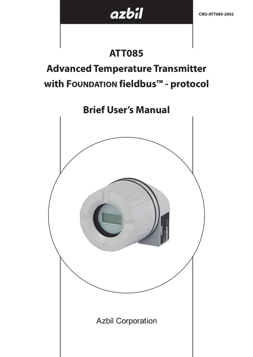
Azbil ATT085 User manual

ATT085
Advanced Temperature transmitter
with Foundation eldbusTM - protocol
User's Manual
CM2-ATT085-2001

NOTICE
While the information in this manual is presented in good faith and
believed to be accurate, Azbil Corporation disclaims any implied
warranty of merchantability or fitness for a particular purpose and
makes no express warranty except as may be stated in its written
agreement with and for its customer.
In no event shall Azbil Corporation be liable to anyone for any indirect,
special or consequential damages. is information and specications
in this document are subject to change without notice.
© 2015 Azbil Corporation All Rights Reserved.

Safety
Precautions for Use
For safe use of the product, the following symbols are used in this manual.
WARNING Warnings are indicated when mishandling the product might
result in the death or serious injury of the user.
CAUTION Cautions are indicated when mishandling the product might
result in minor injury to the user or damage to property.
■In describing the product, this manual uses the icons and conventions listed below.
Use caution when handling the product.
The indicated action is prohibited.
Be sure to follow the indicated instructions.
Handling Precautions:
Handling Precautions indicate items that the user should pay attention to when handling
the ATT.
To use this product correctly and safely, always observe the following precautions.
We are not responsible for damage or injury caused by the use of the product in violation of these precautions.
Handling Precautions for This Product
Installation Precautions
WARNING
When installing, use proper fittings and proper tightening torque for connections to the
process and to the exhaust. Gas leakage is dangerous because process gas and calibration
gas are flammable. Please refer to the leak check instructions in this manual and verify
that there is no gas leakage.
Do not use the product except at the rated pressure, specified connection standards, and
rated temperature. Use under other circumstances might cause damage that leads to a
serious accident.
For wiring work in an explosion-proof area, follow the work method stated in the
explosion-proof policy.
i

ii
CAUTION
After installation, do not step or stand on this unit. Doing so may damage the device or
cause injury.
Bumping the glass of the display with a tool may cause damage or injury. Be careful.
Install the device correctly. Incorrect or incomplete installation will cause output errors
and violation of regulations.
This product is quite heavy. Protect your feet with safety shoes when working.
Do not subject the product to shock or impact.
Wiring Precautions
WARNING
Do not do wiring work with wet hands or while electricity is being supplied to the product.
There is a danger of electric shock. When working, keep hands dry or wear gloves, and
turn off the power.
CAUTION
When wiring, check the specifications carefully and make sure to wire correctly. Incorrect
wiring can cause device damage or malfunction.
Supply electric power correctly according to the specifications. Supplying power that
differs from the specifications can damage the device.
Use a DC power supply that has overload protection.
Maintenance Precautions
WARNING
When removing this device for maintenance, be careful of residual pressure or residual
process gas. Leakage of process gas is dangerous.
When working on the vent, check its direction so that people do not come into contact
with vented gas. There is a danger of burns or other physical harm.
When the device is being used in an explosion-proof area, do not open the cover.
Opening the cover may cause an explosion.
CAUTION
This product was kept under carefully controlled conditions until it was shipped. Never try
to modify this device. Doing so could damage it.

iii
Table of Contents
Chapter 1. Identification . . . . . . . . . . . . . . . . . . . . . . . . . . . . . . . . . . . . . . . . . . . . . . . . . . . . . . . . . .1
1-1. Device designation . . . . . . . . . . . . . . . . . . . . . . . . . . . . . . . . . . . . . . . . . . . . . . . . . . . . . . . . . . . . . . . . . . . . . 1
1-1-1. Nameplate . . . . . . . . . . . . . . . . . . . . . . . . . . . . . . . . . . . . . . . . . . . . . . . . . . . . . . . . . . . . . . . . . . . . . . 1
1-2. Scope of delivery . . . . . . . . . . . . . . . . . . . . . . . . . . . . . . . . . . . . . . . . . . . . . . . . . . . . . . . . . . . . . . . . . . . . . . . 1
1-3. Certificates and approvals . . . . . . . . . . . . . . . . . . . . . . . . . . . . . . . . . . . . . . . . . . . . . . . . . . . . . . . . . . . . . . 1
1-3-1. CE mark, declaration of conformity . . . . . . . . . . . . . . . . . . . . . . . . . . . . . . . . . . . . . . . . . . . . . . . 1
1-3-2. Certification Foundation Fieldbus™ . . . . . . . . . . . . . . . . . . . . . . . . . . . . . . . . . . . . . . . . . . . . . . 2
1-4. Registered trademarks . . . . . . . . . . . . . . . . . . . . . . . . . . . . . . . . . . . . . . . . . . . . . . . . . . . . . . . . . . . . . . . . . 2
Chapter 2. Installation instructions . . . . . . . . . . . . . . . . . . . . . . . . . . . . . . . . . . . . . . . . . . . . . . . .3
2-1. Incoming acceptance, transport, storage . . . . . . . . . . . . . . . . . . . . . . . . . . . . . . . . . . . . . . . . . . . . . . . . 3
2-1-1. Incoming acceptance . . . . . . . . . . . . . . . . . . . . . . . . . . . . . . . . . . . . . . . . . . . . . . . . . . . . . . . . . . . 3
2-1-2. Transport and storage . . . . . . . . . . . . . . . . . . . . . . . . . . . . . . . . . . . . . . . . . . . . . . . . . . . . . . . . . . . 3
2-2. Installation conditions . . . . . . . . . . . . . . . . . . . . . . . . . . . . . . . . . . . . . . . . . . . . . . . . . . . . . . . . . . . . . . . . . . 3
2-2-1. Dimensions . . . . . . . . . . . . . . . . . . . . . . . . . . . . . . . . . . . . . . . . . . . . . . . . . . . . . . . . . . . . . . . . . . . . . 3
2-2-2. Installation point . . . . . . . . . . . . . . . . . . . . . . . . . . . . . . . . . . . . . . . . . . . . . . . . . . . . . . . . . . . . . . . . 3
2-3. Installation instructions . . . . . . . . . . . . . . . . . . . . . . . . . . . . . . . . . . . . . . . . . . . . . . . . . . . . . . . . . . . . . . . . 3
2-3-1. Mounting typical of Europe . . . . . . . . . . . . . . . . . . . . . . . . . . . . . . . . . . . . . . . . . . . . . . . . . . . . . . 4
2-3-2. Mounting the display . . . . . . . . . . . . . . . . . . . . . . . . . . . . . . . . . . . . . . . . . . . . . . . . . . . . . . . . . . . . 4
2-4. Post-installation check . . . . . . . . . . . . . . . . . . . . . . . . . . . . . . . . . . . . . . . . . . . . . . . . . . . . . . . . . . . . . . . . . . 5
Chapter 3. Wiring . . . . . . . . . . . . . . . . . . . . . . . . . . . . . . . . . . . . . . . . . . . . . . . . . . . . . . . . . . . . . . . . .7
3-1. Quick wiring guide . . . . . . . . . . . . . . . . . . . . . . . . . . . . . . . . . . . . . . . . . . . . . . . . . . . . . . . . . . . . . . . . . . . . . 7
3-2. Connecting the sensor cables . . . . . . . . . . . . . . . . . . . . . . . . . . . . . . . . . . . . . . . . . . . . . . . . . . . . . . . . . . 8
3-3. Foundation Fieldbus™ cable specification . . . . . . . . . . . . . . . . . . . . . . . . . . . . . . . . . . . . . . . . . . . . . . . . 9
3-3-1. Cable type . . . . . . . . . . . . . . . . . . . . . . . . . . . . . . . . . . . . . . . . . . . . . . . . . . . . . . . . . . . . . . . . . . . . . . 9
3-3-2. Maximum overall cable length . . . . . . . . . . . . . . . . . . . . . . . . . . . . . . . . . . . . . . . . . . . . . . . . . .10
3-3-3. Maximum spur length . . . . . . . . . . . . . . . . . . . . . . . . . . . . . . . . . . . . . . . . . . . . . . . . . . . . . . . . . .10
3-3-4. Number of field devices . . . . . . . . . . . . . . . . . . . . . . . . . . . . . . . . . . . . . . . . . . . . . . . . . . . . . . . .10
3-3-5. Shielding and grounding . . . . . . . . . . . . . . . . . . . . . . . . . . . . . . . . . . . . . . . . . . . . . . . . . . . . . . .10
3-3-6. Bus termination . . . . . . . . . . . . . . . . . . . . . . . . . . . . . . . . . . . . . . . . . . . . . . . . . . . . . . . . . . . . . . . .11
3-3-7. Further information . . . . . . . . . . . . . . . . . . . . . . . . . . . . . . . . . . . . . . . . . . . . . . . . . . . . . . . . . . . .11
3-4. Connecting the measuring unit . . . . . . . . . . . . . . . . . . . . . . . . . . . . . . . . . . . . . . . . . . . . . . . . . . . . . . . .12
3-4-1. Cable glands or entries . . . . . . . . . . . . . . . . . . . . . . . . . . . . . . . . . . . . . . . . . . . . . . . . . . . . . . . . . 12
3-4-2. Fieldbus connector . . . . . . . . . . . . . . . . . . . . . . . . . . . . . . . . . . . . . . . . . . . . . . . . . . . . . . . . . . . . .13
3-5. Post-connection check . . . . . . . . . . . . . . . . . . . . . . . . . . . . . . . . . . . . . . . . . . . . . . . . . . . . . . . . . . . . . . . .15
Chapter 4. Operation . . . . . . . . . . . . . . . . . . . . . . . . . . . . . . . . . . . . . . . . . . . . . . . . . . . . . . . . . . . 17
4-1. Quick operation guide . . . . . . . . . . . . . . . . . . . . . . . . . . . . . . . . . . . . . . . . . . . . . . . . . . . . . . . . . . . . . . . .17
4-2. Display and operating elements . . . . . . . . . . . . . . . . . . . . . . . . . . . . . . . . . . . . . . . . . . . . . . . . . . . . . . .18
4-2-1. Display . . . . . . . . . . . . . . . . . . . . . . . . . . . . . . . . . . . . . . . . . . . . . . . . . . . . . . . . . . . . . . . . . . . . . . . . .18
4-2-2. Display symbols . . . . . . . . . . . . . . . . . . . . . . . . . . . . . . . . . . . . . . . . . . . . . . . . . . . . . . . . . . . . . . . . 18
4-2-3. Local operation . . . . . . . . . . . . . . . . . . . . . . . . . . . . . . . . . . . . . . . . . . . . . . . . . . . . . . . . . . . . . . . .18
4-3. Foundation Fieldbus™ technology . . . . . . . . . . . . . . . . . . . . . . . . . . . . . . . . . . . . . . . . . . . . . . . . . . . . . .19
4-3-1. System architecture . . . . . . . . . . . . . . . . . . . . . . . . . . . . . . . . . . . . . . . . . . . . . . . . . . . . . . . . . . . .19
4-3-2. Link Active Scheduler (LAS) . . . . . . . . . . . . . . . . . . . . . . . . . . . . . . . . . . . . . . . . . . . . . . . . . . . . . 20
4-3-3. Data transfer . . . . . . . . . . . . . . . . . . . . . . . . . . . . . . . . . . . . . . . . . . . . . . . . . . . . . . . . . . . . . . . . . . .21
4-3-4. Device ID, addressing . . . . . . . . . . . . . . . . . . . . . . . . . . . . . . . . . . . . . . . . . . . . . . . . . . . . . . . . . . .21
4-3-5. Function blocks . . . . . . . . . . . . . . . . . . . . . . . . . . . . . . . . . . . . . . . . . . . . . . . . . . . . . . . . . . . . . . . . 21

iv
4-3-6. Fieldbus based process control . . . . . . . . . . . . . . . . . . . . . . . . . . . . . . . . . . . . . . . . . . . . . . . . .21
4-3-7. Device description . . . . . . . . . . . . . . . . . . . . . . . . . . . . . . . . . . . . . . . . . . . . . . . . . . . . . . . . . . . . .21
4-4. Configuration of the transmitter and FF functions . . . . . . . . . . . . . . . . . . . . . . . . . . . . . . . . . . . . . .22
4-5. Hardware settings (optional) . . . . . . . . . . . . . . . . . . . . . . . . . . . . . . . . . . . . . . . . . . . . . . . . . . . . . . . . . .22
Chapter 5. Commissioning . . . . . . . . . . . . . . . . . . . . . . . . . . . . . . . . . . . . . . . . . . . . . . . . . . . . . . 25
5-1. Function check . . . . . . . . . . . . . . . . . . . . . . . . . . . . . . . . . . . . . . . . . . . . . . . . . . . . . . . . . . . . . . . . . . . . . . . .25
5-2. Switching on the measuring device . . . . . . . . . . . . . . . . . . . . . . . . . . . . . . . . . . . . . . . . . . . . . . . . . . . .25
5-3. Commissioning . . . . . . . . . . . . . . . . . . . . . . . . . . . . . . . . . . . . . . . . . . . . . . . . . . . . . . . . . . . . . . . . . . . . . . .26
5-3-1. Initial commissioning . . . . . . . . . . . . . . . . . . . . . . . . . . . . . . . . . . . . . . . . . . . . . . . . . . . . . . . . . . . 27
Chapter 6. Maintenance . . . . . . . . . . . . . . . . . . . . . . . . . . . . . . . . . . . . . . . . . . . . . . . . . . . . . . . . 33
Chapter 7. Troubleshooting . . . . . . . . . . . . . . . . . . . . . . . . . . . . . . . . . . . . . . . . . . . . . . . . . . . . . 35
7-1. Troubleshooting instructions . . . . . . . . . . . . . . . . . . . . . . . . . . . . . . . . . . . . . . . . . . . . . . . . . . . . . . . . . .35
7-2. Status messages . . . . . . . . . . . . . . . . . . . . . . . . . . . . . . . . . . . . . . . . . . . . . . . . . . . . . . . . . . . . . . . . . . . . . .38
7-2-1. Corrosion monitoring . . . . . . . . . . . . . . . . . . . . . . . . . . . . . . . . . . . . . . . . . . . . . . . . . . . . . . . . . .43
7-3. Application errors without messages . . . . . . . . . . . . . . . . . . . . . . . . . . . . . . . . . . . . . . . . . . . . . . . . . . 44
7-3-1. Application errors for RTD connection . . . . . . . . . . . . . . . . . . . . . . . . . . . . . . . . . . . . . . . . . . .44
7-3-2. Application errors for TC connection . . . . . . . . . . . . . . . . . . . . . . . . . . . . . . . . . . . . . . . . . . . . 45
7-4. Spare parts . . . . . . . . . . . . . . . . . . . . . . . . . . . . . . . . . . . . . . . . . . . . . . . . . . . . . . . . . . . . . . . . . . . . . . . . . . .46
7-5. Return . . . . . . . . . . . . . . . . . . . . . . . . . . . . . . . . . . . . . . . . . . . . . . . . . . . . . . . . . . . . . . . . . . . . . . . . . . . . . . . .46
7-6. Disposal . . . . . . . . . . . . . . . . . . . . . . . . . . . . . . . . . . . . . . . . . . . . . . . . . . . . . . . . . . . . . . . . . . . . . . . . . . . . . . 46
7-7. Software history and overview of compatibility . . . . . . . . . . . . . . . . . . . . . . . . . . . . . . . . . . . . . . . .46
Chapter 8. Technical Data . . . . . . . . . . . . . . . . . . . . . . . . . . . . . . . . . . . . . . . . . . . . . . . . . . . . . . 47
8-1. Input . . . . . . . . . . . . . . . . . . . . . . . . . . . . . . . . . . . . . . . . . . . . . . . . . . . . . . . . . . . . . . . . . . . . . . . . . . . . . . . .47
8-2. Output . . . . . . . . . . . . . . . . . . . . . . . . . . . . . . . . . . . . . . . . . . . . . . . . . . . . . . . . . . . . . . . . . . . . . . . . . . . . . . .48
8-3. Power supply . . . . . . . . . . . . . . . . . . . . . . . . . . . . . . . . . . . . . . . . . . . . . . . . . . . . . . . . . . . . . . . . . . . . . . . . . 48
8-4. Performance characteristics. . . . . . . . . . . . . . . . . . . . . . . . . . . . . . . . . . . . . . . . . . . . . . . . . . . . . . . . . . . .48
8-5. Environment . . . . . . . . . . . . . . . . . . . . . . . . . . . . . . . . . . . . . . . . . . . . . . . . . . . . . . . . . . . . . . . . . . . . . . . . . 52
8-6. Mechanical construction . . . . . . . . . . . . . . . . . . . . . . . . . . . . . . . . . . . . . . . . . . . . . . . . . . . . . . . . . . . . . . 53
8-7. Certificates and approvals . . . . . . . . . . . . . . . . . . . . . . . . . . . . . . . . . . . . . . . . . . . . . . . . . . . . . . . . . . . . .54
Chapter 9. Operation via Foundation Fieldbus™ . . . . . . . . . . . . . . . . . . . . . . . . . . . . . . . . . . . 55
9-1. Block model . . . . . . . . . . . . . . . . . . . . . . . . . . . . . . . . . . . . . . . . . . . . . . . . . . . . . . . . . . . . . . . . . . . . . . . . . .55
9-2. Resource Block (device block) . . . . . . . . . . . . . . . . . . . . . . . . . . . . . . . . . . . . . . . . . . . . . . . . . . . . . . . . .56
9-2-1. Selecting the operating mode . . . . . . . . . . . . . . . . . . . . . . . . . . . . . . . . . . . . . . . . . . . . . . . . . .56
9-2-2. Block status . . . . . . . . . . . . . . . . . . . . . . . . . . . . . . . . . . . . . . . . . . . . . . . . . . . . . . . . . . . . . . . . . . . . 56
9-2-3. Write protection and simulation . . . . . . . . . . . . . . . . . . . . . . . . . . . . . . . . . . . . . . . . . . . . . . . .57
9-2-4. Alarm detection and processing . . . . . . . . . . . . . . . . . . . . . . . . . . . . . . . . . . . . . . . . . . . . . . . .57
9-2-5. Resource Block FF parameters . . . . . . . . . . . . . . . . . . . . . . . . . . . . . . . . . . . . . . . . . . . . . . . . . .58
9-3. Transducer Blocks . . . . . . . . . . . . . . . . . . . . . . . . . . . . . . . . . . . . . . . . . . . . . . . . . . . . . . . . . . . . . . . . . . . . .64
9-3-1. Block output variables . . . . . . . . . . . . . . . . . . . . . . . . . . . . . . . . . . . . . . . . . . . . . . . . . . . . . . . . . .64
9-3-2. Selecting the operating mode . . . . . . . . . . . . . . . . . . . . . . . . . . . . . . . . . . . . . . . . . . . . . . . . . .65
9-3-3. Alarm detection and processing . . . . . . . . . . . . . . . . . . . . . . . . . . . . . . . . . . . . . . . . . . . . . . . .65
9-3-4. Accessing the manufacturer-specific parameters . . . . . . . . . . . . . . . . . . . . . . . . . . . . . . . .65
9-3-5. Selecting the units . . . . . . . . . . . . . . . . . . . . . . . . . . . . . . . . . . . . . . . . . . . . . . . . . . . . . . . . . . . . . .65
9-3-6. Transducer Block FF parameters . . . . . . . . . . . . . . . . . . . . . . . . . . . . . . . . . . . . . . . . . . . . . . . .65
9-3-7. Transducer Blocks “Sensor 1 and 2” . . . . . . . . . . . . . . . . . . . . . . . . . . . . . . . . . . . . . . . . . . . . .69
9-3-8. Transducer Block “Advanced Diagnostic” . . . . . . . . . . . . . . . . . . . . . . . . . . . . . . . . . . . . . . . .78
9-3-9. Transducer Block “Display” . . . . . . . . . . . . . . . . . . . . . . . . . . . . . . . . . . . . . . . . . . . . . . . . . . . . . .82

v
9-4. Analog Input function block . . . . . . . . . . . . . . . . . . . . . . . . . . . . . . . . . . . . . . . . . . . . . . . . . . . . . . . . . . .84
9-5. PID function block (PID controller) . . . . . . . . . . . . . . . . . . . . . . . . . . . . . . . . . . . . . . . . . . . . . . . . . . . . . 84
9-6. Input Selector function block . . . . . . . . . . . . . . . . . . . . . . . . . . . . . . . . . . . . . . . . . . . . . . . . . . . . . . . . . .84

vi

1
Chapter 1. Identification
1-1. Device designation
1-1-1. Nameplate
The right device?
Compare the nameplate on the device with the following graphic:
ATT85-xxxxx
Fig 1-1. Nameplate of the head transmitter (example, non-Ex version)
1 Approval information (optional)
2 Serial number
3 Device revision
4 Power supply and current consumption
5 Device identification number and communication symbol
1-2. Scope of delivery
The scope of delivery of the device comprises:
Temperature transmitter
Securing material
User's Manual
Additional documentation for devices that are suitable for use in hazardous areas, such as
Safety Instructions, Control or Installation Drawings.
1-3. Certificates and approvals
The device is designed in accordance with good engineering practice to meet state-of-the-
art safety requirements, has been tested and left the factory in a condition in which it is safe
to operate. The device complies with the standards EN 61 010-1 “Protection Measures for
Electrical Equipment for Measurement, Control, Regulation and Laboratory Procedures” and
with the EMC requirements of IEC/EN 61326.
1-3-1. CE mark, declaration of conformity
The device described in these User's Manual is therefore in conformity with the statutory
requirements of the EU Directives. The manufacturer confirms a positive completion of all
tests by fitting the unit with a CE mark.

2
1-3-2. Certification Foundation Fieldbus™
The temperature transmitter has successfully passed all the tests and is certified and
registered by the Fieldbus Foundation. The device meets all the requirements of the following
specifications:
Certified in accordance with F Fieldbus™ specification
F Fieldbus™ H1
Interoperability Test Kit (ITK), revision status 6.0.1 (device certification number
available on request): the device may also be operated using certified devices from other
manufacturers
Physical Layer Conformance Test of the Fieldbus F™ (FF-830 FS 1.0)
An overview of additional approvals and certifications can be found on page 49.
1-4. Registered trademarks
F FieldbusTM
Registered trademark of the Fieldbus Foundation Austin, Texas, USA

3
Chapter 2. Installation instructions
2-1. Incoming acceptance, transport, storage
2-1-1. Incoming acceptance
On receipt of the goods, check the following points:
Are the contents or the packaging damaged?
Is the delivery complete and is anything missing? Check the scope of delivery against you
order.
2-1-2. Transport and storage
Note the following points:
Pack the device in such a way as to protect it reliably against impact for storage (and
transportation). The original packaging provides optimum protection.
The permitted storage temperature is -40 to +100 °C (-40 to 212 °F).
2-2. Installation conditions
2-2-1. Dimensions
The dimensions of the device can be found in chapter 10 ''Technical data''.
2-2-2. Installation point
In the terminal head, flat face, as per DIN 43729, direct mounting on insert with cable
entry (middle hole 7 mm)
In the field housing, separate from the process (see Section 8 'Accessories')
Information on installation conditions, such as ambient temperature, protection classification,
climatic class etc., can be found in chapter 10 “Technical data”.
When using in the hazardous area, the limit values of the certificates and approvals must be
observed (see Safety Instructions).
2-3. Installation instructions
A screwdriver is needed to mount the head transmitter.
Handling Precautions:
Damage of the head transmitter
Do not overtighten the mounting screws as this could damage the head
transmitter. Maximum torque = 1 Nm (. pound-feet).

4
2-3-1. Mounting typical of Europe
Fig 2-1. Head transmitter mounting (three versions)
Mounting in a field housing
1 Field housing cover
2 Mounting screws with springs
3 Head transmitter
4 Field housing
Procedure:
1. Open the cover (1) of the field housing (4).
2. Guide the mounting screws (2) through the lateral bores of the head transmitter (3).
3. Screw the head transmitter to the field housing.
4. When wiring is complete (see section 4), screw the field housing cover (1) back on.
2-3-2. Mounting the display
1.Open the terminal head cap (1).
2.Remove the cover of the display connection (2). Plug the display module onto the mounted and
wired head transmitter. The mounting pins (3) must snap securely into the head transmitter.
3.After mounting the display, close the terminal head cap and refit the screw.

5
Fig 2-2. Mounting the display
The display can only used with suitable terminal heads with display window.
2-4. Post-installation check
After installing the device, always run the following final checks:
Device condition and specifications Notes
Is the device visibly damaged (visual check)? -
Does the device comply to the measurement point specifications, such
as ambient temperature, measurement range etc.?
S e e c h a p t e r
8 “Technical
Data”
Handling Precautions:
Make sure the sensor type.
Make sure that the sensor type and model are correct.
Use of the incorrect sensor and model might cause temperature errors or
abnormal outputs.

6

7
Chapter 3. Wiring
CAUTION
Switch off power supply before installing or connecting the device. Failure to observe this
may result in destruction of parts of the electronics.
When installing Ex-approved devices in a hazardous area please take special note of the
instructions and connection schematics in the respective Ex documentation added to
these Operating Instructions. Your supplier is available for assistance if required.
Do not occupy the display connection. An incorrect connection can destroy the
electronics.
A Phillips head screwdriver is required to wire the head transmitter with screw terminals. A
flat-bladed screwdriver must be used for the version with spring terminals.
Handling Precautions:
fDo not overtighten the screw terminals, as this could damage the
transmitter.
fMaximum torque = 1 Nm (¾ pound-feet).
For wiring a mounted head transmitter, proceed as follows:
1. Open the cable gland and the housing cover on the terminal head or the field housing.
2. Feed the cables through the opening in the cable gland.
3. Connect the cables as shown in Fig. 3-1. If the head transmitter is fitted with spring terminals.
4. Retighten the cable gland and close the housing cover.
5. In order to avoid connection errors always take note of the hints given in the section connection
check!
3-1. Quick wiring guide
-
+
+
1
-
2
7
6
5
4
3
1
2
7
6
5
4
3
Sensor input 2 Sensor input 1 Bus connection
and supply voltage
Display connection
TC, mV
RTD,Ω:4-, 3- and 2-wire
RTD,Ω: 3-and 2-wire
TC, mV
white
red
red
white
white
red
red
Fig. 3-1. Wiring the head transmitter
Handling Precautions:
ESD - electrostatic discharge. Protect the terminals from electrostatic discharge.
Failure to observe this may result in destruction or malfunction of parts of the
electronics.

8
3-2. Connecting the sensor cables
Handling Precautions:
When connecting 2 sensors ensure that there is no galvanic connection
between the sensors (e.g. caused by sensor elements that are not isolated from
the thermowell). The resulting equalizing currents distort the measurements
considerably. In this situation, the sensors have to be galvanically isolated from one
another by connecting each sensor separately to a transmitter. The device provides
sufficient galvanic isolation (> 2 kV AC) between the input and output.
Please refer to Fig. 3-1 for the terminal assignment of the sensor connections.
The following connection combinations are possible when both sensor inputs are assigned:
Sensor input 1
Sensor
input 2
RTD or
resistance
transmitter,
2- wire
RTD or
resistance
transmitter,
3- wire
RTD or
resistance
transmitter,
4- wire
Thermocouple
(TC), voltage
transmitter
RTD or
resistance
transmitter,
2-wire
-
RTD or
resistance
transmitter,
3-wire
-
RTD or
resistance
transmitter,
4-wire
----
Thermocouple
(TC), voltage
transmitter

9
3-3. Foundation Fieldbus™ cable specification
3-3-1. Cable type
Twin-core cables are required for connecting the device to the F Fieldbus™ H1.
Following IEC 61158-2 (MBP), four different cable types (A, B, C, D) can be used with the
F Fieldbus™, only two of which (cable types A and B) are shielded.
Cable types A or B are particularly preferable for new installations. Only these types have
cable shielding that guarantees adequate protection from electromagnetic interference and
thus the most reliable data transfer. In the case of cable type B, several field buses (same
degree of protection) may be operated in one cable. No other circuits are permissible in the
same cable.
Practical experience has shown that cable types C and D should not be used due to the lack
of shielding, since the freedom from interference generally does not meet the requirements
described in the standard.
The electrical data of the fieldbus cable have not been specified but determine important
characteristics of the design of the fieldbus, such as distances bridged, number of users,
electromagnetic compatibility, etc.
Type A Type B
Cable structure Twisted pair, shielded One or more twisted
pairs, fully shielded
Wire size 0.8 mm2(AWG 18) 0.32 mm2(AWG 22)
Loop-resistance (direct current) 44 /km 112 /km
Characteristic impedance at 31.25 kHz 100 ± 20% 100 ± 30%
Attenuation constant at 39 kHz 3 dB/km 5 dB/km
Capacitive asymmetry 2 nF/km 2 nF/km
Envelope delay distortion (7.9 to 39
kHz) 1.7 ms/km *
Shield coverage 90% *
Max. cable length (incl. spurs >1 m) 1900 m (6233 ft) 1200 m (3937 ft)
* Not specified
Suitable fieldbus cables (type A) from various manufacturers for non-hazardous areas are
listed below:
Siemens: 6XV1 830-5BH10
Belden: 3076F
Kerpen: CeL-PE/OSCR/PVC/FRLA FB-02YS(ST)YFL

10
3-3-2. Maximum overall cable length
The maximum network expansion depends on the type of protection and the cable
specifications. The overall cable length combines the length of the main cable and the length
of all spurs (>1 m/3.28 ft). Note the following points:
The maximum permissible overall cable length depends on the cable type used.
If repeaters are used, the maximum permissible cable length is doubled. A maximum of
three repeaters are permitted between user and master.
3-3-3. Maximum spur length
The line between the distribution box and field device is described as a spur.
In the case of non-Ex applications, the max. length of a spur depends on the number of spurs
(>1m/3.28 ft):
Number of spurs 1 to 12 13 to 14 15 to 18 19 to 24 25 to 32
Max. length per spur 120 m (393 ft) 90 m (295 ft) 60 m (196 ft) 30 m (98 ft) 1 m (3.28 ft)
3-3-4. Number of field devices
In accordance with IEC 61158-2 (MBP), a maximum of 32 field devices can be connected
per fieldbus segment. However, this number is restricted under certain conditions (explosion
protection, bus power option, field device current consumption). A maximum of four field
devices can be connected to a spur.
3-3-5. Shielding and grounding
Optimum electromagnetic compatibility (EMC) of the fieldbus system can only be guaranteed
if the system components and, in particular, the lines are shielded and the shield forms as
complete a cover as possible. A shield coverage of 90% is ideal.
To ensure an EMC protective effect, connect the shield as often as possible to the reference
ground.
For reasons of explosion protection, you should refrain from grounding however.
To comply with both requirements, the F Fieldbus™ basically allows three different
types of shielding:
Shielding at both ends
Shielding at one end on the feed side with capacitance connection to the field device
Shielding at one end on the feed side
Experience shows that the best results with regard to EMC are achieved in most cases in
installations with one-sided shielding. Appropriate measures with regard to input wiring must
be taken to allow unrestricted operation when EMC interference is present. These measures
have been taken into account for this device. Operation in the event of disturbance variables as
per NAMUR NE21 is possible with one-sided shielding.
Where applicable, national installation regulations and guidelines must be observed during
the installation!
Where there are large differences in potential between the individual grounding points, only
one point of the shielding is connected directly with the reference ground. In systems without
potential equalization, therefore, cable shielding of fieldbus systems should only be grounded
on one side, for example at the fieldbus supply unit or at safety barriers, Fig. 3-2.

11
Fig. 3-2. Shielding and one-sided grounding of the fieldbus cable shielding
1 Supply unit
2 Distribution box (T-box)
3 Bus terminator
4 Grounding point for fieldbus cable shielding
5 Optional grounding of the field device, isolated from cable shielding.
Handling Precautions:
If the shielding of the cable is grounded at more than one point in systems without
potential matching, power supply frequency equalizing currents can occur that
damage the bus cable or shielding or have serious effect on signal transmission.
fIn such cases the shielding of the fieldbus cable is to be grounded on only
one side, i.e. it must not be connected to the ground terminal of the housing
(terminal head, field housing). The shield that is not connected should be
insulated!
3-3-6. Bus termination
The start and end of each fieldbus segment are always to be terminated with a bus terminator.
With various junction boxes (non-Ex), the bus termination can be activated via a switch. If
this is not the case, a separate bus terminator must be installed. Note the following points in
addition:
In the case of a branched bus segment, the device furthest from the segment coupler
represents the end of the bus.
If the fieldbus is extended with a repeater, then the extension must also be terminated at
both ends.
3-3-7. Further information
General information and further pointers on wiring can be found on www.fieldbus.org, the
Web site of the Fieldbus Foundation.

12
3-4. Connecting the measuring unit
Devices can be connected to the F Fieldbus™ in two ways:
Connection via conventional cable gland →Chapter 3-4-1
Connection via fieldbus connector (optional, can be purchased as an accessory) →Chapter
3-4-2
Handling Precautions:
Risk of damaging
fSwitch off power supply before installing or connecting the head transmitter.
Failure to observe this may result in destruction of parts of the electronics.
fGrounding via one of the grounding screws (terminal head, field housing) is
recommended.
fIf the shielding of the fieldbus cable is grounded at more than one point in
systems without additional potential matching, power supply frequency
equalizing currents can occur that damage the cable or the shielding. In such
cases the shielding of the fieldbus cable is to be grounded on only one side,
i.e. it must not be connected to the ground terminal of the housing (terminal
head, field housing). The shield that is not connected should be insulated!
fWe recommend that the fieldbus not be looped using conventional
cable glands. If you later replace even just one measuring device, the bus
communication will have to be interrupted.
3-4-1. Cable glands or entries
Please also observe the general procedure on page 6.
Fig. 3-3. Connection to the Foundation Fieldbus™ fieldbus cable - installed
in the field housing on the left, and in the terminal head on the right
A FF terminals - fieldbus communication and power supply
B Inner ground terminal
C Outer ground terminal
D Shielded fieldbus cable (F Fieldbus™)
Other manuals for ATT085
1
Table of contents
Other Azbil Transmitter manuals

Azbil
Azbil ATT082 Instructions for use

Azbil
Azbil SLX 110 User manual

Azbil
Azbil MagneW Plus+ MGG14C User manual

Azbil
Azbil ALTJ 9000 Series User manual

Azbil
Azbil JTD720A User manual

Azbil
Azbil ATT082 User manual

Azbil
Azbil PTG71 User manual

Azbil
Azbil ATT085 User manual

Azbil
Azbil JTD910S User manual

Azbil
Azbil PREX3000 User manual