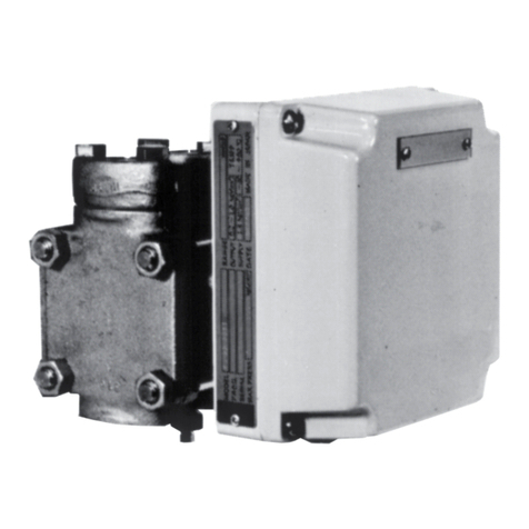
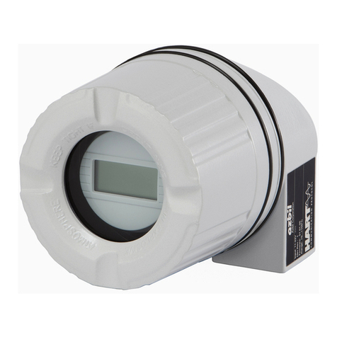
Azbil JTD910S User manual

AdvancedDifferential Pressure
and Pressure Transmitter
Model JTD/JTG/JTA/JTC/JTE/JTH/JTS
User's Manual
CM2-ATS100-2001

Introductory Notes and Requests
• Please ensure that this manual is in the possession of the individual in charge of using this
product.
• Reproduction or transmission of this manual, in whole or in part, is prohibited.
• The descriptions in this manual are subject to change without notice.
• It is our hope that this manual is complete and accurate, but in the event that there is
content which is incomplete or whose accuracy is in question, please contact us.
• Please understand that we cannot in some cases accept responsibility for the results of use
of this equipment by the customer.
• This product was designed, developed, and manufactured under the assumption that
it would be used as a general-purpose model and as an explosion-proof model. Do not
use this product for applications in which its operation directly affects human life, or for
nuclear energy applications in radiation controlled areas.
For applications such as
safety devices whose purpose is to protect people
direct control of transportation equipment
aircraft
spacecraft
and the like, where safety is a necessity, be sure to use this product in a context in which
the overall safety of the systems and equipment is taken into consideration using, for
example, fail-safe design, redundant design, and periodic inspection. For information
regarding system design, application design, usage methods, product applications, etc.,
consult with the relevant personnel at our company. Please understand that we cannot in
some cases accept responsibility for the results of use of this equipment by the customer.
• HART® is a registered trademark of FieldComm Group.
©2014-2022 Azbil Corporation. All Rights Reserved.

i
Introduction
Introduction
Thank you for purchasing an Azbil advanced transmitter series.
Structure of this Series
This series has the following models and model number configuration.
Differential
Pressure
Transmitters
Gauge Pressure
Transmitters
Absolute
Gauge Pressure
Transmitters
Flange Type
Differential
Pressure
Transmitters
JTD910S
JTD920S
JTD930S
JTD921S
JTD931S
JTD960S
JTD961S
JTG940S
JTG960S
JTG980S
JTA922S
JTA940S
JTC929S
JTC940S
Remote Seal Type
Differential Pressure
Transmitters
Remote Seal Type
Gauge Pressure
Transmitters
Remote Seal Type
Absolute Pressure
Transmitters
JTE929S
JTE930S
JTH920S
JTH940S
JTH960S
JTS922S
JTS940S
Note: If an external terminal box is attached, the model type will end in "W" rather than "S."

ii
Introduction
Usage Precautions
Introduction
In order to use this product safely, it is essential to install and operate it correctly, and
to carry out periodic maintenance. Please read and understand the safety precautions
described in this operation manual carefully before carrying out installation, operation,
and maintenance.
Checks
• When you first receive the product, please confirm that there are no errors in the
specifications, and that no damage occurred during transport. This product was
shipped only after being tested under a rigorous quality control program. In the
unlikely event that there are problems regarding quality or specifications, please notify
us of the model number and production number appearing on the nameplate.
• The nameplate is affixed on the upper portion of the case.
Safety Precautions
In order to promote safe use of the product, this operation manual uses the following
symbols.
Warning Cautionary notes aimed at preventing dangerous
situations when it is anticipated that such dangerous
situations, in which the product user could be
seriously or fatally harmed as a result of product
misuse, might arise.
Caution Cautionary notes aimed at preventing dangerous
situations when it is anticipated that such dangerous
situations, in which the product user could sustain
minor injuries or physical damage could occur as a
result of product misuse, might arise.
In order to use the product safely, be sure to follow the cautionary notes on the next page.
We cannot warrant or take responsibility for damage resulting from handling of the
product in violation of these cautionary notes.
Examples of visual indicators
This indicates an action that is prohibited.
This indicates an instruction that the user should be sure to follow.

iii
Introduction
Product Usage Precautions
Usage Limitations and Requests
This product was designed, developed, and manufactured under the assumption that it would be used
asageneral-purpose model and as an explosion-proof model. Do not use this product for applications in which
its operation directly affects human life, or for nuclear energy applications in radiation controlled areas.
For applications such as
safety equipment whose purpose is to protect people
direct control of transportation equipment
aircraft
spacecraft
and the like, where safety is a necessity, be sure to use this product in a context in which the overall safety of the
systems and equipment is taken into consideration using, for example, fail-safe design, redundant design, and
periodic inspection.
For information regarding system design, application design, usage methods, product applications, etc.,
consult with the relevant personnel at our company. Please understand that we cannot in some cases accept
responsibility for the results of use of this equipment by the customer.
Installation Precautions
Warning
Depending on the model, this product weighs over 10 kg. Be sufficiently careful when transporting or installing
this product, for example by using a transportation apparatus or by having two or more people carry the
product. Lifting and dropping the product without sufficient care can cause injuries or product damage.
When installing the product, make sure that the gaskets do not stick out at the connections with the process
(connections between adapter flanges and connecting pipes and flanges). Also be careful not to forget to
close vent and drain plugs. There is a danger that the measured fluid will leak out and cause scalding and
other harmful health effects. If the measured fluid is harmful to the human body, take safety measures such
as wearing goggles or a mask so that it does not adhere to the skin or the eyes, become inhaled, etc.
Use this product within the limits of the described usage conditions (explosion proofing, pressure rating,
temperature, humidity, voltage, vibration, shock, installation orientation, ambient atmosphere, and the like).
There is a danger of scalding and other harmful health effects as a result of instrument failure, fire, etc.
To ensure safety, have personnel with specific technical expertise in instrumentation work, electrical
work, etc., perform the installation, wiring, and the like. When working in a hazardous area, perform
installation and deployment according to the construction methods prescribed by the hazard guidelines.
Caution
After installing this product, do not use it as a scaffold, place your body weight on it, etc. This may cause
damage to the product. In addition, there is a danger of slipping and being injured.
Bringing tools and the like into contact with the glass portion of the display can cause damage or injury.
Ground the product properly in accordance with the instructions in this operation manual. If the product
is not properly grounded, the output may be affected. Also, improper grounding is contrary to the
explosion-proofing guidelines.
Do not subject this product to shock or impact, as they can cause product damage.
Use a power supply for this product which has overcurrent protection capability.

iv
Introduction
Wiring Precautions
Caution
Do not perform wiring work, turn on the electricity, etc., when your hands are wet. Also, do not perform
hot swapping. There is a risk of electric shock. Do this work with dry hands or wearing gloves, and with
the electricity turned off.
Be sure to thoroughly check the specifications to ensure that the wiring is carried out correctly. Incorrect
wiring can cause instrument damage or malfunctions.
Supply power correctly based on the specifications. Inputting an incorrect power supply can damage the
instrument, and the individual doing the work can become injured.
Maintenance Precautions
Warning
When detaching this product from the process for maintenance and the like, clear vents and drains in
order to remove residual pressure and residues in the measurement target. In addition, when clearing
vents and drains, check the direction in which material will come out in order to avoid any contact with
the human body. There is a danger of scalding and other harmful health effects. If the measured fluid is
harmful to the human body, take safety measures such as wearing goggles or a mask so that it does not
adhere to the skin or the eyes, become inhaled, etc.
When using the product in a hazardous area, do not open its case cover, electrical conduits, etc. There is
a risk of explosion, etc.
When using the product in a hazardous area, check that the threaded parts of connecting surfaces on the
case cover, electrical conduit connection port, etc., are not corroded, deformed, cracked, or otherwise
damaged. If its explosion-proofing performance is impaired, the product can become an ignition source,
and there is a risk of explosion. Perform periodic maintenance on this product, and replace it with a new
one if corrosion etc., reaches significant levels.
Replace damaged seal gaskets. If this product is operated in a damaged state, it will not be possible to
ensure sufficient performance of the seals, and there is a danger that the measured fluid will spurt out,
possibly resulting in scalding and other harmful health effects.
If evidence of corrosion is observed in pressure-bearing parts such as bolts, nuts, cover flanges, and
adapter flanges, replace them. Parts whose pressure-resistance has decreased can break and are thus
dangerous. There is also a risk of physical injuries such as bruises and lacerations.
Be sufficiently careful of residues from measured fluids which are left behind in the product. If materials
which affect the human body are contained in these residues, harmful effects on human health could
result. When performing maintenance on a product which has been uninstalled, first clean the pressure-
receiving parts adequately.
Caution
Do not disassemble or alter this product. Doing so may lead to product failure, electric shock, etc.
Explosion-proof instruments cannot be inspected or disassembled in hazardous areas. In addition,
explosion-proof products cannot be used after having been altered.
If this product is used with high-temperature fluids, do not carelessly touch the body of the product.
It will likely have become hot, so there is a risk of sustaining burns.
When this product is no longer to be used, dispose of it in accordance with local regulations, treating it as
industrial waste. Also, do not reuse this product in whole or in part.
v
Introduction
Communication Device Usage Precautions
If communication devices such as transceivers, cellular phones, PHS phones, or pagers are
used in the vicinity of this product, depending on the transmission frequencies being used
there may cases in which the product does not function properly, so please observe the
following precautions.
• Before using a communication device, check the distance at which the
communication device does not affect the operation of this product, and maintain
that distance or more when using the communication device.
• Close the case cover of the transmission unit before using communication devices.
HART Communication Usage Precautions
• If, as a result of burnout, the output of this device drops to 6 mA or 3.2 mA
(optional) or lower, HART communication may not be possible. In such cases, turn
the power off and then on again before starting communication. If burnout and
communication failure persist, there is a chance that the product is broken, so please
contact us.
Usage precautions for devices using HART
• If, as a result of the effects of electrical noise in the installation environment, HART
communication with the host is not possible, take countermeasures such as distancing
the signal cable from the noise sources, re-evaluating the grounding conditions,
and changing the signal cable to a shielded cable. Incidentally, even if HART
communication is not possible due to noise, the 4-20 mA analog signal will not be
affected.
• When using this product in multidrop mode, there is a limit to the number of units
which can be used. If using multidrop, please consult our representative for more
details.
Disposal precaution for Electrical and Electronic Equipment
Disposal of Electrical and Electronic Equipment (for Environmental Protection)
This is an industrial product subject to the WEEE Directive.
Do not dispose of electrical and electronic equipment in the same way as household waste.
Old products contain valuable raw materials and must be returned to an authorized
collection point for correct disposal or recycling.

vi
Introduction
Product unpacking, verification, and storage
Unpacking
This product is a precision instrument. Handle it carefully in order to prevent accidents,
injuries, etc.
Verifying accessories
Upon unpacking the product, verify that the main body and the following items have been
included.
• Standard accessory: M3 size L-wrench (1)
• Operation Manual (with CD)
Checking specifications
The specifications appear on the product's nameplate. Compare them to the expected
specifications. In particular, be sure to check the following specifications.
• Tag number (TAG No.)
• Model number (MODEL)
• Production number (PROD. No.)
• High and low limits of the setting range (RANGE)
• Supply voltage (SUPPLY)
• Explosion-proofing test conformity label (if explosion-proofing specification applies)
Note: The production number (PROD No.) is equivalent to the serial number specified in IEC
60079-0. A unique production number is assigned to each individual product.
Inquiries
Please direct inquiries regarding this product to the branch office or sales office of our
company which is closest to you.
When making an inquiry, be sure to let us know the following numbers appearing on the
nameplate.
• Model number (MODEL)
• Production number (PROD. No.)
Storage
If the product is to be placed in long-term storage immediately after purchase, please
observe the following precautions.
• Store the product indoors in a low-vibration, low-shock area which has stable
temperature and humidity.
• Store the product in the packed state in which it was delivered.

vii
Table of Contents
Table of Contents
Chapter 1
Functionality, Configuration, and Structure of this Device and CommStaff
..1-1
1-1 Functionality and Configuration of this Device.......................................1-1
1-1-1 Functionality and Configuration of this Device.................................1-1
1-1-2 Part Names. . . . . . . . . . . . . . . . . . . . . . . . . . . . . . . . . . . . . . . . . . . . . . . . . . . . . . . . . . . . . . . . 1-2
1-1-3 Indicators (Optional) .......................................................1-4
1-2 CommStaff Functionality and Configuration.........................................1-7
1-2-1 Introduction ..............................................................1-7
1-2-2 Precautions ...............................................................1-7
1-2-3 Configuration of CommStaff and Peripheral Devices............................1-7
1-2-4 Usage Environment ........................................................1-7
1-2-5 Conditions for Connected Devices ...........................................1-8
Chapter 2 Installation of this Device .......................................2-1
2-1 Installation Location Selection Criteria..............................................2-1
2-1-1 General Installation Conditions ..............................................2-1
2-1-2 Explosion-Proof Transmitter Installation Criteria...............................2-1
2-1-3 Equipment use conditions...................................................2-4
2-2 Installation ......................................................................2-5
2-2-1 Installation Dimensions.....................................................2-5
2-2-2 Installation Location .......................................................2-5
2-2-3 Transmitter Body Installation................................................2-5
2-2-4 Connecting the Wetted Part of a Flange Type or Remote Seal Type to the Process ...2-9
2-2-5 Precautions When Attaching FEP Protective Film .............................2-12
2-2-6 Fit-Tank Attachment (JTE Model)...........................................2-15
2-2-7 1/2B Remote Attachment (JTE/JTH Model) ..................................2-20
2-2-8 Installation of the Flushing Ring (Model DV)
to a Flanged Transmitter (Models JTE, JTH, JTS, and JTC). . . . . . . . . . . . . . . . . . . . . . 2-22
2-3 Piping ........................................................................2-26
2-3-1 Flow Rate Measurement Piping (JTD Model) .................................2-26
2-3-2 Pressure Measurement Piping (JTD/JTG/JTA Model) ..........................2-31
2-3-3 Liquid Level Measurement Piping (JTD/JTG Model)...........................2-34
2-3-4 Liquid Level Measurement Piping (JTC Model) ...............................2-39
2-4 Electrical Wiring ................................................................2-41
2-4-1 General Wiring ...........................................................2-41
2-4-2 Wiring for Explosion-Proof Models .........................................2-44
2-5 Changing the Position of the Process Connection Port ...............................2-46
2-5-1 Changing the Height of the Process Connection Port (JTD/JTG/JTA/JTC Model)........2-46
Chapter 3 Starting and Stopping this Device ...............................3-1
3-1 Operation Preparations ...........................................................3-2
3-1-1 Communicator Connection .................................................3-2
3-1-2 Settings Confirmation ......................................................3-3
3-2 Measurement Using the JTD Model.................................................3-6
3-2-1 Flow Rate Measurement ....................................................3-6
3-2-2 Pressure Measurement ....................................................3-10
3-2-3 Open Tank and Sealed Tank (Dry Leg) Liquid Level Measurement...............3-14

viii
Table of Contents
3-2-4 Sealed Tank (Wet Leg) Liquid Level Measurement .............................3-18
3-3 Measurement Using the JTG/JTA Model ...........................................3-22
3-3-1 Pressure Measurement ....................................................3-22
3-3-2 Liquid Level Measurement .................................................3-26
3-4 Measurement Using the JTC Model................................................3-29
3-4-1 Liquid Level Measurement .................................................3-29
3-5 Measurement Using the JTE Model ................................................3-32
3-5-1 Liquid Level Measurement .................................................3-32
3-5-2 Flow Rate Measurement ...................................................3-34
3-6 Measurement Using the JTH/JTS Model............................................3-35
3-6-1 Liquid Level and Pressure Measurement. . . . . . . . . . . . . . . . . . . . . . . . . . . . . . . . . . . . . . 3-35
3-7
Zero Adjustment Based on Actual Level During Liquid Level Measurement.................3-38
3-8 Zero/Span Adjustment Based on Range-Equivalent Input Pressure .....................3-38
3-9 External Zero Adjustment (Optional Function) .....................................3-39
3-10 Calculating the Setting Range During Liquid Level Measurement .....................3-41
3-10-1 Open Tank and Sealed Tank (Dry Leg or Remote Seal) Setting Range ..........3-41
3-10-2 Sealed Tank (Wet Leg or Remote Seal) Setting Range..........................3-51
3-11 Advanced Diagnostics (optional ) ................................................3-59
3-11-1 Pressure Frequency Index .................................................3-59
3-11-2 Standard Deviation.......................................................3-63
3-11-3 Out-of-Range Pressure Event Count ........................................3-65
Chapter 4 Maintenance and Troubleshooting of this Device.................4-1
4-1 Assembly and Disassembly of this Device............................................4-1
4-1-1 Cautions During Assembly and Disassembly...................................4-1
4-1-2 Attaching and Detaching the Case Cover ......................................4-2
4-1-3 Attaching and Detaching the Main Unit Cover (JTD, JTG, JTA, and JTC) ..........4-3
4-1-4 Cleaning the Device ........................................................4-5
4-1-5 Replacement of Electronics Module ..........................................4-5
4-2 Calibration of the Setting Range and Output Signal ...................................4-9
4-2-1 Setting Range Calibration Using a Reference Input Device .......................4-9
4-2-2 Output Signal Calibration ..................................................4-11
4-3 Calibration Value Restoration and History Functions.................................4-12
4-3-1 Restoring the Factory Calibration Value......................................4-12
4-3-2 Diagnostics History Display ................................................4-12
4-3-3 Zero Calibration Internal Data..............................................4-14
4-4 Troubleshooting ................................................................4-15
4-5 Insulation Resistance Test and Withstand Voltage Test................................4-20
Appendix A ............................................................. A-1
A1
Diagnosis of clogging in the connecting pipe using the pressure frequency index
..A-1
A1-1 Principle ......................................................................A-1
A2 Configuration using a pressure gauge ................................. A-3
A2-1 Clogging and the pressure frequency index.........................................A-3
A2-2 Points to note regarding the diagnosis of clogging ...................................A-3
A2-3 Parameter configuration procedures...............................................A-4
A2-4 Configuration procedures........................................................A-5

ix
Table of Contents
A2-4-1 Preparation..............................................................A-5
A2-4-2 Acquisition of index values under normal operating conditions .................A-5
A2-4-3 Clogging simulation test...................................................A-6
A2-4-4 Judging the possibility of diagnosis..........................................A-7
A2-4-5 Setting of the diagnosis alarm ..............................................A-8
A2-4-6 Parameter adjustment.....................................................A-9
A2-4-7 Clogging simulation test cannot be conducted. ..............................A-11
A3 Setting using a differential pressure gauge ........................... A-12
A3-1 Clogging and pressure frequency index ...........................................A-12
A3-2 Points to note regarding the diagnosis of clogging ..................................A-12
A3-3 Parameter configuration procedures..............................................A-14
A3-4 Configuration procedures.......................................................A-16
A3-4-1 Preparation.............................................................A-16
A3-4-2 Acquisition of the index values under normal operating conditions.............A-16
A3-4-3 Clogging simulation test..................................................A-16
A3-4-4 Judging the possibility of diagnosis.........................................A-18
A3-4-5 Setting the diagnosis alarm ...............................................A-20
A3-4-6 Parameter adjustment (for both-side clogging diagnosis)......................A-21
A3-4-7 Parameter adjustment (for single side clog diagnosis).........................A-23
A3-4-8 Clogging simulation test cannot be conducted. ..............................A-24
A4 Setting using a level meter .......................................... A-25
A4-1 Clogging and the pressure frequency index........................................A-25
A4-2 Points to note regarding the diagnosis of clogging ..................................A-25
A4-3 Parameter configuration procedures..............................................A-26
A4-4 Configuration procedures.......................................................A-27
A4-4-1 Preparation.............................................................A-27
A4-4-2 Acquisition of the index values under normal operating conditions.............A-27
A4-4-3 Clogging simulation test..................................................A-28
A4-4-4 Judging the possibility of diagnosis.........................................A-29
A4-4-5 Setting of the diagnosis alarm .............................................A-30
A4-4-6 Parameter adjustment....................................................A-30
A4-4-7 Clogging simulation test cannot be conducted. ..............................A-32
A5 Supplemental description of parameters ............................. A-33
A5-1 Pressure frequency filter constant ................................................A-33
A5-2 Sensor selection ...............................................................A-33
A5-2-1 P sampling interval ......................................................A-33
A5-2-2 Sensor type .............................................................A-34
Appendix B ............................................................. B-1
Appendix C ..............................................................C-1

x
Table of Contents

1-1
Chapter 1 Functionality, Configuration, and Structure of this Device and CommStaff
Chapter 1 Functionality, Configuration, and Structure of
this Device and CommStaff
This chapter describes the basic functionality, structure, and configuration of this device, as well
as the basic functionality and configuration of CommStaff, the communicator required to operate
this device. Please read this chapter to gain an understanding of the basics of this device and
CommStaff if using the device for the first time.
1-1 Functionality and Configuration of this Device
1-1-1 Functionality and Configuration of this Device
This device measures differential pressure using a differential pressure sensor on a compound
semiconductor sensor, and transmits gauge pressure, absolute pressure, flow rate, and liquid level
data. In order to accurately measure differential pressure, compensation based on changes in
static pressure and temperature is necessary. By measuring these changes using the differential
pressure sensor and a temperature sensor on the compound semiconductor sensor, and performing
comparison operations relative to actual measurement data stored at the time of factory shipping,
the measured differential pressure is adjusted to the true differential pressure and output. This
device is composed of a differential pressure sensor, a temperature sensor, a static pressure sensor,
a multiplexer, and an A/D converter in the meter body, along with amicroprocessor, various data
storage elements, and a D/A converter in the transmission unit.
The diagram below illustrates the basic functionality and configuration of this device.
The flow rate, pressure, and liquid level of the process fluid are conveyed to the differential
pressure sensor on the compound semiconductor chip in the main unit.
The output of this sensor undergoes A/D conversion simultaneously with the temperature and
static pressure detected by the temperature sensor and static pressure sensor on the compound
semiconductor sensor.
These converted signals are processed by the microprocessor, converted again to a 4-20 mA DC
analog signal corresponding to the specified range, and output.
Figure 1-1. Block Diagram of this Device
Non-volatile memory:
(EEPROM)
The input-output characteristics, temperature characteristics, static
pressure characteristics, device type, settable range, etc., of the meter body
are stored here. In addition, a variety of setting data for the transmission
unit is held here even when the power is turned off.
A/D: Analog signal from the compound semiconductor sensor is converted to
adigital signal.
D/A: Digital signal for the compensated differential pressure is converted to
ananalog signal.

1-2
Chapter 1 Functionality, Configuration, and Structure of this Device and CommStaff
1-1-2 Part Names
This device is composed primarily of a main unit, an electronics module, a terminal block with
integrated indicators, a transmission unit case, and a case cover.
The following diagram shows the structure and part names of this device.
Adapter Flanges Cover Flanges
Main Unit
Transmitter Case
Electronics Module
Terminal Block with
Integrated Indicators
Case Cover
Flexible Cable
Bolts and Nuts
Figure 1-2. Structure of JTD Model
Flange /
Diaphragm Base
Bolts and Nuts
Main Unit
Detector Section
Transmitter Case
Electronics Module
Terminal Block with
Integrated Indicators
Case Cover
Flexible Cable
Figure 1-3. Structure of JTC Model
Capillary Tube
Flange
Main Unit
Detector Section
Transmitter Case
Electronics Module
Terminal Block with
Integrated Indicators
Case Cover
Flexible Cable
Diaphragm Base
Figure 1-4. Structure of JTE and JTH Models

1-3
Chapter 1 Functionality, Configuration, and Structure of this Device and CommStaff
• Main unit: Composed of a compound semiconductor sensor, an A/D
circuit, a pressure-receiving diaphragm, an excess pressure
protection mechanism, etc.
• Cover flanges: Parts which sandwich the sides of the main unit to maintain
pressure.
• Adapter flanges: Used attached to the cover flanges. Connected to connecting
pipes.
• Bolts and nuts: Used in interposing the main unit between the cover flanges.
• Vent/drain plug: Used when clearing the vents and drains.
• Flange: In the JTC, JTE, and JTH models, used along with the opposing
process flange to sandwich the diaphragm base.
• Diaphragm base: In the JTC, JTE, and JTH models, receives the measured
pressure.
• Capillary tube: In the JTE and JTH models, connects the main unit and the
diaphragm base.
• Electronics module: Electronic circuit which processes and transmits differential
pressure signals etc.
• Flexible cable: Part which electrically connects the main unit and the
electronics module.
• Transmission unit case: Houses the electronics module, terminal block, etc.
• Case cover: Cover for sealing the transmission unit case.
• Terminal block
with integrated indicators:
Terminals to which to connect electrical signals.
CommStaff can also be connected here. The indicators are
optional.

1-4
Chapter 1 Functionality, Configuration, and Structure of this Device and CommStaff
1-1-3 Indicators (Optional)
The names of the display indicators are as follows.
Figure 1-5. Indicator Display Unit
Table 1-1. Indicator Display Unit
No. Indicator/Symbol Indicator Description
1 Main indicator (4.5 digits)
Value, error
Process variable (engineering
unit scale, real pressure), %
Status number
2 Decimal point (4 digits) Decimal point
3 16-segments indicators (7 digits) Units*, status
External zero adjustment
4 % Percentage
5 Exponent ×10, ×100, ×1000
6 Absolute Pressure abs
7 Gauge Pressure G
8 Bar graph Bar graph of output %
9Output square root OUT √
10 Display square root DISP √
11 Key symbol Write-protected state
12 Flag symbol Diagnostic History
13 Display update symbol Alternating display: and
14 External zero adjustment or
*Selectable units list (SI units)
kPa MPa Pa hPa kPaG MPaG kPa abs
MPa abs Pa abs hPa abs g/cm3kg/m3m3l
kl ml/h l/h kl/h t/h m3/h km3/h
l/min kl/min m3/min kl/d m3/d t/d kg/h
mm m % t kg none

1-5
Chapter 1 Functionality, Configuration, and Structure of this Device and CommStaff
(i) Main display indicators
• When the display value is in the following range, the display limit value blinks.
Display value range Blinking display value
Display value < -19999 -19999
Display value > 19999 19999
(ii) Bar graph indicators
The output values of this device are displayed in a 22-segment analog bar graph. The bar graph
segments turn on or blink as follows.
Output Segment Display Status
OUT < -5% Blinks
-5% ≤OUT < 0% Turns on
0% ≤OUT < 5%
5% ≤OUT < 10%
10% ≤OUT < 15%
15% ≤ OUT < 20%
: : : :
: : : :
85% ≤OUT < 90% ----
90% ≤OUT < 95% ----
95% ≤OUT < 100% ----
100% ≤OUT < 105% ----
105% < OUT Only right end
blinks
----
(iii) Output square root and display square root indicators
Used to determine whether the output values and indicator display values are linear (differential
pressure) or have been processed to calculate their square roots (flow rate).
Table 1-2. Linear/Square Root Indicator State
Indicator Output Indicator
Displayed Name
Linear
(differential
pressure)
Linear
(differential
pressure)
None Linear
Square root
(flow rate)
Linear
( differential
pressure)
DISP √
Display flow rate
(display square
root)
Square root
(flow rate)
Square root
(flow rate) OUT √ Flow rate
(square root)

1-6
Chapter 1 Functionality, Configuration, and Structure of this Device and CommStaff
(iv) External zero adjustment indicators
If the (optional) external zero adjustment functionality is in effect, its operating status is displayed
as follows.
Table 1-3. External Zero Adjustment Operating Status
Adjustment
Status
Indicator
Up and Down Arrows 16-Segment
Indicators
Output rising ZERO.ADJ
Output falling
(v) Key symbol indicator
When the key symbol is displayed, write protection is in effect. For information regarding write
protection, see section "3-1-2 Settings Confirmation".
(vi) Flag symbol indicator
If diagnostic history information is being retained in the transmission unit, the flag symbol
is displayed. For information regarding items which are retained as history, see section "4-3-2
Diagnostics History Display".
(vii) Display update symbol indicator
Indicates that the transmission unit is operating.
(viii) Transmitter information indicators
Error numbers and error items representing the status of the transmitter's self-diagnostics are
respectively displayed in the upper indicator section (main indicators) and the lower indicator
section (16-segment indicators).
Example:
For information regarding the meaning of the display contents, see section "4-4 Troubleshooting".

1-7
Chapter 1 Functionality, Configuration, and Structure of this Device and CommStaff
1-2 CommStaff Functionality and Configuration
1-2-1 Introduction
CommStaff is a configuration tool which communicates with Azbil smart devices (e. g., the Advanced
Differential Pressure Transmitter) and performs the various device configuration operations. With
CommStaff, communication is carried out by connecting a communication interface to a USB port of
a PC, and connecting a communication cable to a communication terminal of an Azbil smart device.
CommStaff supports HART communication and Azbil's proprietary SFN communication.
SFN/DE communication and HART communication use their own respective special-purpose
communication interfaces.
1-2-2 Precautions
* Precautions when changing the connected device
While displaying dynamic values such as pressure, CommStaff continues to communicate with
the device in order to update these dynamic values. If the communication cable is disconnected
from the device in order to change the connected device, a communication error will occur in
CommStaff. Consequently, in order to avoid this communication error, terminate CommStaff
before disconnecting the communication cable from the device, and restart CommStaff after
connecting the communication cable to the new device.
* Do not use with the PC connected to an AC power supply.
* Do not connect the communication interface before installing the CommStaff software on the
PC. It will not be able to operate normally because the driver will not be found.
1-2-3 Configuration of CommStaff and Peripheral Devices
The configuration of CommStaff is as follows.
1-2-4 Usage Environment
The usage environment of the communication interface (CFS100 SFN DE) is as shown below.
Operating temperature: 0 - 50 °C
Operating humidity: 5 - 95 %
However, if the environmental conditions of the PC being used are stricter than the conditions
above, use the interface within the usage condition range of the PC.
For information regarding the usage environment of the HART communication interface, see the
MACTek product specifications.

1-8
Chapter 1 Functionality, Configuration, and Structure of this Device and CommStaff
1-2-5 Conditions for Connected Devices
(1) PC
Check the CommStaff General Operation Manual.
Field Communication Software CommStaff User's Manual: CM2-CFS100-2001
(2) Communication Interface
Use a communication module that meets the following conditions.
SFN/DE communication interface
CFS100 SFN DE
Azbil product model number
• 80345962-001 (alligator clip type)
• 80345962-002 (easy hook type)
HART communication interface MACTek VIATOR USB HART
MACTek product model number: 010031
This manual suits for next models
20
Table of contents
Other Azbil Transmitter manuals

Azbil
Azbil PREX3000 User manual

Azbil
Azbil MagneW Plus+ MGG14C User manual

Azbil
Azbil JTD720A User manual

Azbil
Azbil PTG71 User manual

Azbil
Azbil KDP Series User manual

Azbil
Azbil ATT085 User manual

Azbil
Azbil ATT082 Instructions for use

Azbil
Azbil PTG60 User manual

Azbil
Azbil ATT085 User manual

Azbil
Azbil ATT082 User manual