Azkoyen ES-525 Technical specifications

Eurocoin Technical Support Document
www.eurocoin.co.uk
TEL +44 208 275 3000
Product Description
Original
Manufacturer
Eurocoin
Part Number
Current
Revision
Date of
Release
Document Content Summary
Azkoyen ES525 Validator
Azkoyen
24603xxx
Rev 1
Jan 2004
Introduction, technical features, functionality, working conditions,
pinouts, dimensions.

10015UK 01 -2004
Technical information: ES-525 Validator 1
1. INTRODUCTION AND DESCRIPTION OF COMPONENTS
The ES525 coin validator comes in the 5-inch format. It is suitable for use in any machine in
the amusement, vending and cigarette vending sectors.
1.1. TECHNICAL CHARACTERISTICS
ÔThe coin inlet and outlet can be modified. The four possible combinations are:
Top inlet and bottom outlet Top inlet and side outlet
Side inlet and outlet Side inlet and bottom outlet
ÔThe electrical specifications of the validator are:

10015UK 01 -2004
Technical information: ES-525 Validator 2
Average Maximum Minimum
Voltage From 12 Vdc to 24
Vdc
27 Vdc 10 Vdc
Current draw
Draw at rest 45 mA 50 mA
Draw while measuring coin 61 mA 65 mA
Draw while accepting coin 250 mA 500 mA
- Polarity inversion protection (pins 11 and 12 on connector JP5).
- Vcoma, (pin 3 JP5):
zPositive: Between 5 Vdc and +27 Vdc.
zNegative: Between 0 Vdc and –27 Vdc.
- Output lines, (pins 1, 2, 4, 6, 7 and 9 on connector JP5).
zRest: open collector.
zActive: Common positive: Vcoma (pin3 on connector JP5) -1.2 v.
Common negative: Vcoma (pin3 on connector JP5) + 1.2 v.
zImax: 50 mA.
- Input lines, (pins 8, 10, 13, 14, 15, 16 and 17 on connector JP5).
zHigh: open circuit or more than 3.6 Vdc, maximum 5.5 Vdc.
zLow: maximum 1.2 Vdc.
- Imax driver classifier: 1.3 Amps.
ÔAccepts a maximum of 25 different coins.
Of the 25 coins, 23 are programmable using the tele
programmer TL21 and 2 can be programmed by the
user.
ÔDepending on the physical characteristics of the coins to be used with the
validator, two types of validator are manufactured:
- The “wide channel” that is specially designed for thick coins. The maximum and
minimum measurements of the coins are:

10015UK 01 -2004
Technical information: ES-525 Validator 3
D
E
Diameter
(D)
Thickness
(E)
Minimum 16.5 mm 1.2 mm
Maximum 31 mm 3.3 mm
- The “narrow channel”. The maximum and minimum measurements of the coins are:
D
E
Diameter
(D)
Thickness
(E)
Minimum 16.5 mm 1.2 mm
Maximum 30 mm 2.5 mm
ÔThere are 2 coin sets
It is possible to programme each of the 25 coins that the validator can accept so that
they belong to only one coin set, both or neither set.
The sets can be activated or deactivated using dipswitch 7, 8 (see 10.7.5 and 10.7.6),
which means that the same happens to the coins in that bank.
Under normal working conditions, it will only accept coins that belong to the activated set
and those that do not belong to either of them.
ÔValidator calibrated and tele programmable
A file of the all the validators’ coin measuring characteristics is kept at the factory. The
validator can later be re programmed for other references that have the same
hardware with this information.
For example, a narrow channel validator cannot be reprogrammed to a wide channel
validator, or vice versa, because they are physically different.
Programming can be done on site using the tele programmer TL21 developed by
AZKOYEN MEDIOS DE PAGO S.A.

10015UK 01 -2004
Technical information: ES-525 Validator 4
ÔThere are two protocols incorporated.
-Binary: The validator uses a combination of output lines to identify each coin.
-Dedicated: The validator uses one output line for each coin.
In this mode, the option of pulses can also be used. The same line can be used by
giving a different number of pulses to identify different coins.
Example:if an output line corresponds to a value “x” it gives 1 pulse, when a
different coin of double the value “2x” is inserted it gives 2 pulses, or 3 pulses if the
vale is “3x” and so on.
ÔYou can optionally work using Azkoyen protocol, which works the following way:
- With the validator at rest, without introducing a coin, the signals are:
xOutput lines: at rest.
xInhibition line: coins inhibited. The machine should control this line and maintain the
validator in inhibited state, high o low depending on how it is programmed. The line
that is used for this protocol to define which of the 8 inhibition lines of connector JP5
is programmed at the factory.
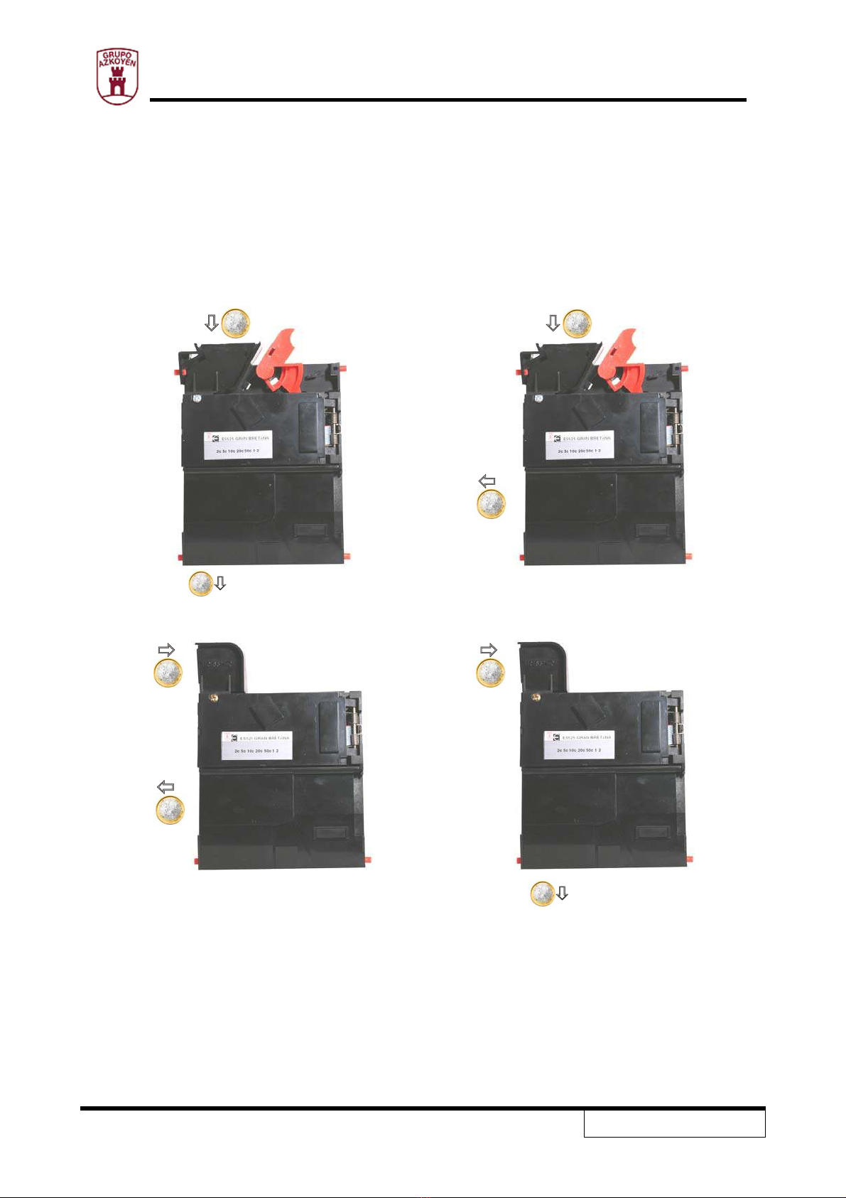
xOnce a coin is inserted, the validator looks at its characteristics and compares it to the
previously programmed coin tables. The result of the comparison can have two
values, valid coin (coin programmed), or coin not valid (coin not programmed). If the
coin is not valid, the validator rejects the coin and does not give a signal. If the coin is
valid, the coin acceptance process is initiated (figure 1).
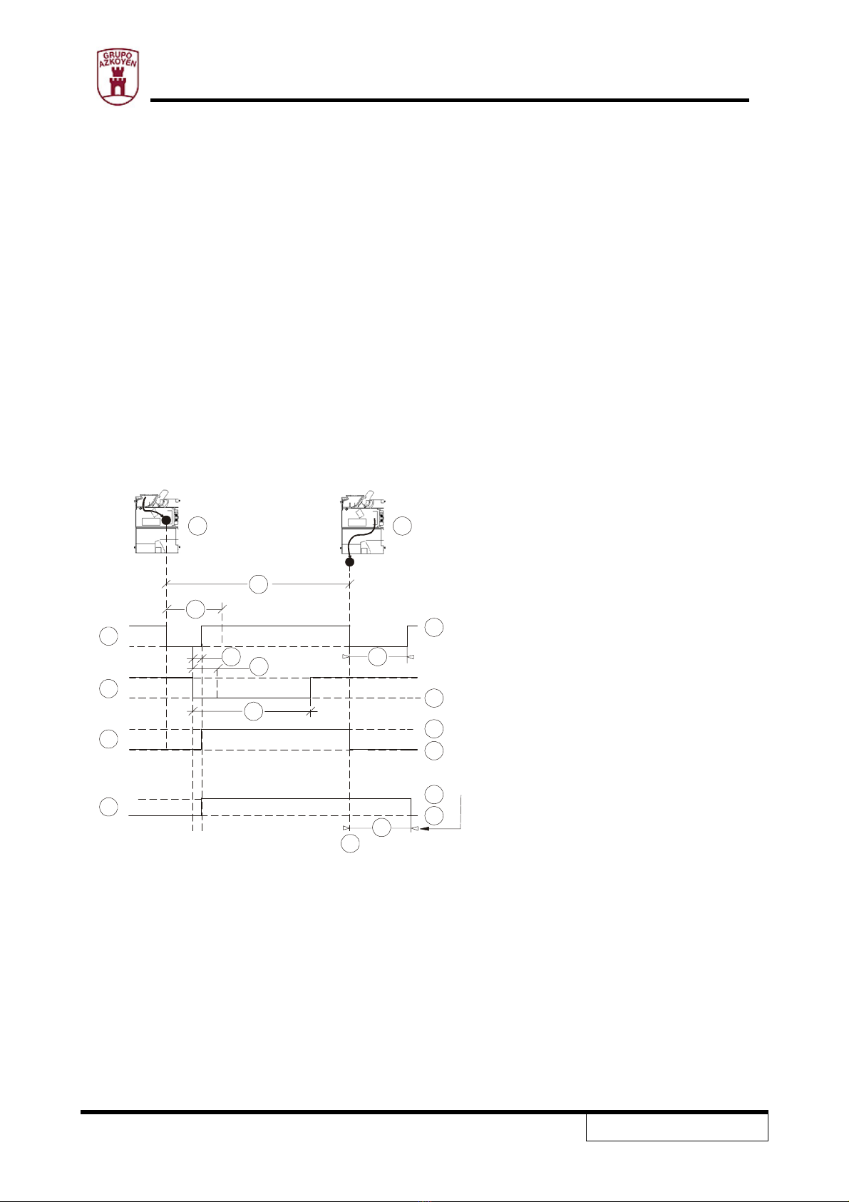
xOnce the validator has recognised a valid coin, it sends a code through the output
lines informing the machine which coin it has. The duration of this pulse is between 1
millisecond minimum to 10 milliseconds maximum.
xAt this instant and within the 10 milliseconds of the pulse the machine confirms to the
validator that it wants to admit the coin, putting the inhibition line to the selected level
for at least 3 milliseconds. If the machine does not modify the inhibition line or does
not do it within the time limit, the validator will automatically reject the coin.

10015UK 01 -2004
Technical information: ES-525 Validator 5
xOnce the validator has checked that the inhibition line has been put to the selected
level for at least 1 millisecond, it deactivates the output lines and activates the
acceptance solenoid so the coin can pass the acceptance gate as a valid coin. It is at
this moment that the validator activates the sorter.
xWhen the coin leaves the validator as a valid coin, it emits a code through the output
lines confirming that the coin has been accepted. The length of this code is
programmable between 1 and 255 milliseconds. The code that is sent is the same as
the first code sent. The inhibition line should have returned to inhibited state to be
ready for the introduction of the next coin. The maximum time between the first
signal and the confirmation signal is 1 second. If the acceptance process was correct
but for some reason the coin did not leave through the acceptance channel, the
validator will not send the second code.
xSecond code.
C
1A 2B
D
E
F
G
M
O
N
R
Q
PS
H
I
J
K
T
L
1
1
1
1
0
0
0
0
Figure 1 A. Identification of the coin.
Figure 2 B. Acceptance of the coin.
C. Coin output signal.
D. Inhibition.
E. Acceptance gate.
F. Sorter.
G. Pins 2, 4, 6, 7, 9.
H. Pin defined in the factory.
I. Open.
J. Closed.
K. Activated.
L. Deactivated.
M. IS.
N. Max. 1 sec.
O. Min. 1 ms. / Max. 10 ms.
P. 1 ms.
Q. Min. 1 ms.
R. Min. 3 ms. / Max. 220 ms.
S. 1 – 255 ms.
T. 350 – 400 ms.
ÔChanges in the output codes can be carried out as options.

10015UK 01 -2004
Technical information: ES-525 Validator 6
For both protocols, dedicated or binary, there exists the possibility of changing the output
codes for other alternatives.
An application for this may be to use the same validator for two machines whose coin
codes are different.
This mode would be activated using switch 3 (see 10.7.1).
This function is incompatible with pulse mode for the same coin, although both could
coexist for different coins.
ÔA string detection signal can optionally be provided.
The validator can give an output code
informing on the opening of the string
detector. The string detection check is done
every 100 milliseconds. The validator
maintains the active signal while the detector
is open.
During the parameter reading and admission
process, the detection is not made nor is any
signal emitted. String detector
ÔA coin recuperation signal can be provided as an option.
The validator can give an output code informing
on the opening of the validator door. The margin
necessary to give the signal is programmable.
This signal will remain active while the door is
open. During coin admission or measuring, this
signal is not emitted.
ÔA 4-way sorter capable of routing the coins through 4 different channels can be coupled
to the validator. The user can re programme the exits of the sorter.

10015UK 01 -2004
Technical information: ES-525 Validator 7
ÔIt has a sorter override.
This allows the machine to override the orders of the validator and sent the coin through
a different channel.
The validator is programmed with a sorter override, but this can be modified by the user.
The most common use of this override is diverting coins from the hopper to the cash box
when the hopper is full.
ÔIt can work using dual coin entry.
The dual coin entry consists of a double front plate and coin guide and is able to
distinguish through which entry the coin came in. The coin guide has sensors in both
channels that detect the coin as it passes and inform the validator.
One application may be to dedicate one entry for coins and the other for tokens.
This option can be deactivated using dipswitch 6 (see 10.7.4)
Double coin entry Double coin guide
ÔThe acceptance of coins can be inhibited by the machine and also by the validator. The
machine inhibition is through the input inhibition line and the validator by activating the
corresponding dipswitch.
ÔOptionally the validator can send error messages on the following occasions:
xCoin exit detectors continually covered.
xMeasurement detectors continually covered.
xCoin rejected by string detector system.

10015UK 01 -2004
Technical information: ES-525 Validator 8
xValid coin too long in exit sensor.
xValid coin not reached exit sensor.
xValid coin reached exit sensor too soon.
Cancelling error alarms is carried out with dipswitch 5 (see 10.7.3).

10015UK 01 -2004
Technical information: ES-525 Validator 9
1.2. DESCRIPTION OF COMPONENTS
1
23
4
5
67
8
91110
12 13
1. Anchorage pivots
Fixing points of the validator to the interior of the machine, the ø is 4.5 mm and the length
is 5 mm.
2. Coin return lever
Pressing this part will open the Validator door, which will eliminate possible coin jams inside
the validator.
3. Validator door
This is the moving part of the validator. When the coin return lever is pressed, it opens.
4. Circuit board cover
It is designed to protect the printed circuit board on the validator.
5. Rocker
This element catches the coin and slows it down so that all coins pass through the validator
at the same speed, which makes all measurements more accurate.
6. Metal ramp
This is hit by the coin to produce a sound collected by the acoustic sensor.

10015UK 01 -2004
Technical information: ES-525 Validator 10
This measurement provides the sound
parameters related to frequency and
amplitude of the signal.
Microphone
FRECUENCI
A
Legal coinage: Made from hard metals and
have the characteristic of long, high pitch
sounds.
FRECUENCIA
Frauds: Made from soft metals that are
easier to transform, they have the
characteristic of short, low pitch sounds.
7. Inductive sensors
They obtain coin parameters related to the coin alloy and thickness.
Inductive sensors
8. Infrared sensors

10015UK 01 -2004
Technical information: ES-525 Validator 11
They obtain the parameters related to the diameter of the coin.
Infrared barrier
9. Anti-return
Its function is to impede the return of the coin once it has been accepted.
Anti-return open Anti-return closed
10. Outlet sensor
Placed below the coin-accepted exit, this is the last check the validator does to verify the coin
has completed its cycle through the validator correctly.
11. Acceptance gate
When the validator validates a coin, an electromagnet pulls the gate open letting the coin pass
through the acceptance channel.
12. Circuit board
The electronic components necessary for the validator to carry out its function are on this
board, as well as the connectors for connection to the machine and the dipswitches for the
corresponding programming.
13. String detector
The electro-mechanical system detects any fraud attempt using the coin tied to a string
method. It works by using an infrared beam that passes through a hole in the rocker placed
over the coin entry. When the string tenses, it moves the rocker breaking the infrared beam

10015UK 01 -2004
Technical information: ES-525 Validator 12
which the Coin validator interprets as a fraud attempt and does not validate the coin. The
fraud signal is maintained while the beam is interrupted.
The Coin validator analyses the string detector status every 100 milliseconds.
A. Photodiode
B. Phototransistor
C. Infrared beam of the photodiode
D. Coin passing the string detector
AC
B
D

10015UK 01 -2004
Technical information: ES-525 Validator 13
2. OPERATING PRINCIPLES
2.1. COIN ADMISSION DIAGRAM
The covers that on the validator that give access to the measurement elements have been
removed to be able to better see the whole process of the coin inside the validator.
Introduce a coin in the validator.
The string detector activates and will only
validate the coin if it returns to its original
position.
On hitting the metal ramp, the coin makes a
sound, which is captured by the microphone
and then contrasted with that in the software.
The first diameter measuring photocell
detects the coin going past.

10015UK 01 -2004
Technical information: ES-525 Validator 14
When the second photocell detects the coin,
its diameter measurement is complete.
The coin is being analysed by the ferrite coils
at the same time.
The coin pushes past the anti-return gate that
returns to its initial position to stop the coin
from returning.
If the coin is rejected, the acceptance gate
does not open and diverts the coin through
the rejection exit.
The solenoid activates the acceptance gate
for a valid coin.
If the coin is validated, the acceptance gate
opens.

10015UK 01 -2004
Technical information: ES-525 Validator 15
When the coin leaves the validator, it breaks
the infrared beam generated by the exit
photocells; The system detects this and the
process is finished.
Coin exit photocells
2.2. PROGRAMMING 2 TOKENS OR COINS
This function is for programming two tokens or coins without the need for any accessories.
Only the parameters of the measurements of the tokens or coins are programmed. The rest of
the parameters, (credit output line, inhibition, etc.), are established when defining the
validator. To change any of this data the tele programmer TL21 is necessary.
To enter in “auto programming” mode, the programming sequence is the following:
1. Set dipswitch 1 to indicate which token or coin is to be programmed.
Dipswitch 1 OFF: token or coin 1
87654321
Off
On
Dipswitch 1 ON: token or coin 2
87654321
Off
On
2. Short pins 2 and 3 on JP1.
13
The validator indicates that it is in “auto
programming” mode by activating the
acceptance gate solenoid for a short time
(approx. 100 milliseconds).

10015UK 01 -2004
Technical information: ES-525 Validator 16
Acceptance gate solenoid
3. Introduce the tokens or coins to be programmed, (minimum advised is 25). The tokens or
coins will be accepted if they have been measured correctly.
4. Remove the short on connector JP1. The validator indicates that it has been programmed
correctly by activating the acceptance gate solenoid for approximately 1 second. If there had
been any error in programming the validator, it would not activate the solenoid. If the
programming was carried out correctly, the validator can now accept the programmed tokens
or coins (it is not necessary to disconnect the validator).
To erase the programming of a token or coin, simply follow the same abovementioned
procedure without introducing any tokens or coins.
If there are a large number of tokens or coins rejected, re programme the validator
with the rejected tokens or coins included in the set.
The auto programming function has been designed to programme any type of metallic
disk, whether it be a token or coin. The result obtained will be better the higher the
quality and uniformity of the tokens or coins used.
We recommend tokens or coins that are not magnetic, with a uniform dimension, alloy
and stamp and that do not have protrusions greater than the rim of the coin.

10015UK 01 -2004
Technical information: ES-525 Validator 17
3. CLEANING AND MAINTENANCE
The amount of dirt coins leave and the foreign objects and dirt that may obstruct its elements
determine the maintenance the coin validator requires. Use the following guidelines for
cleaning:
zDisconnect the power.
zClean the dirty areas with paint brush or brush with fine vegetable fibres (never metal)
impregnated with alcohol. Thoroughly clean the coin entry channel, metal ramp and the
optic sensor windows.
WARNING:
Internal parts that are held with screws should never be dismantled. Their manipulation may
result in alignment problems that provoke errors in measurement.
Never use products that contain benzene hydrocarbons. These products severely degenerate
the plastic parts producing irreparable damage.
Never submerge the Coin validator in any liquid.
The only maintenance required by the user is to clean the coin channels and the optic sensor
openings.
Photocells in body Photocells in cover Optic sensors for coin exit
Never use water, detergents, abrasives or thinners for cleaning this equipment.

10015UK 01 -2004
Technical information: ES-525 Validator 18
4. WORKING CONDITIONS AND NORMS
ÔTemperatures:
ÔStorage: from -25 to +70ºC.
ÔWorking: from +5 to +55ºC.
ÔHumidity: maximum 95% (relative humidity without condensation)
ÔInstall the E525 coin validator with a maximum inclination of +/- 3ºon all axes.
+/- 3º
ÔIt meets the directives corresponding to “CE” norms:
Electromagnetic emission
zEN50081-1. General emission norm.
zEN50022: Radiated emission (measurement of the radiated perturbation field).
zEN50022: Conductive emission (measurement of the conductive perturbations
in power supply).
Electromagnetic immunity
zEN50082-1: General immunity norm.
zIEC801-2: Electrostatic discharges (measurement of the immunity to
electrostatic discharges).
zIEC801-3: Radiation immunity (measurement of the immunity to electric
fields).
zIEC801-4: Transitory peaks and spikes (Measurement of the immunity of
transitory peaks and spikes).
zEN60335-1 (94-95): electrical appliance safety norm.

10015UK 01 -2004
Technical information: ES-525 Validator 19
ÔCE
Table of contents