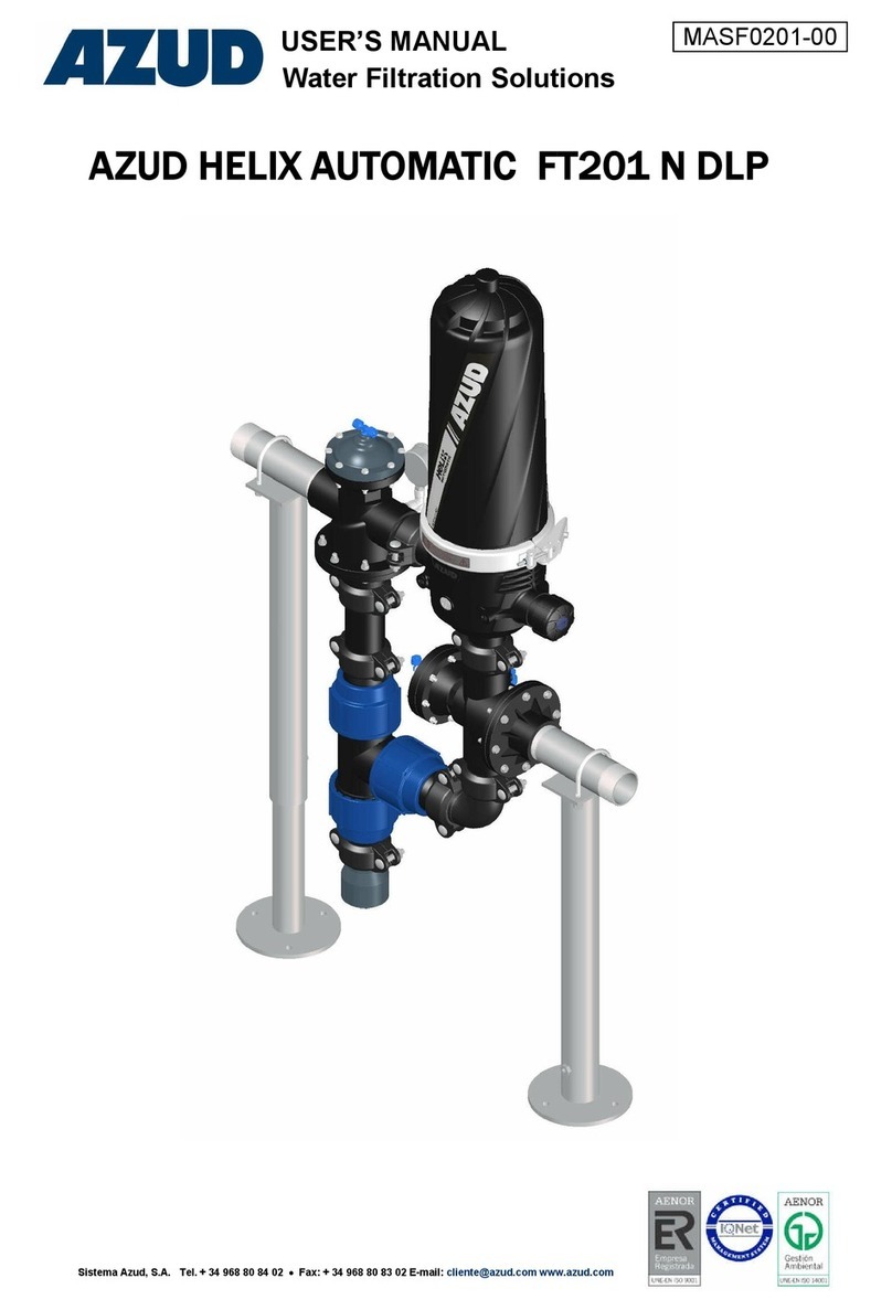
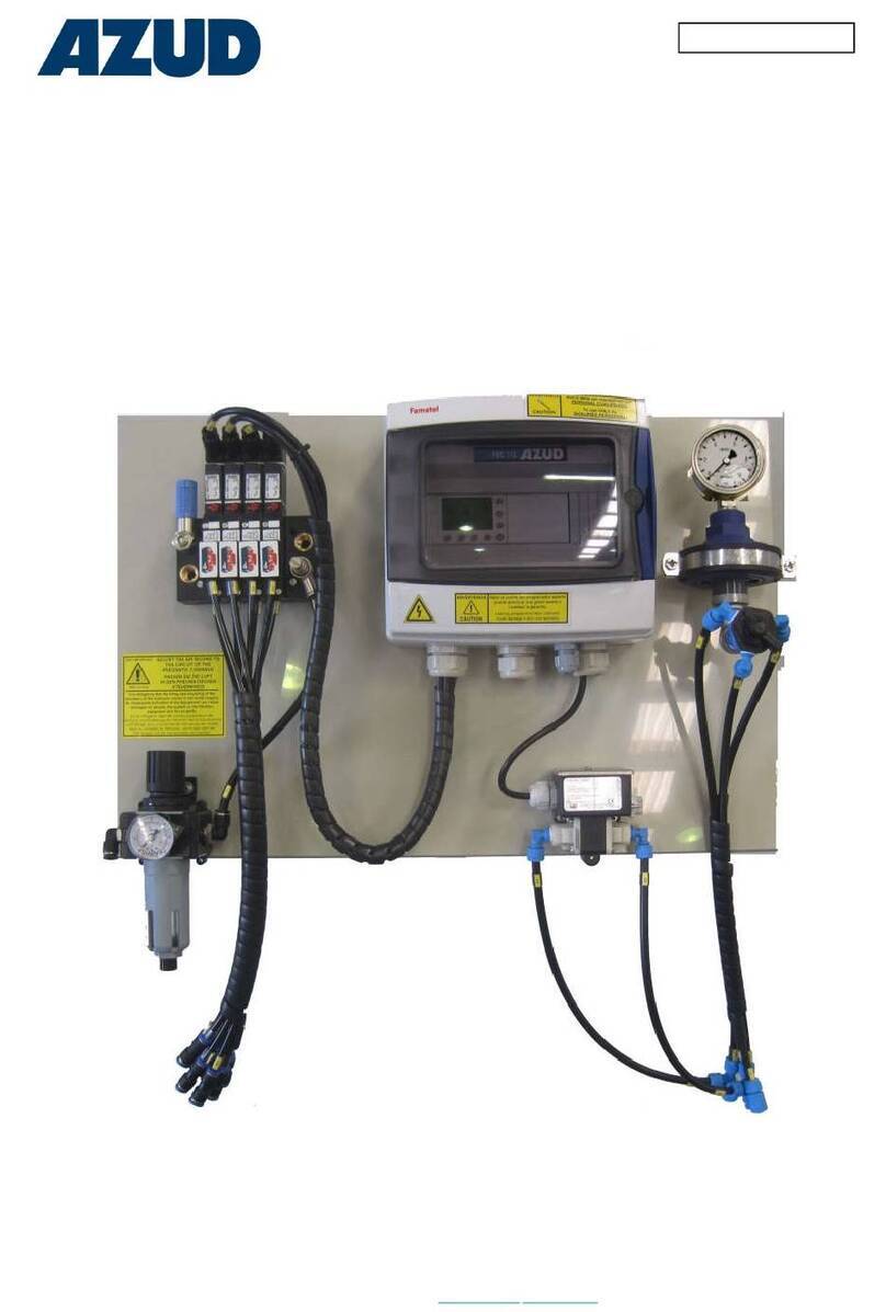
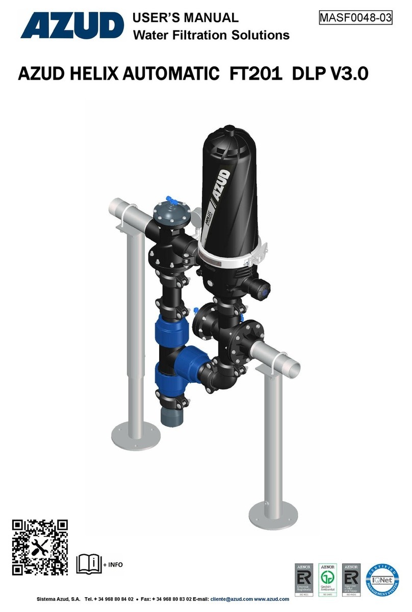
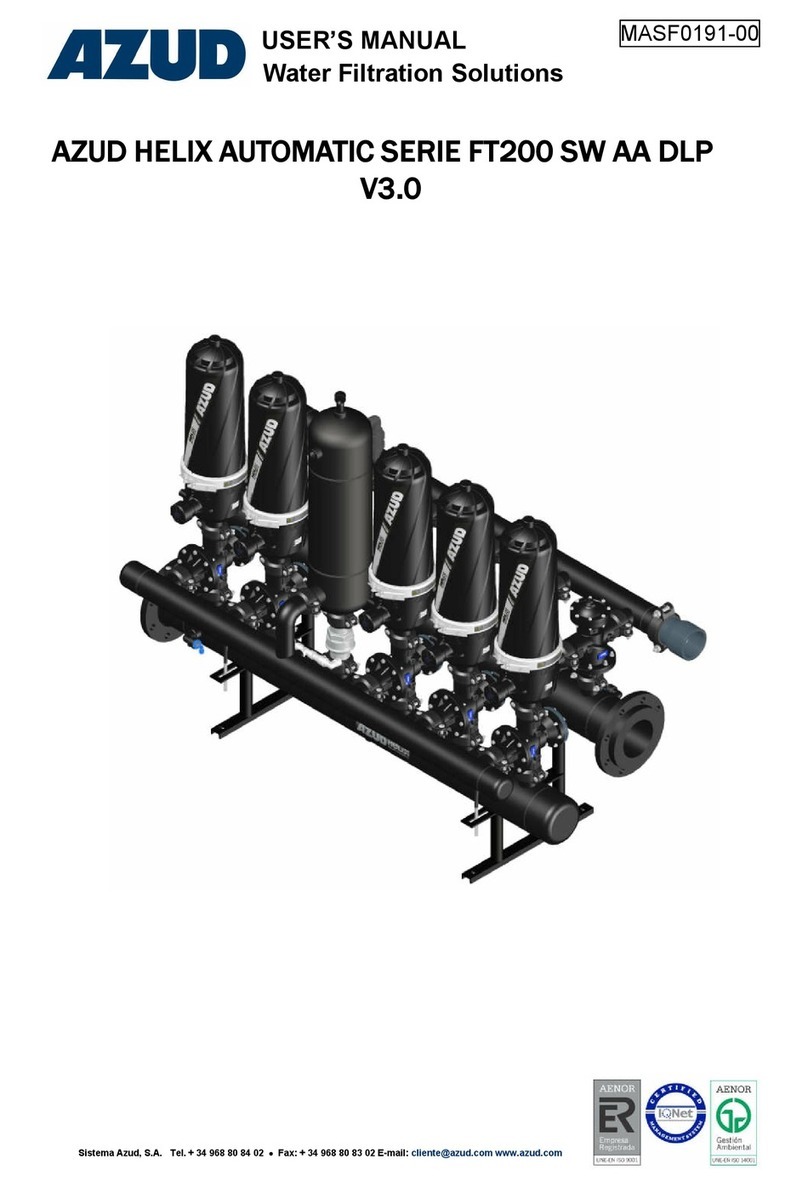
AZUD HELIX AUTOMATIC FT201 AA DLP User manual

AZUD HELIX AUTOMATIC FT201 AA DLP
MASF0136-05
USER’S MANUAL
Water Filtration Solutions
Sistema Azud, S.A. Tel. + 34 968 80 84 02 Fax: + 34 968 80 83 02 E-mail: [email protected] www.azud.com

System of symbols used in this manual:
In the reading of this manual you will find some signs used as information points to warn and to identify
risks. This is the format and content of these messages:
It Indicates instructions and warnings which failure to follow could cause
damages to people, the Equipment and its surroundings.
All information, illustrations and specifications in this catalogue are based on
the latest information available at the time of publication, and shall not be
construed as a commitment of AZUD.
AZUD may alter, remove or change the content of this document without any
further notice, and shall not assume any responsibility for errors that may
appear in this document. The Spanish version of this catalogue will prevail over
the versions of the document that can be made in different languages.

1. INTRODUCTION
2. FEATURES OF THE FILTRATION EQUIPMENT
2.1 Exclusive use of the Filtration Equipment.
2.2 Identification of the Product.
2.3 Operation Description.
2.4 Components and Spares.
2.4.1 AZUD HELIX AUTOMATIC Filter.
2.4.2 Backflushing Valves.
2.4.3 Inlet and Outlet main manifolds.
2.4.4 Drainage Manifolds.
3. TECHNICAL DATA
3.1 AZUD HELIX AUTOMATIC General Features and requirements. Serie 200.
3.2 Dimensions and weighs.
3.3 Azud Helix Automatic Filter.
4. SECURITY INFORMATION
5. INSTALLATION INSTRUCTIONS.
5.1. Separation of the Equipment from the pallet.
5.2 Fastening the equipment to the floor.
5.3 Connection of the manifolds of the equipment.
5.4 Pneumatic connection to the air system
6. OPERATION INSTRUCTIONS.
6.1 Start-up AZUD HELIX AUTOMATIC equipment.
6.2 Opening and closure of AZUD filters.
7. MAINTENANCE INSTRUCTIONS.
7.1 Maintenance Chart.
7.2. General inspection of the Equipment
7.3 Inspection of the filters
7.3.1 Cleaning of discs
7.3.2 Inspection of the gaskets.
7.3.3 Inspection of the movable elements of the base of the filtering element.
7.3.4 Inspection of the Piston elements
7.4 Inspection of the components.
7.4.1 ¼” Intake filter inspection.
7.4.2 Grooved couplings maintenance.
8. POSSIBLE PROBLEMS –CAUSES –SOLUTIONS.
9. WARRANTY.
INDEX
4
4
12
12
13
16
17
23
26

Water Filtration Solutions
4
2. Features of the Filtration System.
1. Introduction.
Thank you for trusting in AZUD HELIX AUTOMATIC equipments to solve your filtration
requirements. Please read carefully this manual and you will find answer to most of your questions.
IF YOU HAVE ANY QUESTION OR NEED ADITIONAL INFORMATION; PLEASE CONTACT US IN
+34 968808402 OR azud@azud.com
All the equipments manufactured in Sistema AZUD are subject to strict quality control tests and are
manufactured under a productive process which complies with the requirements of the standard ISO
9001/2000.
Sistema AZUD is also committed with the environment, and is certified under the Environmental
Management System of the standard ISO 14001.
This manual includes instructions and warnings to a correct installation, operation
and maintenance of the Equipment.
2.1. Exclusive Use of the filtration Equipment.
Sistema AZUD filtration equipments have been designed to exclusively filter water,
according to the Operational Conditions indicated in the Technical data and the
Industrial label of the Equipment. In any case to the filtration of dangerous liquids
(understood as such the specific in the charter 2 of article 2 of Directive
67/548/CEE, of 27th of June of 1967), or liquids for food use.
CLASSIFICATION ACCORDING TO THE DIRECTIVE OF PRESSURE
EQUIPMENTS.
PED 2014/68/EU –Fluid Group 2

Water Filtration Solutions
5
2.2. Identification of the product.
In AZUD each filtration equipment is identified by an industrial label, placed in one of the main
manifolds, with the serial number. With this number the factory can always identify the equipment.
The modification or elimination of this label cancels any warranty; and impedes the
identification of the Equipment.
The industrial label indicates: manufacturer, address, model, year of manufacturing, serial
number, max. Pressure, max. Temperature and conformity with the Directive of Pressure
Equipments PED 2014/68/EU.
The label includes QR code to access the technical documentation of the product such as
technical sheets, user manual, spare parts and/or maintenance and commissioning instructions.
The filters of the equipment,
are identified with a label in
which is indicated the model,
year of manufacturing, serial
number and max pressure.
AZUD HELIX AUTOMATIC consists of a filtering element which
comprises grooved discs, that allow the retention of particles of a size
bigger than the required filtration grade. The Equipment combines the
advantages of the disc filters with those of the helical-centrifugal effects
of the helix.
AZUD grooved discs combine on-surface filtration and in-depth
filtration to achieve the maximum precision and safety in the
filtration.
The particles are retained through the channel of the discs.
DISCS
2.3. Operation Description.

Water Filtration Solutions
6
TECNOLOGY
The system carries out two independent phases in each
filtering unit but simultaneous in the filtration system in
precise moments. This is called FILTRATION PHASE
and BACKFLUSHING PHASE
FILTRACIÓN STAGE
Once the water comes in the
filter, the only way to follow are
the channel of discs.
The outlet manifold is the
responsible to collect the filtered
water and carry it out to the
exterior of the same.
BACKFLUSHING PHASE
The programmer of the Control Unit, closes the
contact which supplies NC solenoid charge and
which is responsible for the activation of the first
station that will carry out the backflushing. The
solenoid converts the electric signal in a
pneumatic signal responsible for the feeding of
the backflushing valve chamber and auxiliary,
communicating the filtered water outlet with the
drainage.
Through the feeding of the three-way valve
chamber, the inlet of water to the filter is closed,
communicating the interior of the filter with the
drainage manifold, starting a backflush.
The start of the backflushing process takes place when
the Control Unit activates the backflushing cycle under
one of the four possible orders: Differential of
pressure, time frequency between backflushings or
manually on the keyboard or by external signal.
In the filtration process, water is carried from the
inlet manifold through the backflushing valves, to
the interior of the filter which form the filtration
system .
OUTLET
BACKFLUSHING
VALVE
AUXILIARY
VALVE
INLET
OUTLET
DRAINAGE
AUXILIARY VALVE
BACKFLUSHING
VALVE

Water Filtration Solutions
7
A moment after the following solenoid
introduces the air in the filtered water
deposit and inside the filtering element.
This mixture of water –air provokes a
hydraulic –pneumatic force which is
used to overcome the pressure made
by the spring over the stack of discs,
generating the decompression of the
same due to the rising of the piston.
The release of discs makes possible these can freely spin due to
the tangential projection of the water coming from the feeder bars
which at the same time are used as structural support of the stack
of discs.
The correct distribution of the holes in the bars, together with the
studied design of the same, project water under pressure which
tangentially falls into the discs, generating its rotation and vibration
of the same and consequentially the complete elimination of the
retained solids through the backflushing valve. These are carried to
the outside by the drainage manifold.
Once the station has completed the backflushing process, it is
repeated sequentially until it completes the totality of stations which
form the filtration equipment.
The end of the backflushing coincides with the closure of the
drainage outlet and the opening of the inlet manifold on the last
station which forms the filtration equipment. In this way the filtration
initial conditions are re-established and also the availability of the
totality of filters to carry out the filtration function.
All that available hydraulic power is used to overcome the
pressure exerted by the spring on the discs stack generating in
this way its own decompression due to the piston displacement
(raising).
BACKFLUSHING
FILTRACION VALVULA90º
FLOW
FLOW
Drainage
PISTON CAP WITH
SPRING
LOWER SIDE OF
THE FILTERING
ELEMENT

Water Filtration Solutions
8
COMPONENTS AND SPARTE AZUD HELIX AUTOMATIC EQUIPMENT
Nº COCE DESCRIPTION MATERIAL
1---------- AZUD HELIX AUTOMATIC 2”S FILTER --
2---------- AUXILIARY TANK
3---------- MANIFOLD HDPE
4---------- 3 WAYS HYDRAULIC VALVE 2”
5---------- AUXILIARY VALVE
6---------- SUPPORTS
78660121D GROOVED COUPLING 2”
8---------- AIR INJECTOR
9---------- RETENTION VALVE
10 ---------- MANOMETER
COMPONENTS AND SPARES AZUD HELIX AUTOMATIC FILTER
Nº CODE DESCRIPCTION MATERIAL un
16 17RXP010 PLASTIC LID 3" RPA 1
17 - FILTERING ELEMENT AZUD HELIX AUTOMATIC - 1
18 70RX0001 CLAMP SAFETY AZUD HELIX AUTOMATIC A. INOX. 1
19 17RXP012 SEALING GASKET BASE NBR 1
20 18R60003 BASE 2NV RPA
35 17RXP013 BASE CAP RPA
36 - O-RING CAP RPA
Please indicate the serial number of the equipment when requesting spares.
AZUD HELIX AUTOMATIC
NUMBER CODE DESCRIPTION un
17
18CN30W6 AUTOMATIC CARTRIDGE DEP 3.0 S-DISC 130 MICRON 1
18CN30W8 AUTOMATIC CARTRIDGE DEP 3.0 S-DISC 100 MICRON 1
18CN30W2 AUTOMATIC CARTRIDGE DEP 3.0 S-DISC 50 MICRON 1
18CN30W1 AUTOMATIC CARTRIDGE DEP 3.0 S-DISC 20 MICRON 1
18CN30W4 AUTOMATIC CARTRIDGE DEP 3.0 S-DISC 10 MICRON 1
18CN30W3 AUTOMATIC CARTRIDGE DEP 3.0 S-DISC 5 MICRON 1
17
18CN30X5 AUTOMATIC CARTRIDGE DEP 3.0 400 MICRON 1
18CN30X0 AUTOMATIC CARTRIDGE DEP 3.0 200 MICRON 1
18CN30X6 AUTOMATIC CARTRIDGE DEP 3.0 130 MICRON 1
18CN30X8 AUTOMATIC CARTRIDGE DEP 3.0 100 MICRON 1
1
38
69
5
2
4
5
10
7
4
16
17
18
19
20
36
35
2.4. Componentes y repuestos EQUIPO DE FILTRACION:
AZUD HELIX AUTOMATIC FT201 AA

Water Filtration Solutions
9
*: OPTION
RPA: POLYAMIDE REINFORCED WITH GLASS FIBER
PP: POLYPROPYLENE
NBR: NITRIL RUBBER
RPP: REINFORCE POLYPROPYLENE WITH GLASS FIBER
PE: POLYETHYLENE
A, INOX.: STAINLESS STEEL
AZUD HELIX AUTOMATIC FILTERING ELEMENT
WS
DISC
MG
DISC
SPARE PARTS KITS
NUMBER CODE DESCRIPTION un
23-27x2-31-32 18R60116 O-RINGS KIT AUTOMATIC FILTER 3.0 1
23-31-32 18R60117 PISTON SET OF O-RINGS AUTOMATIC FILTER 3.0 1
23-27x2-29-31-32 18R60118 MAINTENANCE KIT AUTOMATIC FILTER 3.0 1
20 18R60119 FRAME AUTOMATIC FILTER DEP 3.0 1
25x2-26x2 18R60120 CHECK VALVE AUTOMATIC FILTER 3.0 1
26 ---------- STEM CHECK VALVE 1
27 18R60026 O RING 103X4 2
28 ---------- A PISTON COMPONENT 1
29 ---------- SPRING 1
30 ---------- B PISTON COMPONENT 1
31 ---------- O RING 13X2 2
32 ---------- CLIP 1
33 17RXP020 HELICAL ELEMENT 1
Please indicate the serial number of the equipment when requesting spares.
AZUD HELIX AUTOMATIC DISC KIT
NÚMERO CÓDIGO DESCRIPCIÓN un
22
18R60033 S-DISC KIT AUTOMATIC FILTER 130 MICRON 1
18R60039 S-DISC KIT AUTOMATIC FILTER 100 MICRON 1
18R60034 S-DISC KIT AUTOMATIC FILTER 50 MICRON 1
18R60035 S-DISC KIT AUTOMATIC FILTER 20 MICRON 1
18R60038 S-DISC KIT AUTOMATIC FILTER 10 MICRON 1
18R60036 S-DISC KIT AUTOMATIC FILTER 5 MICRON 1
22
18R60040 DISC KIT AUTOMATIC FILTER 400 MICRON 1
18R60012 DISC KIT AUTOMATIC FILTER 200 MICRON 1
18R60011 DISC KIT AUTOMATIC FILTER 130 MICRON 1
18R60010 DISC KIT AUTOMATIC FILTER 100 MICRON 1
28
29
30
32
31
21
21
22
23
24
25
26
27
17
21
22
20
33

Water Filtration Solutions
10
H
EA1
EA2
Cod: 18CE1008
2.5 Backflushing Grooved valve 2”x2”x2”.
The reference of the backflushing valve will be different
according the manufacturer AZUD supplied in your filtration
equipment.
PLASTIC VALVE BERMAD
S1

Water Filtration Solutions
11
-To the correct working of the equipment it should have a minimum
of 6 bar to 1200 l/min in the backflushing process.
-The maximum pressure of air intake should not surpass the 7 bar.
To adjust the inlet pressure of the air intake it should be taken into account the inlet pressure
of water in the filtration equipment. The maximum pressure of air intake should be equal to the
maximum inlet pressure of water to the filtration equipment plus 1 bar.
Air intake P = inlet water P + 1bar
It is not necessary the use of lubrication in the air treatment of the pneumatic command. It can
even damage some components.
The instructions and warnings should be taken into account in order to obtain a correct
installation, working and post-working of the Equipment.
Not obeying the instructions or warning can cause damages or failure in the working of the
equipment.
Backflushing Volume per filter 10 l / 2.64 gallons
Minimum pressure 0.8 bar / 11.60 psi
3. Technical Data
3.1 AZUD HELIX AUTOMATIC 201 AA General features and requirements.
Data with 0 bar pressure in the drainage manifold.
The differential pressure of the filter never must be higher than 0.2-0.3 bar
over the value of the filter has when it is clean
Maximum working pressure 10 bar
145 psi
Maximum Temperture 60ºC
140ºF
pH 4-11
2”SUPER
FILTRATION 400
micron 200
micron 130
micron 100
micron 50
micron 20
micron 10
micron 5
micron
QUALITY OF WATER
GOOD WATER 28 m3/h
123,27 gpm 27 m3/h
118,87 gpm 26 m3/h
114,47 gpm 24 m3/h
105,66 gpm 14 m3/h
61,63 gpm 8 m³/h
35,22 gpm 6 m³/h
26,41 gpm 5 m³/h
22,01 gpm
ERAGE WATER 26 m3/h
114,47 gpm 25 m³/h
110,07 gpm 24 m3/h
105,66 gpm 22 m3/h
96,86 gpm 13 m3/h
57,23 gpm 7 m3/h
30,81 gpm 5 m³/h
22,01 gpm 4 m³/h
17,61 gpm
POOR WATER 24 m3/h
105,66 gpm 23 m³/h
101,26 gpm 22 m3/h
96,86 gpm 20 m3/h
88,05 gpm 12 m3/h
52,83 gpm 6 m3/h
26,41 gpm 4 m³/h
17,61 gpm 3 m³/h
13,20 gpm
Y POOR
WATER 22 m3/h
96,86 gpm 21 m³/h
92,45 gpm 20 m3/h
88,05 gpm 18 m3/h
79,25 gpm 11 m3/h
48,43 gpm 5 m3/h
22,01 gpm 3 m³/h
13,20 gpm 2 m³/h
8,80 gpm

Water Filtration Solutions
12
D
X
W
H
M
C
A
B
E
3.3.- General Characteristic AZUD HELIX AUTOMATIC Filter.
3.2.- Dimensions of AZUD HELIX AUTOMATIC Equipment.
Connections Dimensions (mm)
A B C E M H W X D
2” VIC 2” VIC 2” BSP ¾” BSP ¼” BSP 721 309 133 245
The failure to obey the instructions and
warnings could cause damage to people,
the equipment and the surrounding area.
CLASSIFICATION ACCORDING TO THE DIRECTIVE OF
PRESSURIZED EQUIPMENTS
PED 2014/68/EU –Fluid Group 2

Water Filtration Solutions
13
4. Security Information
Sistema AZUD filtration systems have been designed for the filtration of water
following the Operation Conditions indicated in the Technical Data and in the
industrial label of the Equipment.
Sistema AZUD filtration systems are NOT designed for the filtration of hazardous
liquids (such as those specified in section 2 of article 2 of the Executive Committee
67/548/CEE, 27th June 1967)or liquids for food use.
This is not an standard Equipment. It has been designed and manufactured to
satisfy the requirements communicated to the manufacturer by the customer. Any
additional requirement or change in its use could cause damages not covered by
the warranty.
Preserve this manual so that the user of the Equipment could familiarize with it.
Below there are some general instructions for a safe operation of the Equipment.
These instructions are not a close list, the user must adopt as many security
measures as necessary to guarantee his security. In this way, this safety
information does not substitute the accident emergency measures which should be
adopted.
Follow the instructions described in this manual.
Do not open the filter clamp when the Equipment is pressurized, it could cause a
deep damage on people, the Equipment and the surrounding area.
Do use the adequate personal protection (adequate clothes, protective glasses and
other elements of personal protection...).
Determine the chemical compatibility between the Equipment materials and the
characteristics of the water to be filtered.
Before starting the Equipment, make sure that all the covers are closed properly and
the connections are in good conditions.
Make sure that the Equipment is depressurized (through the reading of the gauges
of the filters inlets and the outlet manifold gauge) before coming into contact the
interior of the Equipment with the atmosphere (before opening any filter, removing
any coupling, etc)
Do not forget to lock the safety lock of the clamp. It will avoid its accidental opening.
Do not exceed the maximum and operation intervals (pressure, temperature, pH, and
flow rate) indicated in the Technical Data.
In freezing risks areas, do empty the filtration system to avoid damages.
The Warnings and Safety Information are for guidance only, just carry them out taking
as many security measures and prevention of accidents as possible to guarantee your
security.
The inappropriate use of the Equipment may cause damages on people, the property
and the environment. A bad use or modification in the Equipment cancels its warranty

Water Filtration Solutions
14
5. Installation Instructions.
AZUD HELIX AUTOMATIC equipment is delivered already assembled on a pallet. In the installation
the steps to follow reduced to:
1- Transport the filtration equipment with the pallet with a lift truck or similar until its final emplacement.
2- Unpack the equipment carefully and check there are not damages in the same.
3- Confirm all the specified parameters are agreed with the ones of the equipment.
-Installation should be made by QUALIFIED STAFF.
-The location of the Equipment should be made on solid ground.
You should take into account the weight of the Equipment when you
choose the ribbons or synthetic slings. See the Technical Data section.
-Make sure that the measures of the ribbons of the raising system are
correct so that the equipment is in an horizontal position when raised.
Secure the Equipment to the raising system to avoid accidents.
Follow the operation and safety instructions of the Manual
In case of doubts please contact us.
5.2. Connection to the installation.
The connections are grooved. You should use the necessary and standard elements to connect the
Equipment with the rest of the installation.
Fix the Equipment to the ground: If you want to fix it, you can do it with the appropriate lag screw
according to the kind of ground. The lag screw should be placed in the holes of the level regulators.

Water Filtration Solutions
15
5.3. Connection of the Equipment to the Control Unit through the union of the homologous
microtubes.
The homologous union microtubes are labelled according to the following nomenclature:
* GLOSSARY
STATION We understand by station each of the groups of filters which backflush altogether
in the same signal of the Control Unit. An station can be formed by one or several
filters.
PRESSURE
DIFFERENTIAL
GAUGE
It indicates in the graduated sphere the differential pressure value between intake
P1 and P2 as well as the stipulated value through which it is established the
contact for the activation of a backflushing.
COMMAND DESCRIPTION: Use and Connection
TPRESSURE INTAKE:To the feeding of the whole circuit of pneumatic command. It should
correspond with the place of highest pressure of the whole installation. It takes the air from
its compressor.
TA AUXILIARY PRESSURE INTAKE:To the feeding of the pneumatic command circuit, which
allows the manoeuvre of 3/8”valves and relay.
HAUXILIARY ESCAPE: Pneumatic command which allows the exit of air of the auxiliary
cleaning deposit to the filling of water.
P1 Pressure intake in inlet manifold,to be connected to the differential pressure gauge*.
P2 Pressure intake in the outlet manifold,to be connected to the differential pressure
gauge*.
EA Auxiliary Station: Pneumatic command in charge of the air feeding to the equipment when
the backflushing process and the drainage of the same is activated in the instant the
activation of the electrovalve stops.
EA1 Auxiliary Station 1: Pneumatic command in charge of the air feeding to the auxiliary
deposit.
EA2 Auxiliary Station 2: Pneumatic command in charge of the air feeding to the filtering
element through one injector.
EEA Feeding pneumatic valve: Pneumatic control manager feeding air into the chamber of the
pneumatic angle seat valve
En Station 1: Pneumatic command in charge of the hydraulic relay feeding and/or chamber of
three ways to the activation of backflushing station* or filter n.1, and the drainage of the
same in the instant the activation of electrovalve nº1 stops.
E3 ... En ....
Sn ESCAPE: Command to the movement of the valve at the instant in which the activation of
the station* or corresponding filter.

Water Filtration Solutions
16
5.4 Pneumatic connection between the Control Unit and the pressurized air
equipment.
Connect the intake source
of air to the control Unit.
To make this connection
we leave in the pressure
regulator a 12 elbow of
quick coupling.
INTAKE OF AIR “T” TO
THE CONTROL UNIT
This control unit has a needle valve to adjust the inlet pressure of the two stations grouping.
This device is adjusted from the factory.
-To the correct working of the equipment it should have a minimum
of 6 bar to 1200 l/min in the backflushing process.
-The maximum pressure of air intake should not surpass the 7 bar.
To adjust the inlet pressure of the air intake it should be taken into account the inlet pressure
of water in the filtration equipment. The maximum pressure of air intake should be equal to the
maximum inlet pressure of water to the filtration equipment plus 1 bar.
Air intake P = inlet water P + 1bar
It is not necessary the use of lubrication in the air treatment of the pneumatic command. It can
even damage some components.
The instructions and warnings should be taken into account in order to obtain a correct
installation, working and post-working of the Equipment.
Not obeying the instructions or warning can cause damages or failure in the working of the
equipment.
TH
EA1
EA EA2D
EEA TA

Water Filtration Solutions
17
6. Operation Instructions
BEFORE THE STARTING-UP
Make sure that the flow rate, pressure, temperature and pH will be covered by the Equipment
specifications (indicated in the Equipment technical data) when starting it.
Make sure that all the filters are properly closed and there are no leakages.
Make sure that the auxiliary filter key is opened.
START-UP
Connect the pumping system for the water inlet
Make sure that the Operation Conditions (pressure, temperature, flow rate and pH) are on the
specifications.
Watch the Equipment head loss
.Follow the instructions of the Equipment's Control Unit Manual.
Instructions to the operation of the equipment:
6.1- Start-up AZUD HELIX AUTOMATIC.
-Do not operate out of the working Conditions.
-Be sure the auxiliary Filter key is open before starting-up the Equipment.
6.2- Opening and closure of the filters.
Pressure Equipment: Be sure the filter is depressurized before opening it.
2. Take away the lid of the filter
1. Take away the clamp.
1- Turn the screw
and remove the anti-
opening device (if
you have the same)
2- Rise-up the lever
and take out the
bolt.
Anti-opening
device
Safety screw of the anti-
opening device
lever
SAFETY CLAMP
1. Check the O-ring is clean
2. Correctly close the filter
If leakages, adjust the closure of the clamp.
3. Adjust the closure with the
screw

Water Filtration Solutions
18
- Pressure equipment: Make sure that the filter is depressurized before opening it.
-For the Equipment's operation, use the adequate personal protection (adequate
clothes, protective glasses, gloves and other elements of personal protection ...).
-Do not forget to adjust the safety lock of the clamp. It will avoid its accidental
opening.
-It is recommended the installation of an upstream and downstream valve to
isolate the system during maintenance operations.
7. Maintenance Instructions.
Maintenance Plan of the Equipment.The period between revisions depends on the operation
conditions, characteristics of water to be filtered, operation hours, number of backflushings, recuperation
of the differential pressure after the backflushings…. AZUD recommends three months between the
different revisions of components which imply the disassembly of the filtering element. This period
should be determined by the user according to the particular characteristics of his installation.
-Be sure the Equipment is depressurized before making any operation which
expose in contact the interior of the equipment with the atmosphere.
-The maintenance labours should be made by qualified staff.
For the identification of the components check section 2.5 of the manual
DAILY ACTIONS
1. Visual inspection of the Equipment
2. Checking there are not leakages in the Equipment
3. Checking of the Operation Conditions (pressure, temperature, flow rate, pH).
4. Vigilance of the Equipment head loss (P1* - P2*)
PERIODICAL ACTIONS
1. Checking of the base o-ring
2. Checking of the filters cleaning state. If they are too dirty, clean the discs manually.
3. Manual activation of a backflush to check that the backflushing phases of all the stations are
carried out correctly.
4. Gaskets checking
5. Checking the elements of the piston.
6. Checking of ¾” auxiliary Filter
7. Checking ¼” intake filters.
8. Maintenance of grooved couplings.
7.1 Maintenance Summary Box.
* : P1 and P2 are the pressure in the inlet and outlet manifold. Their difference is the head loss of the Equipment.
-The checking period should be determined by the user according to the particular
characteristics of its installation

Water Filtration Solutions
19
7.2. General Revision of the Equipment.
1. Open the clamp and take
away the lid
O-RINGS
92,6x100x4.0
O-RINGS
103x4.0
The maintenance plan of the filter depends on the working conditions of each installation which should be
determined by each user. The steps of the maintenance plan are:
IMPORTANT WS DISC
Striated side
The same side of two WS DISC
can never be together.
2. Remove the filtering element
carefully. 3. Turn the piston until it
is released; take it away.
4. Clean only the
discs using clean
water or an acid
dissolution
Do not mixture
discs from
different filters.
5. Take away the discs.
6. Lubricate the filtering
element’s o-rings, with
neutral Vaseline if
possible.
7. Place ALL the discs.
8. It is recommended
to introduce the WS
Discs in the cartridge
with the striated side
faced down.
9. Thread the piston making a soft
pressure at the same time it is
turned to its adjustment.
10. Insert the
filtering element
safety, push
down

Water Filtration Solutions
20
7.3.2.- Checking of the movable elements of filtering element base (cap of discs, spring and
spring holder.
1. Open the clamp and take away the lid carefully: take away the filtering element. (see section
Cleaning of discs).
If you have any doubt please contact us.
7.3.1.- Checking of the filtering element 92,6x100x4 and 103 x 4 O-rings
1. Open the clamp and take away the lid of the filter carefully; take out the filtering
element; turn the piston until it is released and take it away.
2. Check the estate of the filtering element O-rings.
3. Thread the piston of the filtering element making a slight pressure and turn to its
adjustment.
4. Lubricate the area of the O-rings (see picture in the right).
5. Introduce the filtering element pushing carefully in the base of the filter.
6. Place again the lid and close the clamp.
92,6x100x4 O-RING
103x4.00 O-RINGS
In long stop periods, the O-rings should be lubricated. Furthermore, the state of the internal
components of the filter should be checked.
7.3. Maintenance filtration element
2. Check opening and closing of
the two parts of the clapper. 3. Clean carefully with water
4. Lubricate the gasket of the base of the filter
element, with a product chemically compatible
with the filter material. Insert the filter element by
pushing it gently. (See sections 6.3 and 6.4 of the
section Cleaning discs).
5. Fit the lid and close the clamp (See section
Opening and closing the filters).
Table of contents
Other AZUD Water Filtration System manuals
Popular Water Filtration System manuals by other brands

Pure-Pro
Pure-Pro ERO-S7 PERFECT WATER SERIES user manual

Pentair
Pentair OMNIFILTER OT32 installation instructions

Oase
Oase Filtoclear 3000 operating instructions

Franklin Water Treatment
Franklin Water Treatment PKLX Series Installation instructions and owner's manual

acerpure
acerpure ZC.X01TG.06J user manual

GE
GE GXRV10ABL01 Owner's manual and installation

Schaffner
Schaffner ECOsine active FN3420-030-3 Series Operating and installation instructions

Mitsubishi Electric
Mitsubishi Electric PAC-TS70TB installation manual

CSI
CSI Duplex SD48 Installation & operation manual

Eddy Home
Eddy Home WMS product manual

THORLABS
THORLABS MDFM-QFXL Assembly manual

BWT
BWT PRO A manual