AZUD HELIX AUTOMATIC FT201 DLP V3.0 User manual

MASF0048-03
USER’S MANUAL
Water Filtration Solutions
Sistema Azud, S.A. Tel. + 34 968 80 84 02 Fax: + 34 968 80 83 02 E-mail: clie[email protected] www.azud.com
AZUD HELIX AUTOMATIC FT201 DLP V3.0

Water Filtration Solutions
2
System of symbols used in this manual:
In the reading of this manual you will find some signs used as information points to warn and to identify
risks. This is the format and content of these messages:
It Indicates instructions and warnings which failure to follow could cause
damages to people, the Equipment and its surroundings.
This manual is subject to modifications without prior warning.
All information, illustrations and specifications in this catalogue are based on
the latest information available at the time of publication, and shall not be
construed as a commitment of AZUD.
AZUD may alter, remove or change the content of this document without any
further notice, and shall not assume any responsibility for errors that may
appear in this document. The Spanish version of this catalogue will prevail over
the versions of the document that can be made in different languages.

Water Filtration Solutions
1. INTRODUCTION 4
2. FEATURES OF THE FILTRATION EQUIPMENT 4
2.1 Exclusive use of the Filtration Equipment.
2.2 Identification of the Product.
2.3 Operation Description.
2.4 Components and Spares.
2.5 Backflushing Valves.
3. TECHNICAL DATA 9
3.1 AZUD HELIX AUTOMATIC General Features and requirements. Serie 201.
3.2 Dimensions.
3.3 Azud Helix Automatic Filter.
4. SECURITY INFORMATION 11
5. INSTALLATION INSTRUCTIONS 12
5.1. Separation of the Equipment from the pallet.
5.2 Adjustment of the supports of the Equipment
5.3 Fastening the equipment to the floor.
5.4 Connection of the equipment.
5.5 Neumatic connection of the equipment and the Control Unit.
6. OPERATION INSTRUCTIONS 15
6.1 Start-up AZUD HELIX AUTOMATIC equipment.
6.2 Opening and closure of AZUD filters.
7. MAINTENANCE INSTRUCTIONS. 16
7.1 Maintenance Chart.
7.2. General inspection of the Equipment
7.3 Inspection of the filters
7.3.1 Cleaning of discs
7.3.2 Inspection of the gaskets.
7.3.3 Inspection of the movable elements of the base of the filtering element.
7.3.4 Inspection of the Piston elements
7.4 Inspection of the components.
7.4.1 ¾” Auxiliary Filter inspection.
7.4.2 ¼” Intake filter inspection.
7.4.3 Grooved couplings maintenance.
8. POSSIBLE PROBLEMS – CAUSES – SOLUTIONS. 21
9. WARRANTY. 24
INDEX

Water Filtration Solutions
4
2. Features of the Filtration System.
1. Introduction.
Thank you for trusting in AZUD HELIX AUTOMATIC equipments to solve your filtration
requirements. Please read carefully this manual and you will find answer to most of your questions.
IF YOU HAVE ANY QUESTION OR NEED ADITIONAL INFORMATION; PLEASE CONTACT US IN
+34 968808402 OR cliente@azud.com
All the equipments manufactured in Sistema AZUD are subject to strict quality control tests and are
manufactured under a productive process which complies with the requirements of the standard ISO
9001/2000.
Sistema AZUD is also committed with the environment, and is certified under the Environmental
Management System of the standard ISO 14001.
This manual includes instructions and warnings to a correct installation, operation
and maintenance of the Equipment.
2.1. Exclusive Use of the filtration Equipment.
Sistema AZUD filtration equipments have been designed to exclusively filter water,
according to the Operational Conditions indicated in the Technical data and the
Industrial label of the Equipment. In any case to the filtration of dangerous liquids
(understood as such the specific in the charter 2 of article 2 of Directive
67/548/CEE, of 27th of June of 1967), or liquids for food use.
CLASSIFICATION ACCORDING TO THE DIRECTIVE OF PRESSURE
EQUIPMENTS.
PED 2014/68/EU – Fluid Group 2

Water Filtration Solutions
5
2.2. Identification of the product.
In AZUD each filtration equipment is identified by an industrial label, placed in one of the main
manifolds, with the serial number. With this number the factory can always identify the equipment.
The modification or elimination of this label cancels any warranty; and impedes the
identification of the Equipment.
The industrial label indicates: manufacturer, address, model, year of manufacturing, serial
number, max. Pressure, max. Temperature and conformity with the Directive of Pressure
Equipments PED 2014/68/EU.
The label includes QR code to access the technical documentation of the product such as
technical sheets, user manual, spare parts and/or maintenance and commissioning instructions.
The filters of the equipment,
are identified with a label in
which is indicated the model,
year of manufacturing, serial
number and max pressure.
AZUD HELIX AUTOMATIC consists of a filtering element which comprises
grooved discs, that allow the retention of particles of a size bigger than the
required filtration grade. The Equipment combines the advantages of the
disc filters with those of the helicocentrifugal effects of the helix.
AZUD grooved discs combine on-surface filtration and in-depth filtration
to achieve the maximum precision and safety in the filtration.
The particles are retained through the channel of the discs.
DISCS
2.3. Operation Description.

Water Filtration Solutions
6
FILTRATION
STAGE
INLET
OUTLET
The system carries out two independent phases called FILTRATION PHASE and
BACKFLUSHING PHASE.
TECHNOLOGY
Valve 1 Valve 2
Filtration
Stage
Backflushing
Stage
Through the feeding of the three-ways
valves chambers, the inlet of water to the
filter closes, communicating the inner of
the filter with the drainage manifold,
starting the backflushing cleaning.
BACKFLUSHING
STAGE
INLET
DRAINAGE
Valve 1
Valve 2
Special
Backflushing T
FILTRACIÓN STAGE
BACKFLUSHING STAGE
Filtration
Stage
Backflushing
Stage
LOWER SIDE OF
THE FILTERING
ELEMENT
PISTON CAP WITH
SPRING
The end of the backflushing coincides with the closure of the drainage outlet and the opening of
the outlet manifold, allowing water coming from the feeder manifold to come into the interior of
the filter and in this way, to re-establish the filtration phase conditions.
In the filtration process, water is carried from the feeder
manifold (inlet manifold), through the backflushing three-
way valve (valve 1), to the interior of the filter through its
inlet.
Once the water come in the filter, the only track the water
of its interior can follow, are the discs channels whose
discs form a stack. This stack is compressed by the spring
action and the hydraulic power itself.
The filtered water goes through the 2” hydraulic valve
and goes to the rest of the installation.
The filtered water given by the Special
backflushing T, is introduced in the filter.
The available hydraulic power is used to
overcome the pressure exerted by the
spring on the discs stack generating in
this way its own decompression due to
the piston displacement (raising).
The discs release makes possible its
rotation due to the tangential projection
of the water coming from the feeder
bars which at the same time are used
as structural shoulder of the discs stack.

Water Filtration Solutions
7
COMPONENTS AZUD HELIX AUTOMATIC EQUIPMENT
Nº DESCRIPCTION MATERIAL
1 AZUD HELIX AUTOMATIC 2”S DLP FILTER --
2 GROOVED COUPLING PVC 2” 17C20VP0
3 STAINLESS STEEL THREADED CONNECTORS -
4 SUPPORTS 18CC2010
5 GROOVED COUPLING 2” 8660121D
6 TE 90 63 2”AUXILAIRY FILTER 18CC2012
7 3 WAYS HYDRAULIC VALVE 2” 18CE1008
8 MANOMETER 17CMF010
9 COMMAND 8x6 mm – 12 mm PE
10 FILTERING ELEMENT AUXILIARY FILTER --
11 GROOVED ADAPTER TUBE AUXILIARY FILTER 2” PE
2
3
1
7
5
4
8
6
3
SPARE AZUD HELIX AUTOMATIC FILTER
Nº CODE DESCRIPCTION MATERIAL un
16 17RXP010 PLASTIC LID 3" RPA 1
17 FILTERING ELEMENT AZUD HELIX AUTOMATIC - 1
18* 17RXP011 CLAMP AZUD HELIX AUTOMATIC A. INOX. 1
18 70RX0001 CLAMP SAFETY AZUD HELIX AUTOMATIC A. INOX. 1
19 17RXP012 SEALING GASKET BASE NBR 1
20 18R60003 BASE 2NV RPA 1
35 17RXP013 BASE CAP
36 O-RING CAP 1
LA TE
6
11
6
10
2.4. AZUD HELIX AUTOMATIC SERIE FT201 DLP Components and Spares.
*: OPTION
RPA: POLYAMIDE REINFORCED WITH GLASS FIBER
PP: POLYPROPYLENE
NBR: NITRIL RUBBER
PE: POLYETHYLENE
A, INOX.: STAINLESS STEEL
Please indicate the serial number of the
equipment when requesting spares.
16
17
18
19
20
36
35

Water Filtration Solutions
8
FILTERING ELEMENT SPARE PARTS
NUMBER CODE DESCRIPTION un
21 18R60115 PISTON FRAME AZUD HELIX AUTOMATIC 1
22 --- DISCS KIT AZUD HELIX AUTOMATIC 1
23 18R60037 PISTON OGASKET92,6 x 100 x 4 mm 1
24 ---------- FRAME WIITHOUT CHECK VALVE 1
25 ---------- CHECK VALVE 1
26 ---------- STEM CLAPETA 1
27 18R60026 O-RING 103X4 2
28 ---------- A PISTON COMPONENT 1
29 ---------- SPRING 1
30 ---------- B PISTON COMPONENT 1
31 ---------- O-RING 13X2 2
32 ---------- CLIP 1
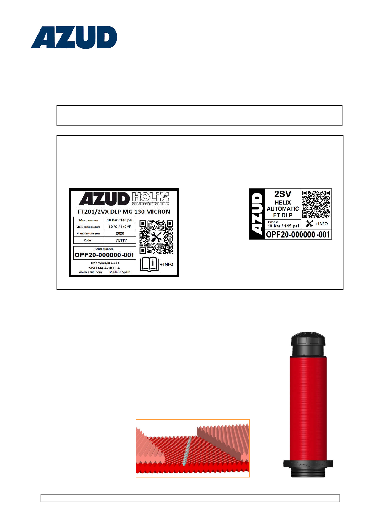
AZUD HELIX AUTOMATIC FILTERING ELEMENT
28
29
30
32
31
21
21
22
23
24
25
26
27
17
SPARE PARTS KITS
NUMBER CODE DESCRIPTION un
23-27x2-31-32 18R60116 JUEGO JUNTAS REJILLA ELEMENTO FITLRANTE 1
23-31-32 18R60117 JUEGOJUNTAS PISTON AZUD HELIX AUTOMATIC 1
23-27x2-29-31-32 18R60118 KIT MANTENIMIENTO FILTRO AUTOMATICO 1
20 18R60119 REJILLA ELEMENTO FILTRANTE 1
25x2-26x2 18R60120 CHECK VALVE AUTOMATIC FILTER 3.0 1
26 ---------- STEM CLAPETA 1
27 18R60026 O RING 103X4 2
28 ---------- A PISTON COMPONENT 1
29 ---------- SPRING 1
30 ---------- B PISTON COMPONENT 1
31 ---------- O RING 13X2 2
32 ---------- CLIP 1
33 17RXP020 HELICAL ELEMENT 1
21
22
20
AZUD HELIX AUTOMATIC DISCS KIT
NUMBER CODE DESCRIPTION un
22
18CR30W6 AZUD HELIX AUTOMATIC DISCS KIT WS 130 MICRON 1
18CR30W8 AZUD HELIX AUTOMATIC DISCS KIT WS 100 MICRON 1
18CR30W2 AZUD HELIX AUTOMATIC DISCS KIT WS 50 MICRON 1
18CR30W1 AZUD HELIX AUTOMATIC DISCS KIT WS 20 MICRON 1
18CR30W4 AZUD HELIX AUTOMATIC DISCS KIT WS 10 MICRON 1
18CR30W3 AZUD HELIX AUTOMATIC DISCS KIT WS 50 MICRON 1
22
18CR30X5 AZUD HELIX AUTOMATIC DISCS KIT MG 400 MICRON 2
18CR30X0 AZUD HELIX AUTOMATIC DISCS KIT MG 200 MICRON 1
18CR30X6 AZUD HELIX AUTOMATIC DISCS KIT MG 130 MICRON 1
18CR30X8 AZUD HELIX AUTOMATIC DISCS KIT MG 100 MICRON 1
33

Water Filtration Solutions
9
Cod: 18CE1008
2.5.2 Backflushing Grooved valve 2”x2”x2”.
The reference of the backflushing valve will be different according the
manufacturer AZUD supplied in your filtration equipment.
Technical Plastic Valve
Bermad
2. With the Control Unit, when the minipilot valve is un AUTO position. Said Control Unit activates the
backflushing cycle under one of the four possible orders: pressure differential existing in the
equipment, following a preestablished frequency of time between backflushes, by direct action on
the keyboard or by external signal. The programmer, which incorporates the Control Unit, closes the
contact which supplies tension to the NC solenoid, converting the electric signal in an hydraulic signal
which is in charge of the feeding of the three-way valves chambers. In this way, is achieved the same
addressing of the flow of water that the one explained in the control manual.
The start of the backflushing process takes place in two ways:
1.When the ¼” three-way valve (minipilot) is put on OPEN position by hand. In
this position, the minipilot valve allows water to flow from the inlet manifold to
the chambers of the two three-way hydraulic valves . In this way, water is not
allowed to come into the filter through the feeder manifold and it allows water to
flow through the outlet. At the same time, the interior of the filter communicates
with the drainage manifold.

Water Filtration Solutions
3.2.- General Characteristic AZUD HELIX AUTOMATIC Filter.
Connections Dimensions (mm)
A B C E M H W X D
2” VIC 2” VIC 2” BSP ¾” BSP ¼” BSP 721 309 133 245
D
X
W
H
M
C
A
B
E
The failure to obey the instructions and
warnings could cause damage to people,
the equipment and the surrounding area.
CLASSIFICATION ACCORDING TO THE DIRECTIVE OF PRESSURIZED
EQUIPMENTS
PED 2014/68/EU– Fluid Group 2
3. Technical Data
3.1 AZUD HELIX AUTOMATIC SERIE FT201 DLP General features and requirements.
2”SUPER
FILTRATION 400 - 130 - 100
micron
50
micron
GOOD WATER 24 m3/h
105 gpm
17 m3/h
77 gpm
AVERAGE WATER 20 m3/h
88 gpm
14 m3/h
61 gpm
POOR WATER 18 m3/h
79 gpm
10 m3/h
46 gpm
VERY POOR WATER 12 m3/h
53 gpm
7 m3/h
31 gpm
BACKFLUSHING MG DISC WS DISC
Mini. Backflushing Pressure 1.5 bar
21 psi
1.3 bar
19 psi
Backflushing Flow 2.5 l/s
40 gpm
2 l/s
32 gpm
*Data with 0 bar pressure in the drainage manifold.
The differential pressure of the filter never must be higher than
0.2-0.3 bar
over the value of the filter has when it is clean
THE FLOW RATE GIVEN BY FILTER
CONDITIONS THE FREQUENCY OF THE
BACKFLUSHING ACTIVATION
MAX. PRESSURE
10 bar
145 psi
MIINIMUM
PRESSURE
1.2 bar
17 psi
MAX.
TEMPERATURE
60ºC
140ºF
pH 4-11

Water Filtration Solutions
11
3.3 DIMENSIONS EQUIPEMENT AZUD HELIX AUTOMATIC FT201 DLP
644 mm
[25.4"]
151 mm
[6.0"]
894 mm
[35.2"]
1483 mm
[58.4"]
B
A
C
Connections
AZUD HELIX AUTOMATIC FT201 AZUD HELIX AUTOMATIC FT201 NPT
A B C A B C
2" 2"BSP 2"BSP 2" 2"NPT 2"NPT
842 mm
[33.1"]
247 mm
[9.7"]
270 mm
[10.6"]
571 mm
[22.5"]
B
C
Colector dre n aj e 2"
2" Drainage manifold
Colector entrada 2"
2 " Inle t m a n i f o ld
Col ec tor salid a 2"
2" Outlet manifold
C
A
B

Water Filtration Solutions
12
4. Security Information
Sistema AZUD filtration systems have been designed for the filtration of water
following the Operation Conditions indicated in the Technical Data and in the
industrial label of the Equipment.
Sistema AZUD filtration systems are NOT designed for the filtration of hazardous
liquids (such as those specified in section 2 of article 2 of the Executive Committee
67/548/CEE, 27th June 1967) or liquids for food use.
This is not an standard Equipment. It has been designed and manufactured to
satisfy the requirements communicated to the manufacturer by the customer. Any
additional requirement or change in its use could cause damages not covered by
the warranty.
Preserve this manual so that the user of the Equipment could familiarize with it.
Below there are some general instructions for a safe operation of the Equipment.
These instructions are not a close list, the user must adopt as many security
measures as necessary to guarantee his security. In this way, this safety
information does not substitute the accident emergency measures which should be
adopted.
Follow the instructions described in this manual.
Do not open the filter clamp when the Equipment is pressurized, it could cause a
deep damage on people, the Equipment and the surrounding area.
Do use the adequate personal protection (adequate clothes, protective glasses and
other elements of personal protection...).
Determine the chemical compatibility between the Equipment materials and the
characteristics of the water to be filtered.
Before starting the Equipment, make sure that all the covers are closed properly and
the connections are in good conditions.
Make sure that the Equipment is depressurized (through the reading of the gauges
of the filters inlets and the outlet manifold gauge) before coming into contact the
interior of the Equipment with the atmosphere (before opening any filter, removing
any coupling, etc)
Do not forget to lock the safety lock of the clamp. It will avoid its accidental opening.
Do not exceed the maximum and operation intervals (pressure, temperature, pH, and
flow rate) indicated in the Technical Data.
In freezing risks areas, do empty the filtration system to avoid damages.
The Warnings and Safety Information are for guidance only, just carry them out taking
as many security measures and prevention of accidents as possible to guarantee your
security.
The inappropriate use of the Equipment may cause damages on people, the property
and the environment. A bad use or modification in the Equipment cancels its warranty

Water Filtration Solutions
13
5. Installation Instructions.
-Installation should be made by
QUALIFIED STAFF.
-The location of the Equipment
should be made on solid ground.
1- Unpack the Equipment carefully and check that no damages are made.
2 - Check that all the installation parameters where the equipment will be incorporated agree with the
equipment itself (specified in chapter 3).
3 –Place the shoulders and graduate their height according to the installation necessities.Due to the
equipment dimensions, the shoulders height should be adjusted in a way that, at least, the upper part
of the shoulder of the drainage manifold is placed at a distance of 843 mm from the ground (this height
corresponds to the minimum adjustable in the outlet manifold shoulder). The separation between the
shoulders should be 560 mm.
4 –Screw the stainless steel bushing to the free outlets of the three-way hydraulic valves. It is very
important to use sealing in the threads of both bushings.
The fixing of the Equipment to the ground should be made with sleeper screws adequated to the
type of ground.
AZUD HELIX AUTOMATIC Equipment is presented semiassembled on a box, so the steps to follow in
the installation are the following:
AZUD HELIX AUTOMATIC 201 AZUD HELIX AUTOMATIC 201 NPT
BSP CONNECTION NPT CONNECTION
BSP
BSP
BSP
BSP
BSP
NPT
BSP
NPT
843 mm
560 mm

Water Filtration Solutions
14
To CLOSE the filters, check there are not strange elements in the area of the O-ring of the base and
the state of the same. Place carefully the lid and close the filter with the clamp. To close the clamp,
place the bolt in its emplacement and adjust the lever, place the anti-opening device and thread the
safety screw without force it.
- Pressure equipment: Make sure that the filter is depressurized before opening it.
- For the Equipment's operation, use the adequate personal protection (adequate
clothes, protective glasses, gloves and other elements of personal protection ...).
- Do not forget to adjust the safety lock of the clamp. It will avoid its accidental
opening.
- It is recommended the installation of an upstream and downstream valve to isolate
the system during maintenance operations.
5 –Assemble the equipment in the installation, connecting the inlet, outlet and drainage manifolds
using their corresponding connections.
6 – Install a glycerin pressure gauge (0-10) bar to measure the pressure coming into the valve. It is
recommended to use liquid sealing or LOCTITE 5331, but not in excess.
7 –Place the 2” BSP Cap in the free outlet of the filter base. Said cap does not need sealing
because it is provided with an o-ring.
8 –Place the cartridge in the filter base. After this, place the lid on it and close it with the clamp.
9 –Check the correct connection of the equipment and fix the shoulders to the ground in order to
avoid vibrations.

Water Filtration Solutions
15
MANDO
Hidr. DESCRIPCIÓN: Uso y conexión
T
For the feeding of all the command circuit. Connect the pressure intake circuit with a
pneumatic pressure line which has a pressure greater that the one at the inlet of the filters.
D
DRAINAGE: Command for the water of the electrovalves chambers. It drains the air/water
housed in the valve chamber in the moment in which the corresponding filter or station
activation stops.
It should ALWAYS have an exit to the atmosphere
P1
Pressure intake of the inlet manifold, connection of high pressure of the differential
pressure gauge*. There is an intake in the inlet manifold with a ¼” filter to connect this
hydraulic command.
P2
Pressure intake of the outlet manifold, connection of low pressure of the differential
pressure gauge*. There is an intake in the outlet manifold with a ¼” filter to connect this
hydraulic command.
E1 Hydraulic command in charge of the communication between the three-ways valve minipilot
through the electrovalve.
* GLOSSARY
STATION We understand by station each of the groups of filters which backflush altogether in
the same signal of the Control Unit. An station can be formed by one or several filters.
PRESSURE
DIFFERENTIAL
GAUGE
It indicates in the graduated sphere the differential pressure value between intake P1
and P2 as well as the stipulated value through which it is established the contact for
the activation of a backflushing.
5.5 Connection of the Equipment to the Control Unit through the union of the homologous
microtubes.
The homologous union microtubes are labelled according to the following nomenclature:
1
2
3
6
4
5
7

Water Filtration Solutions
16
Hydraulic
command Points of connection
E1 1 – D in minipilot valve
E1 6– D in minipilot valve
L1 2 - 4
P1 7– H (HIGHT PRESSURE in differential pressure gauge)
P2 5 – L (LOW PRESSURE in differential pressure gauge)
T3 – ”OPEN” in minipilot valve
T”OPEN” in minipilot valve– Feeding electrovalve
E1 Electrovalve – “AUTO” in minipilot valve.
D“CLOSE “ in minipilot valve – Free end

Water Filtration Solutions
17
6. Operation Instructions
BEFORE THE STARTING-UP
Make sure that the flow rate, pressure, temperature and pH will be covered by the Equipment
specifications (indicated in the Equipment technical data) when starting it.
Make sure that all the filters are properly closed and there are no leakages.
Make sure that the auxiliary filter key is opened.
START-UP
Connect the pumping system for the water inlet
Make sure that the Operation Conditions (pressure, temperature, flow rate and pH) are on the
specifications.
Watch the Equipment head loss
.Follow the instructions of the Equipment's Control Unit Manual.
Instructions to the operation of the equipment:
6.1- Start-up AZUD HELIX AUTOMATIC.
-Do not operate out of the working Conditions.
-Be sure the auxiliary Filter key is open before starting-up the Equipment.
To the opening of the filter follow the next steps:
6.2- Opening and closure of the filters.
Pressure Equipment: Be sure the filter is depressurized before opening it.
2. Take away the lid of the filter1. Take away the clamp.
1- Turn the screw
and remove the anti-
opening device (if
you have the same)
2- Rise-up the lever
and take out the
bolt.
Anti-opening
device
Safety screw of the anti-
opening device
Handle
Handle
Safety screw of the anti-
opening device
SAFETY CLAMP
CLAMP
1. Check the O-ring is clean.
2. Correctly close the filter
If leakages, adjust the closure of the clamp.
3. Adjust the closure with the screw
.

Water Filtration Solutions
18
7. Maintenance Instructions.
Maintenance Plan of the Equipment.The period between revisions depends on the operation
conditions, characteristics of water to be filtered, operation hours, number of backflushings, recuperation
of the differential pressure after the backflushings…. AZUD recommends three months between the
different revisions of components which imply the disassembly of the filtering element. This period
should be determined by the user according to the particular characteristics of his installation.
-Be sure the Equipment is depressurized before making any operation which
expose in contact the interior of the equipment with the atmosphere.
-The maintenance labours should be made by qualified staff.
For the identification of the components check section components of the manual
DAILY ACTIONS
1. Visual inspection of the Equipment
2. Checking there are not leakages in the Equipment
3. Checking of the Operation Conditions (pressure, temperature, flow rate, pH).
4. Vigilance of the Equipment head loss (P1* - P2*)
PERIODICAL ACTIONS
1. Checking of the base o-ring
2. Checking of the filters cleaning state. If they are too dirty, clean the discs manually.
3. Manual activation of a backflush to check that the backflushing phases of all the stations are
carried out correctly.
4. Gaskets checking
5. Checking the elements of the piston.
6. Checking of auxiliary Filter
7. Checking ¼” intake filters.
8. Maintenance of grooved couplings.
7.1 Maintenance Summary Box.
* : P1 and P2 are the pressure in the inlet and outlet manifold. Their difference is the head loss of the Equipment.
- Pressure equipment: Make sure that the filter is depressurized before opening it.
- For the Equipment's operation, use the adequate personal protection (adequate clothes,
protective glasses, gloves and other elements of personal protection ...).
- Do not forget to adjust the safety lock of the clamp. It will avoid its accidental opening.
- It is recommended the installation of an upstream and downstream valve to isolate the
system during maintenance operations.

Water Filtration Solutions
7.2. General Revision of the Equipment.
19
The maintenance plan of the filter depends on the working conditions of each installation which should be determined by each
user. The steps of the maintenance plan are:
1. Open the clamp and take away the lid.
Remove the filtering element carefully.
92,6x100x4.0
O-RING
103x4.0
O-RINGS
IMPORTANT WS DISC
Striated side
2. Remove the filtering element
carefully.
3. Turn the piston until it
is released; take it away.
4. Clean only the
discs using clean
water or an acid
dissolution
Do not mixture
discs from
different filters.
5. Take away the discs.
The same side of two WS DISC
can never be together.
6. Lubricate the filtering
element’s o-rings, with
neutral Vaseline if
possible.
7. Place ALL the discs.
8. It is recommended
to introduce the WS
Discs in the cartridge
with the striated side
faced down.
9. Thread the piston making a soft
pressure at the same time it is
turned to its adjustment.
10. Insert the
filtering element
safety, push
down

Water Filtration Solutions
20
7.3.2.- Checking of the movable elements of filtering element base (cap of discs, spring and
spring holder.
1. Open the clamp and take away the lid carefully: take away the filtering element. (see Cleaning of
discs section).
If you have any doubt please contact us.
7.3.1.- Checking of the filtering element 92,6x100x4 and 103 x 4 O-rings
1. Open the clamp and take away the lid of the filter carefully; take out the filtering
element; turn the piston until it is released and take it away. (see section Cleaning
of discs section).
2. Check the estate of the filtering element O-rings.
3. Thread the piston of the filtering element making a slight pressure and turn to its
adjustment. (see Cleaning of discs)
4. Lubricate the area of the O-rings (see picture in the right).
5. Introduce the filtering element pushing carefully in the base of the filter. (See
Cleaning of Discs section).
6. Place again the lid and close the clamp (See chapter Opening and closure of
the filters).
92,6x100x4 O-RING
103x4.00 O-RINGS
7.3. Maintenance filtration element
3. Clean carefully with water
2. Check opening and closing of the two parts of the
clapper.
4. Lubricate the gasket of the base of the filter
element, with a product chemically compatible
with the filter material. Insert the filter element by
pushing it gently. (See sections 6.3 and 6.4 of the
section Cleaning discs).
5. Fit the lid and close the clamp (See section
Opening and closing the filters).
Table of contents
Other AZUD Water Filtration System manuals
Popular Water Filtration System manuals by other brands

Shott
Shott SF60 SIDE Customer's manual

Davco
Davco fuel pro 382 Technical manual

Puricom Europe
Puricom Europe columbia aqua FC-1300-ROP Technical manual

SAMES KREMLIN
SAMES KREMLIN Airspray user manual

ZIEHL-ABEGG
ZIEHL-ABEGG Z-D-15 Series operating instructions

EdenPURE
EdenPURE ScaleRID SR-1000 instruction manual