AZUD FBC 103 SW User manual

MASF0185-04
Sistema Azud, S.A. Tel. + 34 968 80 84 02 Fax: + 34 968 80 83 02 E-mail: [email protected]m www.azud.com
USER’S MANUAL
Water Filtration Solutions
AZUD FBC 103 SW
AZUD FBC 112 SW

Water Filtration Solutions
1
This manual is subject to modifications without prior warning.
System of symbols used in this manual:
In the reading of this manual you will find some signs used as information points to warn and to identify
risks. This is the format and content of these messages:
The failure to obey the instructions and warnings could cause damage to
people, the equipment and the surrounding area.
The failure to obey the instructions and warnings could cause direct
damages to people derived from an electric risk

Water Filtration Solutions
2
1. INTRODUCTION 3
2. CHARACTERISTICS OF THE CONTROL UNIT
2.1 Introduction 3
2.2 Identification of the product 3
2.3 Technical Data of the Control Unit 4
2.4 Types of activation and backflushing cycles 4
2.5 Working Description 5
3. PROGRAMMING OF AZUD FBC CONTROL UNIT
3.1 AZUD FBC Site Map 6
3.2 Anticipation time of Sustaining Valve 7
3.3 Backflushing time of each station 7
3.4 Time between stations 7
3.5 Time between backflushings 7
3.6 Delay of the Differential Pressure Gauge 7
3.7. Number of Stations of the Filtration Equipment 7
3.8. Adjustment of the different differential pressure gauges 8
4. AUXILIARY ELEMENTS
4.1 How to activate backflushings by external signal 9
4.2 How to connect an element which cancels temporally backflushes 9
4.3 Anticipation signal. Sustaining Valve 9
4.4 How to activate backflushes by real filtration time 10
5. COMPONENTS AND SPARE PARTS 12
6. SAFETY INFORMATION 13
7. INSTALLATION INSTRUCTIONS
7.1 Installation of the Control Unit's support 14
7.2 Neumatic connection of the Control Unit with the Filtration Equipment 14
7.3 Hydraulic connection of the Control Unit with the air equipment 15
8. ELECTRIC CIRCUITS 16
9. MAINTENANCE INSTRUCTIONS 21
10. POSSIBLE PROBLEMS – CAUSES - SOLUTIONS 22
11. WARRANTY 25

Water Filtration Solutions
3
AZUD FBC Control Unit is able to control the automatic backflushing of the filtration equipments with
different possibilities of start and actuation. AZUD FBC Control Unit integrates the detection, control and
activation systems of the backflushing cycle of the filtration systems.
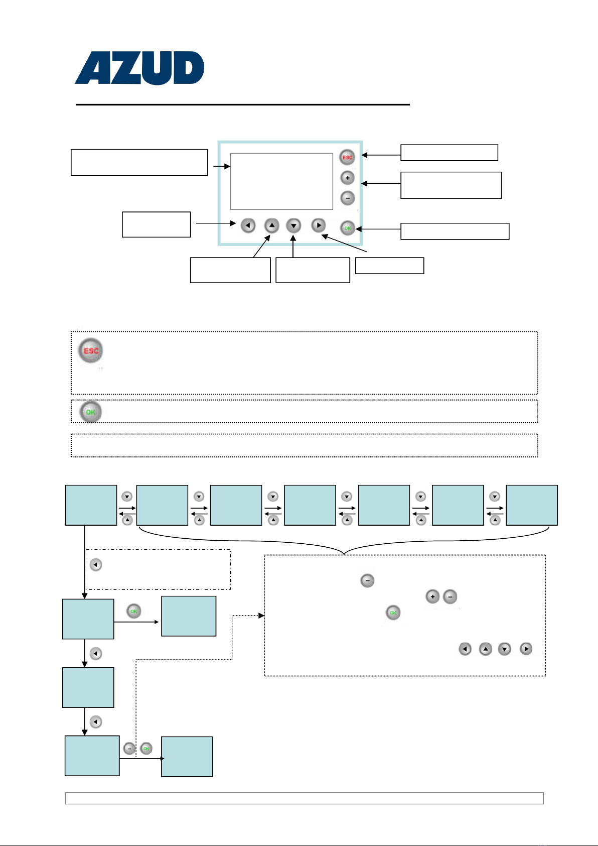
Electronic control system. Integrated controller to control all the detection and activation functions. It is
assembled on an electric cabinet with degree of protection IP 55.
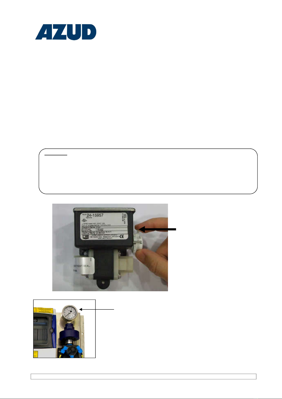
Detection system. Easy reading differential pressure gauge.
Activation system. 24 V NC three-way electrovalves
All these is completely assembled and contains the auxiliary elements which complete the electric and
hydraulic system and which turns the Control Unit into an independent and automatic system.
2.1 Introduction.
1. Introduction
2. Characteristics of the Control Unit.
2.2. Identification of the product.
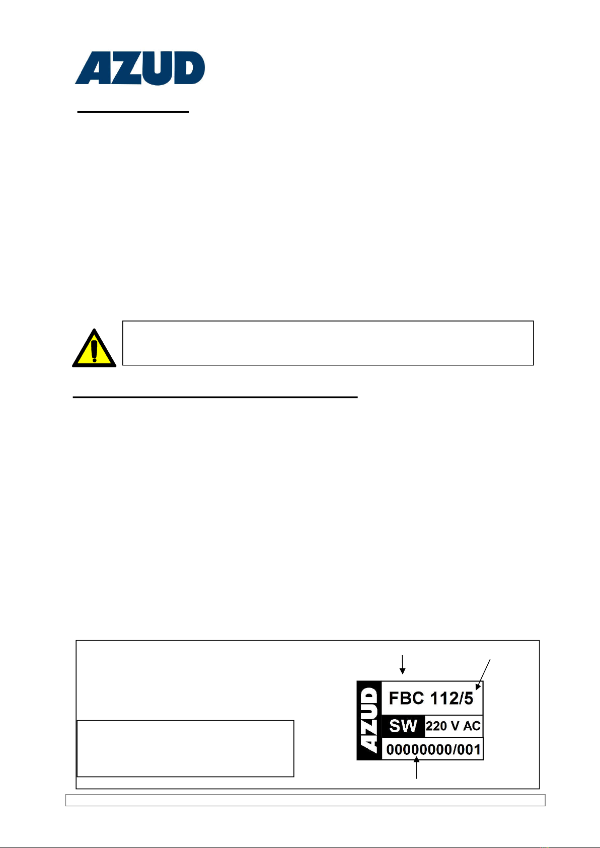
In AZUD we identify each Control Unit with an industrial label with a unique serial number. The
factory identifies the different control units with these labels.
The modification or elimination of the
label cancels any warranty; and so
impedes the identification of the
Equipment.
The industrial label indicates: the model of
the equipment, the number of stations, the
year of manufacture and the serial
number.
NUMBER OF STATIONS
SERIAL NUMBER
MODEL
Thank you very much for your confidence in AZUD FBC control units to solve your Filtration
Equipments Automation needs. Please, read carefully this manual and you will find the answer to most
of your questions.
However, IF YOU HAVE ANY DOUBT OR NEED ADDITIONAL INFORMATION, PLEASE CONTACT
All the control units manufactured in SISTEMA AZUD, S.A are subject to strict quality control tests and
are manufactured under a productive process which meets the requirements of the standard ISO
9001/2000.
Sistema AZUD is also committed with the environment, and is certified under the Environmental
Management System of the standard ISO 14001.
This Manual contains some instructions and warnings which should be observed
to obtain a correct installation, operation and subsequent maintenance of the
Control Unit.

Water Filtration Solutions
4
1- By interval of working time of the installation.
2- By differential of pressure.
3- By external or remote signal.
4- Manually.
A backflushing cycle will be activated each time the programming time passes.
A backflushing cycle will be activated each time there is a differential of
pressure in the equipment equal or higher than the regulated in the
Differential Pressure Gauge, and after the confirmation time of the pressure
gauge programmed in the FBC.
A backflush will be activated when sending a contact free of tension to the corresponding input
of the FBC trough an external or remote signal.
OK
2.4 Types of activation and backflushing cycles.
You can activate a backflushing cycle manually, through the
keyboard of your Control Unit. The backflush will be activated when
you keep pressed for some seconds the key OK.
AZUD FBC Control Unit will allow to keep all this options at the same time, or select just some of
them.
2.3 Technical Data AZUD FBC Control Unit.
Do not connect AZUD FBC Control Unit in installations fed by a power
generator. The variations in voltage could damage it.
VOLTAGE 220 V AC
CONSUMPTION 0.5 A
OUTPUT FUSE 2 A 24 V
5 x 20 mm
FEEDING FUSE 0.5 A 220 V
5 x 20 mm
SOLENOIDS
OUTPUT CONSUMPTION MAXIMUM 1 A
ADMISSIBLE TEMP. 5 – 50ºC
OUTPUTS INPUTS
103 112 103 112
NUMBER 4 13 4 4
TYPE VOLTAGE CONTACT FREE OF
VOLTAGE

Water Filtration Solutions
5
Working Description:
• The start of the sequential self-cleaning process is made when the Control Unit activates the
backflushing cycle under one of the four possible orders: existing differential of pressure, attending to
the frequency of irrigation, by direct actuation on the keyboard or by external signal.
The programmer which integrates the Control Unit, activates the electric contact which supplies
voltage to the NC solenoid, in charge of activating the first station that makes the self-cleaning
process; transforming the electric signal in a hydraulic signal in charge of feeding the chamber of the
3-ways valve.
Through the feeding of the chamber of the 3-ways valve it is made a movement of the internal piston
which closes the entrance of water to the filter and communicates the interior of the filter with the
drainage manifold. This allows the filtered water from the rest of filter from the outlet manifold,
introduces to the filter in the opposite way from the filtration direction, activating the self-cleaning
mechanism of DF-DISC filtration discs.
The deactivation of the solenoid from station n.1 allows the 3-ways valve come back to the resting
position and the filter to the filtration process.
Once the station n.1 has finished the backflushing process, this is repeated sequentially until finishing
all the stations in the filtration equipment.
The end of the self-cleaning process coincides with the closure of the drainage outlet and the opening
of the inlet to the filter from the inlet manifold, being re-established the initial filtration conditions.
2.5.- Working Description.
AZUD FBC Control Unit integrates all the control, detection and operation elements that allow AZUD
HELIX AUTOMATIC filtration equipment to have complete autonomy. All the components are supplied
already assembled, with the auxiliary elements that complete the electric and neumatic system, which
turn the Control Unit into an autonomous and automatic system.
The electronic control system and the electric auxiliary elements are placed in a water-tightness housing,
completely isolated from the hydraulic components.

Water Filtration Solutions
6
The key allows the access from any screen to the main screen.
Press the key before making consult or modification in the programming values.
The numeric values in red are can be changed by the user.
Keep pressed to activated manually a whole backflushing cycle.
Press to stop the backflushing process.
SCREEN: AZUD FBC has a four
lines screen
Left arrow:
Utilities
Right ArrowUp arrow: Screens
backward
Down arrow:
screen advance
AZUD
11:08
OK: Confirmation
Data advance and
backward
ESC= Exit
3.1. Control Unit Site Map
3. Programming of AZUD FBC Control Unit.
AZUD
00:00
ADVANCE
MASTER
VALVE
0:00
BACKFLUSHING
TIME
STATIONS
15 seg
TIME
BETWEEN
STATIONS
15 seg
BACFLUSHING
BY TIME
15 seg
DELAY
START
PD
15 seg
NUMBER
OF
STATIONS
8
TOTAL
SUMMATOR
7
PARTIAL
SUMMATOR
0
OK = BORRAR
TOTAL
BACKFLUSHIG
89
Set hour
dd/mm/yyy
14/05/2010
16:10 Jue
Acces to UTILITIES SCREEN:
Keep pressed
If the screen has more than a numeric value to
modify we can select it with the direction keys
To modify the numeric value in the screen
- Press the key
- Increase / decrease the numeric value
- Validation of the new value
CLOCK
ADJUSTEMENT
16:10

Water Filtration Solutions
7
Following the different parameters to be programmed of your Control Unit will be introduced. AZUD FBC
incorporates a standard programming which allow the user to start up the filtration equipment by the first
time and being familiar with the programming to be adapted to the particular conditions of your
installation.
Anticipation time of the signal of the sustaining electrovalve, which allows this to reach its regulation of
pressure before starting the backflushing cycle.
If your equipment does not have this option press time 0 sec.
3.2 Anticipation time of the sustaining valve.
Time that remains active each one of the filtration stations which made the filtration system. The
programmed time is the same for all the stations. During one cycle of activations it is made sequentially
one activation for each station the system has programmed.
3.3 Backflushing time of each one of the stations.
Time that passes from the stop of the actuation of one filtration station and the start on the activation of the
following.
During this time the system deactivates all the outlets active (general outlet).
3.4 Time between stations.
3.5 Time between backflushing stages.
Minimal frequency to make the activation of a backflushing cycle, always the system in active filtration
process.
3.6 Delay of the differential pressure gauge.
It is defined as the necessary time in which the contact must be closed in a continuous way in the
corresponding inlet of the differential pressure gauge for one activation order to be effective and the
backflushing cycle is activated. This is a performance especially indicated to avoid unnecessary
backflushings provoked by the start of the filling of the installation. (Start-up of the installation).
Select the number of stations of your filtration equipment.
3.7 Number of Stations of the Filtration Equipment

Water Filtration Solutions
8
The differential pressure you should regulate in your differential pressure gauge should be between 0,2
– 0,3 bar over the pressure with the maximum flow of your system, when the filters are clean.
3.8 Adjustment of the different types of differential pressure gauges.
Azud FBC Control Units include a differential pressure gauge which indicates the differential pressure
existing in the installation and provides us with a free-tension contact once the pre-established
differential pressure is exceeded. The differential pressure reading is carried out through two P1 and P2
inlets (see hydraulic linkages), which are collected in the inlet and outlet manifold respectively.
The differential pressure value in an equipment's inlet and outlet is not the same in all the installations.
So you must regulate the differential pressure value which will activate a backflushing cycle in the
equipment. The Control Unit has been calibrated at 0.6 Bar by the factory. You must regulate this value
according to the installation conditions.
EXAMPLE
ARECENTLY INSTALLED SYSTEM which working with a
MAXIMUM FLOW, has a 0,1 bar DIFFERENCE of pressure
The recommended value is 0,3 - 0,4 bar.
Adjust the differential pressure
gauge turning the selector of the
differential of pressure.
Manometer to visualize the pressure

Water Filtration Solutions
9
If you want to backflush by remote control,
using any other mechanism…
Connect to the input nº 3 and to the common
the external sign.
1 2 3
INPUTS
INPUTS
4
COMMON
INLETS
4. Auxiliary Elements
4.1. How to activate backflushes by external signal
Connect one of the outlets to input 4
and the other to the common.
To cancel the backflushes
connect input 4 with the
common (by means of a jumper)
1 2 3
INPUTS
INPUTS
4
COMMON
INLETS 1 2 3
INPUTS
INPUTS
4
COMMON
INLETS
If you wish to temporarily cancel backflushes while any
equipment or installation element are operating:
4.2. How to connect an element which temporally cancels the backflushes
This signal can be used for the connection of any element which needs to be activated in advance
and during the backflushing cycle.
4.3. Anticipation signal. Sustaining valve.
OUTOUTOUT 1 2 3 4
COMMON
OUTPUTS
FBC 103
OUTOUTOUTOUT 1 2 3 4 5 6 7 8
COMMON
OUTPUTS
9
E 0 2
E 0 4
E 0 1
E 0 2
FBC 112
This option can be used to the installation of a Pressure Sustaining Valve.
AZUD HELIX AUTOMATIC Equipment needs to guarantee a minimal pressure during the backflushing
of the stations. If your installation does not fulfil this requirement, AZUD can supply an adequate
Sustaining Valve to your installation.
-MOBILE PHONE
- PC
-SIMPLE PUSH-BUTTON
- ....

Water Filtration Solutions
10
HYDRAULIC OPERATION OF THE SUSTAINING VALVE.
The sustaining valve activation allows to regulate the upstream pressure according to the pilot
regulation.
adjusting screw of
upstream pressure
Screw: increase pressure
Unscrew: decrease pressure
Recommended
pressure according to
the Equipment's
Technical Data
The sustaining valve is an OPTIONAL component of the equipment
1 2 3
INPUTS
INPUTS
4
COMMON
INPUTS
AZUD RECOMMENDS TO HAVE ALWAYS ACTIVATED THE BACKFLUSHING BY
TIME
If you want AZUD FBC Control Unit to time, it must exist a free-tension contact
in the electrical connections, common and input 1 (See electrical connections)
AZUD supplies the control unit with an electric cable bridge joining the
electrical connections. In this way, if backflushes are selected by time, the
backflush cycle is activated once the programmed time is finished.
The time counted is time of equipment electrically feeding.
If you want the real time of filtered water counts it will be used the contact of the auxiliary relay of
the pump or any other device that detects the flow of water (differential pressure gauge, etc). This
would be the option recommended by AZUD.
Such contact will be connected to the common-input 1 counted in this way tje real operation time of
the equipment.
4.4 How to activate the backflushings by real filtration time?
Option 1: Activate backflushes once passed real time.
Option 2: Activate backflushings passed real operation time.

Water Filtration Solutions
11
In LP configuration equipments, it is essential that the Control Unit counts the real time of water
filtration. If this not so, it could happen that the backflushing pump connect itself (when a backflush by
time is activated) with the equipment non-operating. This could cause catastrophic effects on the
backflushing pump.
For the Control Unit to count the real time of water filtration, you should connect the One Signal
Pressure Gauge in this inlet. In this way, you will make sure that backflushes by time are not made
when there is not water pressure in the Filtration Equipment.
The One Signal Pressure Gauge closes the contact while the pressure exceeds the regulated value in
the RANGE scale and until the pressure reaches the resulting value of the subtraction between the
RANGE scale value and the regulated value in the DIFF scale. So, while the pressure is between these
two values, the Control Unit counts the time for the Backflushes by Time activation (Figure 1).
When the pressure drops below the resulting value of the subtraction between the RANGE scale value
and the DIFF scale value, the pressure gauge opens the contact. This is when the Control Unit stops
counting time.
Fig. 1. Filtration equipment running. In this case, the
pressure conditions take place to close the contact.
The Control Unit counts the time. The activation of
backflushes by time is possible.
Fig. 2. Filtration equipment switched off. In this case,
pressure conditions does not take place to close the
contact. The Control Unit does not count time. The
activation of a backflushing cycle is not possible,
preventing the starting of the backflushing pump in
these conditions.
1 2 3
INPUTS
INPUTS
4
COMMON
INPUTS
2
4
1
One signal
pressure gauge
contacts
1 2 3
INPUTS
INPUTS
4
COMMON
INPUTS
2
4
1
One signal
pressure gauge
contacts
The pressure values of the DIFF and RANGE scales are regulated with the two upper screws of the
pressure gauge shown in the picture.
DIFF
RANGE
The pressure gauge is regulated with 1Bar pressure in the
RANGE scale and 0.7 Bar in the DIFF scale in the factory. The
Control Unit begins to count time with this values when the
Filtration Equipment exceeds 1 Bar and the pressure descends
to 1-0.7 = 0.3 Bar, when switching off the equipment.
Connection of pressure gauge of one signal to activate backflushing when the
real working time passes.

Water Filtration Solutions
12
COMPONENTS CONTROL UNIT AZUD FBC
NUMBER CODE DESCRIPTION MATERIAL
1 -------- PROGRAMMER --------
2 -------- DIFF. PRESSURE GAUGE --------
3 -------- CONTROL UNIT PANEL --------
4 ------- PRESSURE REGULATOR ----
5 ------- ELECTROVALVES --------
6 -------- PRESSURE SELECTOR WITH MANOMETER --------
5. Components and spare parts.
Please indicate the serial number of the Control Unit to the request of spare parts.
NOTE: THE SPARES ARE THE COMPONENTS WITH A CODE.
TO THE REQUEST OF OTHER COMPONENTS ASK YOUR DISTRIBUTOR.
5
4
3
2
1
6

Water Filtration Solutions
13

Water Filtration Solutions
14
Preserve this manual so that the user of the Equipment could familiarize with it. Below there are some
general instructions for a safe operation of the Equipment. These instructions are not a close list, the
user must adopt as many security measures as necessary to guarantee his security. In this way, this
safety information does not substitute the accident emergency measures which should be adopted.
Any additional requirement or change in its use could cause damages not covered by the
warranty.
6. Safety Information
-The transmission of electric current to the human body could cause serious
burns and even death.
-Take all the necessary precautions to avoid electric discharges and damages on
people, goods and the equipment.
-The electrical installation should be carried out by a qualified electrician.
-Do use insulating clothing, authorized safety equipments and tools which insulate
the electrical current.
-Do never take away the electrical protection.
-Do not touch the Control Unit with wet hands
-Do not put your hands in the electric boards, circuits ... There is a risk of
electrocution.
-An independent earth connection for the equipment should be provided.
-The equipment´s installation should be carried out only by qualified staff.
-A 6A magneto-thermal switch and a 16 A differential should be installed as a cut-out
switch, close and accessible to the user.
-The equipment should have its own supply.
-The equipment´s feeding should be directly taken from the main switch, avoiding the
connection of any other electric device in/to the same feed-line of the equipment. It is
recommended the 1.5 mm2H05VV-F3G cable for its connection to the mains.
-As far as possible, set the power circuits away from the electrical machines.
-If the inductive circuits, as well as the contactor ones, electrovalves, etc, are installed
next to the system, it is essential not to parasite your bobbin with RC filters.
-The fluctuations of the net are acceptable just up to the indicated tolerances (±5 %).
-Do not connect control circuits (relays, contactors) to the connection terminals of the
system to the net.
-Avoid electromagnetic interferences. This kind of interferences are due mainly to:
electric engines, transformation centres, cables of electric energy transmission, power
contactors and any other electrical power mechanism without the proper electromagnetic
insulation.

Water Filtration Solutions
15
7. Installation Instructions.
To assemble the Control Unit support, place the plate tube on the support, and adjust it with
fixation screws. To Fix the support to the ground, use adequate sleeper screws depending on the
type of ground for the fixing of the support on the ground.
7.1 installation of the Support
7.2 Neumatic connection of the Control Unit with the Filtration Equipment.
The linkage is carried out due to the junction of each of the command microtubes of the Control Unit
with its Filtration Equipment homologous
The nomenclature used is the following:
* GLOSSARY
STATION
We understand by station each of the groups of filters which backflush
altogether in the same signal of the Control Unit. A station can be formed by one
or several filters.
DIFFERENTIAL
PRESSURE
GAUGE
It indicates the stipulated value through which it is established the contact for the
activation of a backflush.
COMMAND DESCRIPTION: use and connection
T
PRESSURE TAP: For the feeding of all the command circuit. It must match with the
maximum pressure point of all the installation, which usually is the inlet manifold ( it
feeds from the auxiliary filter). You can also connect the pressure intake circuit with a
pneumatic pressure line which has a pressure greater that the one at the inlet of the
filters.
D
ESCAPE:Command to the evacuation of the air from the electrovalves chambers. It
evacuates the air placed in the chamber of the valve at the instant in which the
activation of the station* or corresponding filter stops.
It ALWAYS has to be in contact with the atmosphere.
P1
Pressure tap in inlet manifold, to be connected to the differential pressure gauge*.
There is an intake in the inlet manifold with a ¼” filter + a 1/8” male elbow to connect
the command.
P2
Pressure tap in outlet manifold, to be connected to the pressure differential
gauge*. There is an intake in the outlet manifold with a ¼” filter + a 1/8” male elbow to
connect the command.
E1
Station 1: Command in charge of the feeding of the hydraulic relay and/ or the three-
way valve chamber for the activation of the station or nº1 filter backflushing process,
and its drainage from the moment in which the nº1 electrovalve activation stops.
E2
Station 2: Command in charge of the feeding of the hydraulic relay and/ or the three-
way valve chamber for the activation of the station or nº2 filter backflushing process,
and its drainage from the moment in which the nº2 electrovalve activation stops
E3 ... In ...

Water Filtration Solutions
16
7.3 Pneumatic connection between the Control Unit and the pressurized air
equipment.
Connect the intake source of air to the control Unit. To make this connection we leave in the
pressure regulator a 12 elbow of quick coupling.
INTAKE OF AIR “T” TO
THE CONTROL UNIT
This control unit has a needle valve to
adjust the inlet pressure of the two
stations grouping. This device is adjusted
from the factory.
- To the correct working of the equipment it should have a minimum
of 6 bar to 1200 l/min in the backflushing process.
- The maximum pressure of air intake should not surpass the 7 bar.
To adjust the inlet pressure of the air intake it should be taken into account the inlet pressure
of water in the filtration equipment. The maximum pressure of air intake should be equal to the
maximum inlet pressure of water to the filtration equipment plus 1 bar.
Air intake P = inlet water P + 1bar
It is not necessary the use of lubrication in the air treatment of the pneumatic command. It can
even damage some components.
The instructions and warnings should be taken into account in order to obtain a correct
installation, working and post-working of the Equipment.
Not obeying the instructions or warning can cause damages or failure in the working of the
equipment.

Water Filtration Solutions
17
8. Electric Circuits.
ELECTRIC CONNECTION INSTALLED ON THE CONTROL UNIT FBC 103 IN THE FACTORY FOR A 220 V AC EQUIPMENT
EN 60617 ESP
+ - B 1 2 3 4 5 6 7 8 9 10 11 12 13 14 15
230VAC
230V
TRAFO
SALIDA
OUTPUT -24V
ENTRADA
INPUT-230V
24V
TRAFO -+
E3 E2 E1E4 COM COM
DP
230VAC
AUTOMATA/AUTOMATON AL-24MR-D
ENTRADAS DIGITALES
DIGITAL INPUTS
CABLEADO/WIRING 6X0.25 mm
24VDC
24VDC
SALIDA/OUTPUT
24VAC
0.5A
2A
AUTOMATA/AUTOMATON AL-24MR-D
SALIDAS DIGITALES
DIGITAL OUTPUTS
OUT 1 OUT 2 OUT 3 OUT 4
24VAC
0V
F1 F2
TR
ROJO/MARRON
RED/BROWN
AZUL/BLUE
NEGRO/BLACK
VERDE/GREEN
AMARILLO/YELLOW
BLANCO/WHITE
2
EV1
1
2
EV2
1
2
EV3
1
AZUL/BLUE
AZUL/BLUE
AZUL/BLUE
AZUL/BLUE
MARRON
BROWN
LEYENDA/MAP KEY
Fusible/Fuse
TR Transformador/Transformer
Presostato diferencial
Differential pressure
2
EV1
1
Electrovalvula/Electrovalve
DP
2
EVS
1
EXTERNO AL EQUIPO
EXTERNAL TO EQUIPAMENT
VALVULA SOSTENEDORA
SUSTAINING VALVE
RED/POWER SUPPLY

Water Filtration Solutions
18
220 V AC AZUD FBC-103 CONTROLLER GRAPHIC FRAME
COMMON INPUTS
INPUTS FUNCTION TYPE
1 TIME SIGNAL METER
ACTIVATION CONTACT
2 DIFFERENTIAL PRESSURE GAUGE BACKFLUSH CONTACT
3 EXTERNAL SIGNAL BACKFLUSH CONTACT
4TEMPORARY CANCELLATION OF
BACKFLUSHES
STOP
BACKFLUSHES
OPTIONAL
CONTACT
COMMON
OUTPUTS
OUTPUTS FUNCTION TYPE
1 STATION Nº 1 BACKFLUSH 24 V AC TENSION
2 STATION Nº 2 BACKFLUSH 24 V AC TENSION
3 STATION Nº 3 BACKFLUSH 24 V AC TENSION
4 ANTICIPATION SIGNAL BACKFLUSH 24 V AC TENSION
OUTPUTS FUSE 5x20 2 A 24 V
NETWORK CONNECTION FEEDING 220 V AC
FEEDING FUSE 5x20 0.5 A 220 V AC
OUTPUTS INPUTS
OUTPUTS
FUSE
FEEDING FUSE
OUT
OUTOUTOUTOUT 1 2 3 4 5 6 8 9
RED
220 AC COMUN
ENTRADAS 1 2 3 4
ENTRADAS
COMUN
SALIDAS 7

Water Filtration Solutions
19
EN 60617 ESP
ELECTRIC CONNECTION INSTALLED ON THE CONTROL UNIT FBC 112 IN THE FACTORY FOR A 220 V AC EQUIPMENT
+ - B1 2 3 4 5 678 9 10 11 12 13 14 15
230VAC
230V
TRAFO
SALIDA
OUTPUT-24V
ENTRADA
INPUT-230V
24V
TRAFO -+
E3 E2 E1E4 COM COM
DP
230VAC
AUTOMATA/AUTOMATON AL-24MR-D
ENTRADAS DIGITALES
DIGITAL INPUTS
CABLEADO/WIRING 6X0.25 mm
24VDC
24VDC
SALIDA/OUTPUT
24VAC
0.5A
2A
AUTOMATA/AUTOMATON AL-24MR-D
SALIDAS DIGITALES
DIGITAL OUTPUTS
OUT 1 OUT 2 OUT 3 OUT 4 OUT 6 OUT 7 OUT 8 OUT 9OUT 5
24VAC
0V
EO1 EO2 EO3 EO4
F1 F2
TR
ROJO/MARRON
RED/BROWN
AZUL/BLUE
NEGRO/BLACK
VERDE/GREEN
AMARILLO/YELLOW
BLANCO/WHITE
2
EV1
1
2
EV2
1
2
EV3
1
2
EV4
1
2
EV5
1
2
EV6
1
2
EV7
1
2
EV8
1
2
EV9
1
2
EV10
1
2
EV11
1
2
EV12
1
AZUL/BLUE
AZUL/BLUE
AZUL/BLUE
AZUL/BLUE
AZUL/BLUE
AZUL/BLUE
AZUL/BLUE
AZUL/BLUE
AZUL/BLUE
AZUL/BLUE
AZUL/BLUE
AZUL/BLUE
AZUL/BLUE
MARRON
BROWN
LEYENDA/MAP KEY
Fusible/Fuse
TR Transformador/Transformer
Presostato diferencial
Differential pressure
2
EV1
1
Electrovalvula/Electrovalve
EXTERNO AL EQUIPO
EXTERNAL TO EQUIPAMENT
DP
2
EVS
1
VALVULA SOSTENEDORA
SUSTAINING VALVE
RED/POWER SUPPLY
This manual suits for next models
1
Table of contents
Other AZUD Water Filtration System manuals
Popular Water Filtration System manuals by other brands

Vestergaard
Vestergaard LifeStraw Mission user manual

PREMIER TECH
PREMIER TECH ECOFLO owner's manual

Canature WaterGroup
Canature WaterGroup 89 Dual Media Tank owner's manual

Clack Valves
Clack Valves WS1 Installation, operation & maintenance manual

PISCO
PISCO VFL360-10-2-3 quick start guide

Halsted Rain
Halsted Rain Frogmouth Filter installation instructions