Water Filtration Solutions
10
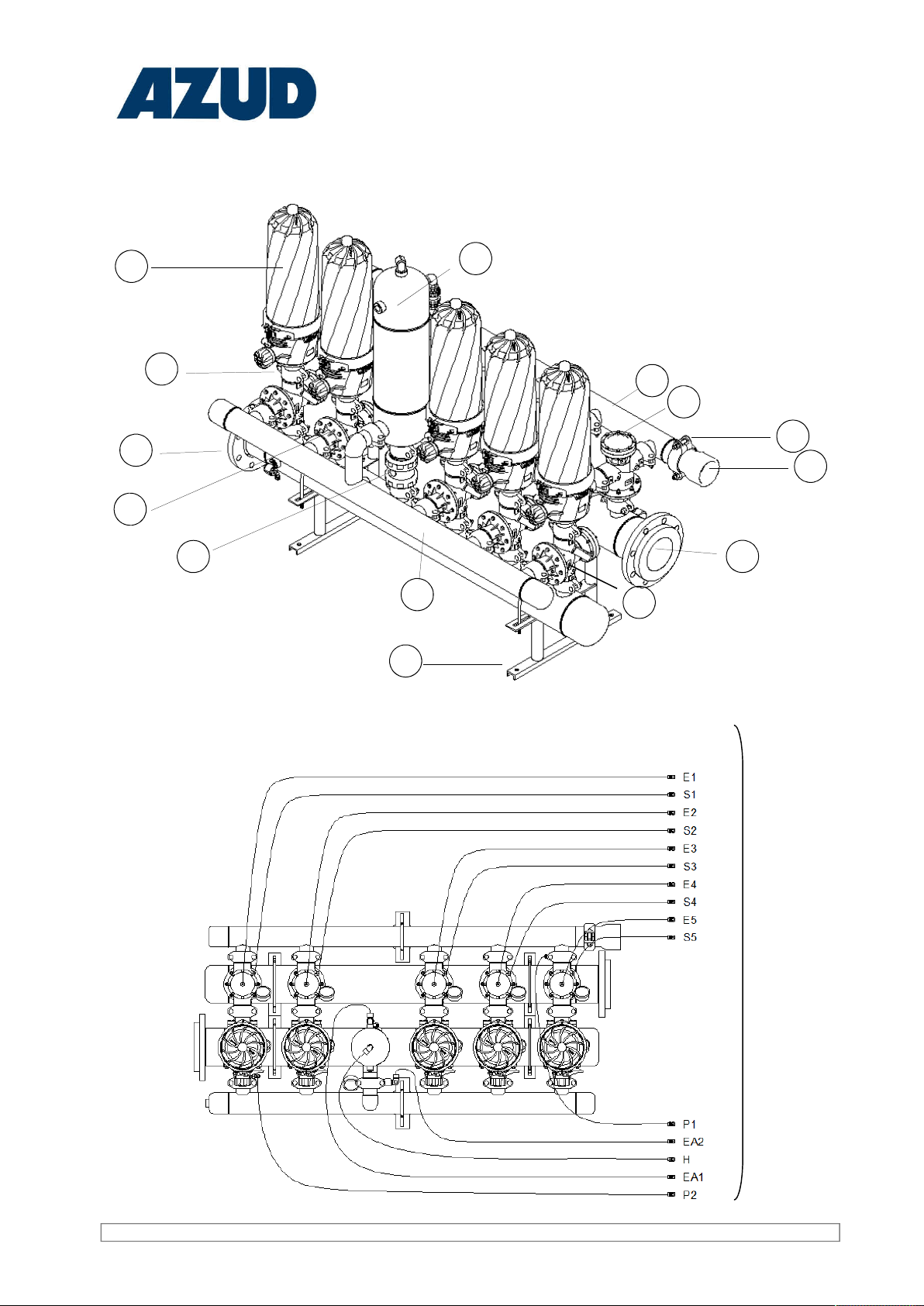
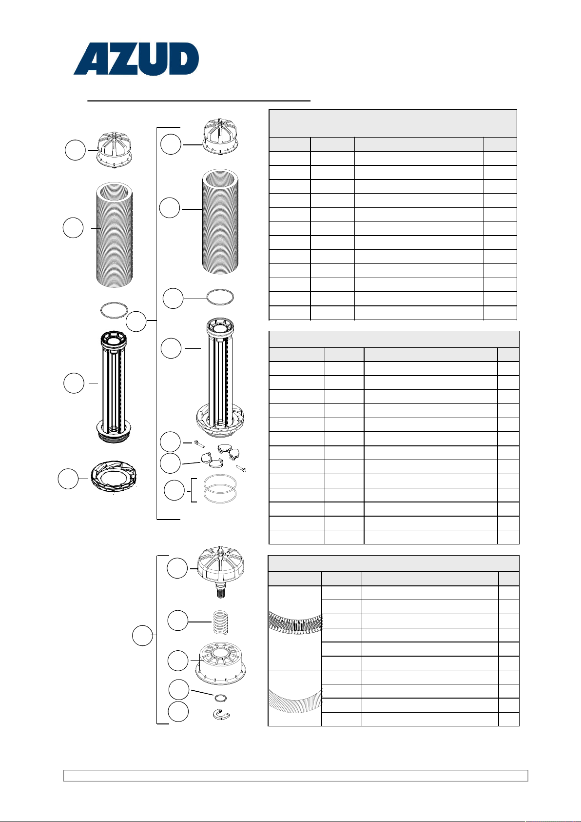
FILTERING ELEMENT SPARE PARTS
NUMBER CODE DESCRIPTION un
21 PISTON FRAME AZUD HELIX AUTOMATIC 1
22 --- DISCS KIT AZUD HELIX AUTOMATIC 1
23 18R60037 PISTON OGASKET92,6 x 100 x 4 mm 1
24 ---------- FRAME WIITHOUT CHECK VALVE 1
25 ---------- CHECK VALVE 1
26 ---------- STEM CLAPETA 1
27 18R60026 O-RING 103X4 2
28 ---------- A PISTON COMPONENT 1
29 ---------- SPRING 1
30 ---------- B PISTON COMPONENT 1
31 ---------- O-RING 13X2 2
32 ---------- CLIP 1
AZUD HELIX AUTOMATIC FILTERING ELEMENT
SPARE PARTS KITS
NUMBER CODE DESCRIPTION un
23-27x2-31-32 18R60116 O-RINGS KIT AUTOMATIC FILTER 3.0 1
23-31-32 18R60117 PISTON SET OF O-RINGS AUTOMATIC FILTER 3.0 1
23-27x2-29-31-32 18R60118 MAINTENANCE KIT AUTOMATIC FILTER 3.0 1
20 18R60119 FRAME AUTOMATIC FILTER DEP 3.0 1
25x2-26x2 18R60120 CHECK VALVE AUTOMATIC FILTER 3.0 1
26 ---------- STEM CLAPETA 1
27 18R60026 O RING 103X4 2
28 ---------- A PISTON COMPONENT 1
29 ---------- SPRING 1
30 ---------- B PISTON COMPONENT 1
31 ---------- O RING 13X2 2
32 ---------- CLIP 1
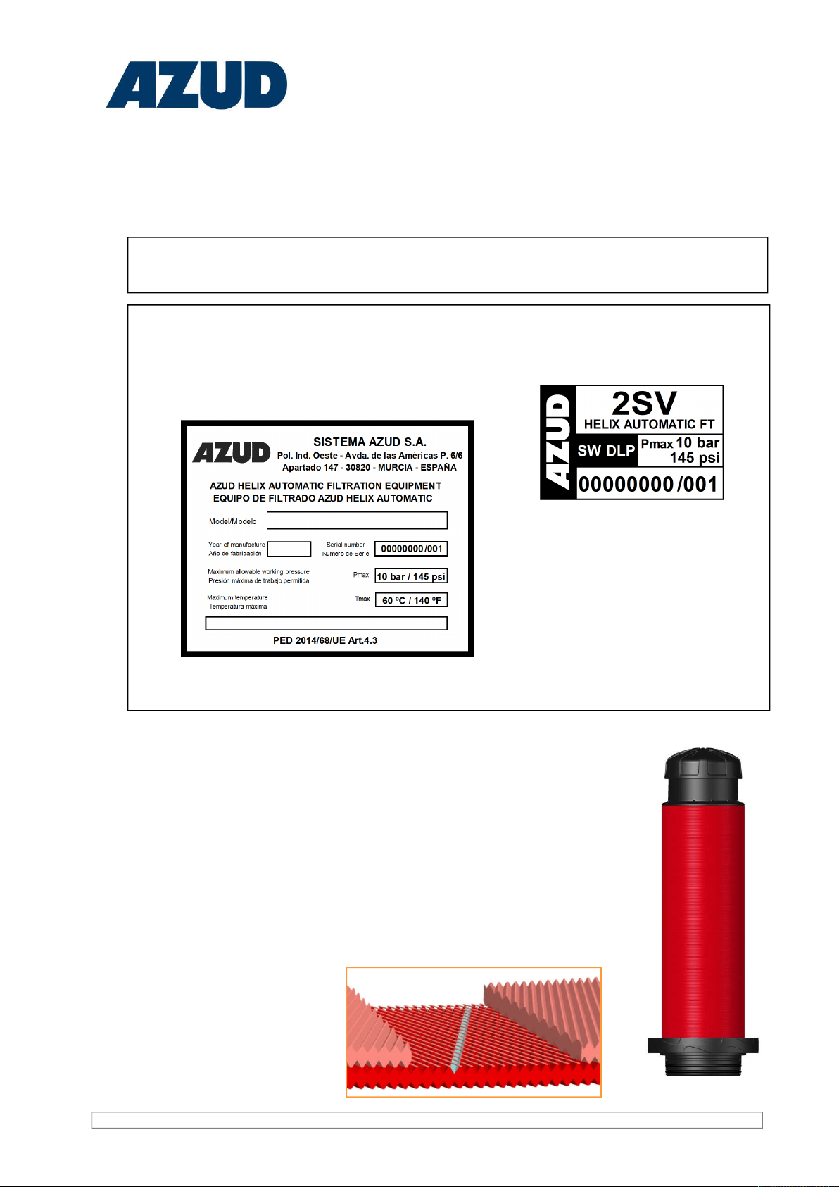
33 17RXP020 HELICAL ELEMENT 1
AZUD HELIX AUTOMATIC DISCS KIT
NUMBER CODE DESCRIPTION un
22
18R60033 S-DISC KIT AUTOMATIC FILTER 130 MICRON 1
18R60039 S-DISC KIT AUTOMATIC FILTER 100 MICRON 1
18R60034 S-DISC KIT AUTOMATIC FILTER 50 MICRON 1
18R60035 S-DISC KIT AUTOMATIC FILTER 20 MICRON 1
18R60038 S-DISC KIT AUTOMATIC FILTER 10 MICRON 1
18R60036 S-DISC KIT AUTOMATIC FILTER 5 MICRON 1
22
18R60040 DISC KIT AUTOMATIC FILTER 400 MICRON 1
18R60012 DISC KIT AUTOMATIC FILTER 200 MICRON 1
18R60011 DISC KIT AUTOMATIC FILTER 130 MICRON 1
18R60010 DISC KIT AUTOMATIC FILTER 100 MICRON 1
28
29
30
32
31
21
21
22
23
24
25
26
27
17
21
22
20
33