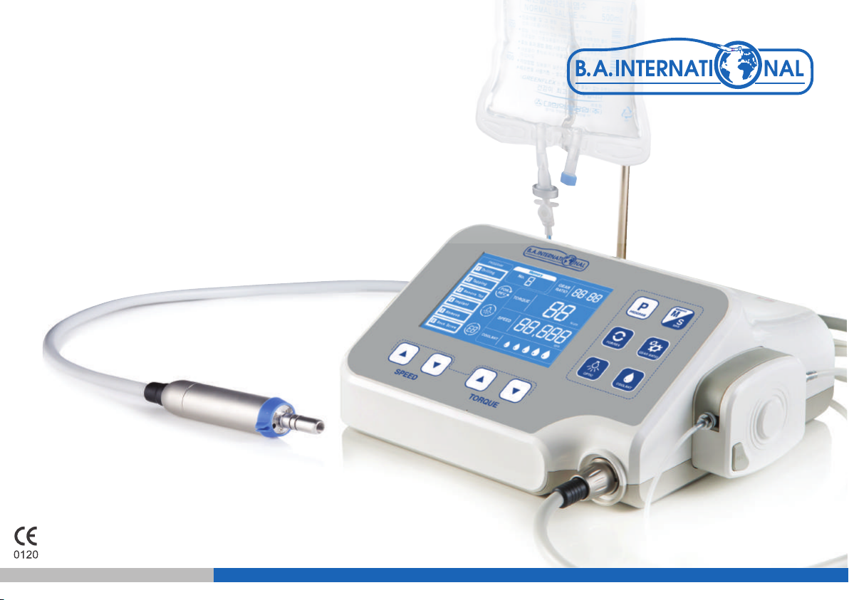
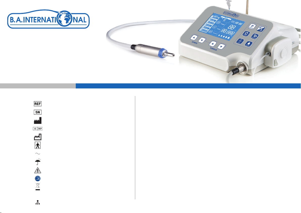
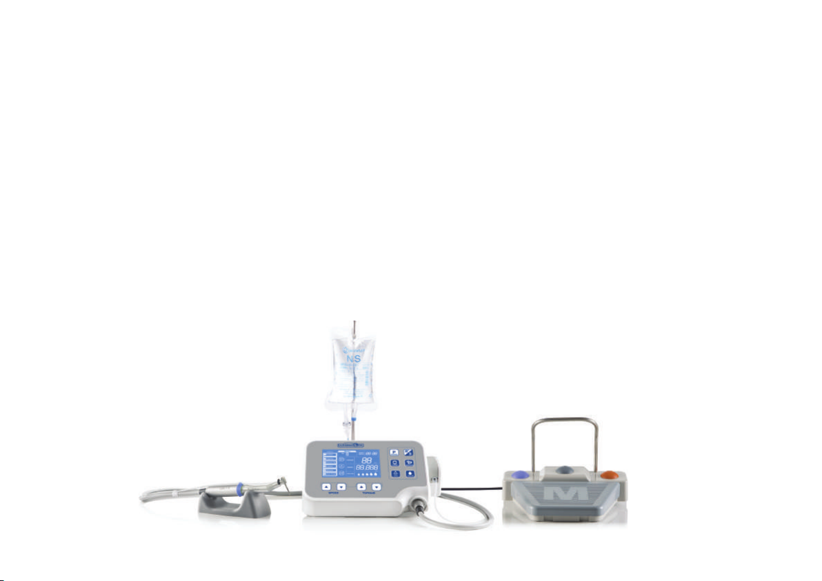
B.A. International Optima OS600L User manual
Other B.A. International Dental Equipment manuals

B.A. International
B.A. International OPTIMA BAC100 User manual

B.A. International
B.A. International Optima E+ User manual

B.A. International
B.A. International BA 45 User manual

B.A. International
B.A. International Powersurge User manual

B.A. International
B.A. International Optima BA60E User manual

B.A. International
B.A. International Ultimate 1400 User manual

B.A. International
B.A. International BA-OPTIMA 10 User manual

B.A. International
B.A. International BA-OPTIMA 10 User manual

B.A. International
B.A. International Ultimate BASE280 User manual

B.A. International
B.A. International BA Ultimate LED User manual

B.A. International
B.A. International Ultimate BA-603 User manual

B.A. International
B.A. International BA-Optima BA121T User manual

B.A. International
B.A. International BA604E User manual

B.A. International
B.A. International BA OPTIMA E+ BAE380R User manual

B.A. International
B.A. International BA Ultimate LED User manual

B.A. International
B.A. International BA OPTIMA BA65E User manual

B.A. International
B.A. International BA Optima User manual

B.A. International
B.A. International Ultimate BA-102 User manual

B.A. International
B.A. International BA ULTIMATE 695 User manual

B.A. International
B.A. International OPTIMA BA520FM User manual
Popular Dental Equipment manuals by other brands

Vatech
Vatech EzRay Air VEX-P300 user manual

KaVo
KaVo GENTLEpower LUX Contra-angle 25 LP Technician's Instructions

DENTSPLY
DENTSPLY SmartLite Focus Instructions for use

LM
LM ProPower CombiLED quick guide

Owandy Radiology
Owandy Radiology RX-AC user manual

mectron
mectron Piezosurgery Cleaning and sterilization manual