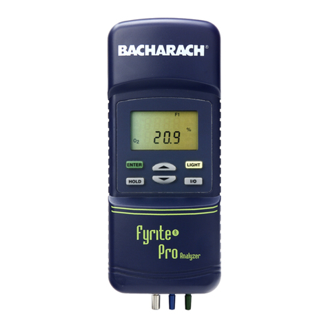
Pur•Chek™Pro
Instruction 2100-9001 1
1 Introduction
1.1 How to Use This Manual
This manual provides important information on how to operate and maintain Bacharach’s Pur•Chek™ Pro HVAC
Diagnostic Refrigerant Analyzer.
To assure operator safety and proper use of the Pur•Chek™ Pro, please read, understand, and follow the con-
tents of this manual.
1.2 Warnings & Cautions
When used in this manual or as labeled on the Pur•Chek™ Pro, the following hazard symbols and/or associ-
ated words are defined as follows:
WARNING: This symbol and/or the use of the word WARNING indicates a potential hazard
associated with the use of this equipment. It calls attention to a procedure, practice, condition,
or the like, which if not correctly performed or adhered to, could result in death or serious injury.
WARNING: This symbol and/or the use of the word WARNING indicates a potential hazard
from electrical shock. It calls attention to a procedure, practice, condition, or the like, which if
not correctly performed or adhered to, could result in death or serious injury.
CAUTION: This symbol and/or the use of the word CAUTION indicates a potential hazard
associated with the use of this equipment. It calls attention to a procedure, practice, condition,
or the like, which if not correctly performed or adhered to, could result in minor or moderate
injury.
IMPORTANT: The use of the word IMPORTANT in this manual calls attention to a procedure,
practice, condition, or the like, which if not correctly performed or adhered to, could result in
incorrect performance of or damage to the equipment and may void the warranty.
1.2.1 Analyzer Warnings
Refrigerant Blend Warning: The HVAC industry is continually introducing new refrigerants.
Many of these new blends can be profiled using the Pur•Chek™ Pro.
Sample Filter Warning: Replace the sample filter of the instrument AS SOON AS RED
SPOTS OR DISCOLORATION BEGIN TOAPPEAR ON THE OUTSIDE DIAMETER OF THE
WHITE ELEMENT. Failure to properly maintain and replace the sample filter will result in
severe damage.
Sample Input Warning: The instrument requires connection of the supplied sample hose to
the LOW SIDE OR VAPOR port of refrigerant storage cylinders or air conditioning systems.
DO NOT attempt to introduce liquid or samples heavily laden with oil into the low side sampling
hose. DO NOT connect the sample hose to the HIGH SIDE or LIQUID port!
Damage caused to the instrument due to the use of the wrong hose on the wrong port will void
the warranty.
Battery Charger Warning: When charging the optional battery with the 1000 mA charger,
the charger will become warm. If the charger becomes hot, unplug the charger immediately!
When charging multiple battery packs, allow the charger to cool between each battery.
