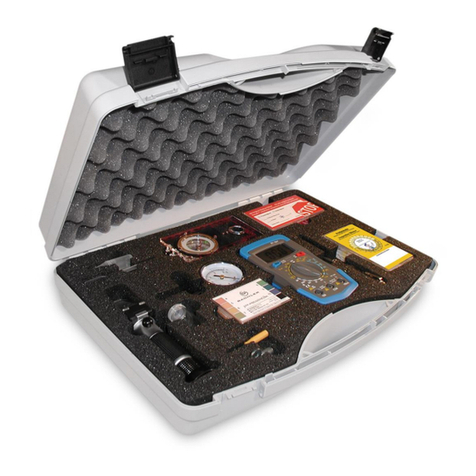
Bachler Solarcheck DT-36T User manual

1
Prüfkoffer für thermische Solaranlagen
Check box for thermal solar systems
Valigetta di prova per i sistemi solari termici
Boîte de contrôle pour les systèmes solaires thermiques
Caja de cheque para las Sistema Solar termales
BESCHREIBUNG DER MESSINSTRUMENTE | DESCRIPTION OF THE
MEASURING INSTRUMENTS | DESCRIZIONE DEGLI STRUMENTI DI MISU-
RA | DESCRIPTION DES INSTRUMENTS DE MESURE | DESCRIPCIÓN DE
LOS INSTRUMENTOS QUE MIDEN

2
Inhalt | Content
DEUTSCH ENGLISH
Pipette
Manometer
destilliertes Wasser
Kompass
Entlüftungsschlüssel
kleiner Schraubenzieher
Handrefraktometer
Prüfglas
Hinweisplaketten (12 Stück)
Prüfplaketten (12 Stück)
Schraubenzieher mit Spannungskontrolle
Digital - Multimeter
pH-Messstreifen (84 Stück)
Pipette
Manometer
destillate water
Compass
Exhaust key
little screwdriver
Refractometer
Measuring glass
Reference plaques (12 pieces)
Inspection plaques (12 pieces)
Screwdriver with tension control
digital circuit analyzer
pH-measuring tapes (84 pieces)
1
2
1
4
22
1
33
44
3
13
5
5
5
6
6
67
7
7
8 8
8
9 9
9
12
11 11
1010
10
12 12
11
1313

3
Deutsch English
Pipette Pipette
Manometer Manometer
Prüfglas Measuring glass
Handrefraktometer Refractometer
Das Handrefraktometer bestimmt den Eisockenpunkt
(Cloud-point) von Wasser-Propylenglykol-, Wasser-
Ethylenglykol- und Wasser- Ethanolgemischen und den
nD20 Brechungsindex von beliebigen Flüssigkeiten.
Messbereiche:
Propylenglykol 0° bis -45°C
Ethylenglykol 0° bis -45°C
Ethanol 0° bis -42° C
nD20 Brechungsindex 1,333 bis 1,400
Die Messung ist zwar weitgehend temperatur-unab-
hängig, jedoch erzielen Sie den exaktesten Wert bei
einer Mediumtemperatur von 20°C.
Der Eisockenpunkt (Cloud-point):
Ein Frostschutzgemisch wird beim Abkühlen bis hin
zum Gefrierpunkt nicht schlagartig bei einer bestimm-
ten Temperatur gefrieren, sondern der Vorgang des
Gefrierens ist ein kontinuierlicher – d.h.: das Gemisch
bildet bei einer bestimmten Temperatur (=Eisocken-
punkt, Cloud Point) die ersten
The refractometer determines the Cloud Point of
water propylene glycol -, water ethyl glycol-, water
ethanol mixtures and the nD20 refraction index from
arbitrary / random liquids.
Measuring range:
Propylenglykol 0° till -45°C
Ethylenglykol 0° till -45°C
Ethanol 0° till -42° C
nD20 refraction index 1,333 till 1,400
The measurement is to a large extent temperature
independent, however you obtain the most accurate
value at a medium temperature of 20°C.
Cloud – Point:
A frost protection mixture will not abruptly frozen at
the freezing mark, but the freezing process is stea-
dily. So the Mixture forms at a certain point (cloud
– Point) the rst ice crystals and then the liquid gets
more and more viscous.
2
11
2
3 3
4 4
A CB
Eine Kontrolle des Vordruckes des Ausdeh-
nungsgefäßes können Sie mit diesem Qualitäts-
Luftdruckprüfer durchführen. Der Messbereich
liegt zwischen 0 – 6 bar. Üblicherweise beträgt der
Vordruck werkseitig bei Gefäßen im Heizungsbe-
reich 1,5 bar und bei Solaranlagen zwischen 2,5
bis 3 bar. Eine exakte Einstellung auf Grund der
Anlagenauslegung ist auf alle Fälle erforderlich.
Dieses Gerät kann auch zur Prüfung des Druckes
von Auto-, Motorrad oder Radreifen verwendet
werden. Achten Sie vor Inbetriebnahme, dass der
Zeiger auf der „0,5 bar“ Position ist. Ist dies nicht
der Fall, so drücken Sie einfach den Metallknopf
links oberhalb des Gerätes. Hiermit wird die Anzei-
ge auf den Ausgangspunkt gebracht. Nun können
Sie die Messung durchführen. Nach der Messung
wieder Metallknopf w. o. angeführt betätigen.
You can accomplish control of the form of the ex-
pansion tank with this quality pressure checker.
The measuring range lies between 0 – 6 bar
usually amounts to the form by the factory with
containers within the heater range 1,5 bar and
with solar plants between 2,5 to 3 bar. An accura-
te attitude due to the plant interpretation is in any
case necessary. This equipment can also for the
examination of the pressure of car -, motorcycle
or wheel tire to be used. Respect before start-up
that the pointer on the 0,5 bar. Position is. If this
is not the case, then you press simply the metal
button left above the equipment. Hereby the an-
nouncement is brought on the starting point. Now
you can accomplish the measurement. Operate
metal button w. o. after the measurement again
aforementioned.
Für Entnahme von Proben. For taking probes.

4
Eiskristalle, und es entsteht dann eine immer zähüssigere Masse,
die dann bei einer entsprechend tieferen Temperatur (=Stockpunkt,
Pour Point) vollkommen gefroren ist.
Der bei den meisten Refraktometern verwendete Kälteschutzpunkt
(Frost Point) liegt in dem Bereich, wo die Frostschutzüssigkeit
bereits eine zähüssige Masse (plumpbarer Eisbrei) und somit für
Anwendungen im Solar- oder Wärmepumpenbereich nicht mehr
geeignet ist.
Praktische Anwendung:
1-2 Tropfen der Prüfüssigkeit auf die Prismen-oberäche aufbrin-
gen. (A) Dann den Klappdeckel schließen und auf die Oberäche
leicht andrücken. Das spitze Ende des Refraktometers gegen das
Licht halten und das Okular (C) drehen, bis die Grenzlinie scharf
sichtbar ist. Von dieser Grenzlinie entnehmen Sie die Temperatur
des Eisockenpunktes für das entsprechende Glykol –Wasser-
gemisch respektive den nD20 Brechungsindex von beliebigen
Flüssigkeiten.Sie können mit dem nD20 Brechungsindex von Flüs-
sigkeiten verschiedene Kennwerte der Flüssigkeiten bestimmen,
wenn Sie entsprechende tabellarische Kennwerte besitzen. Bitte
beachten Sie den nD20 - Bereich des Refraktometers!
Wartung:
Damit Ihr Gerät lange genau und reibungslos funktioniert, ist nach
jeder Messung das Gerät mit dem in Ihrer Prüfbox bendlichen
Putztuch zu reinigen. Ist die Prismenoberäche (A) verunreinigt,
da diese schlecht abgetrocknet wurde, so reinigen Sie diese mit
einem Spirituslappen. Das Gerät nicht unter ießendem Wasser
reinigen, da dieses zwar spritzwassergeschützt, jedoch nicht was-
serdicht ist.
Die Kalibrierung des Gerätes erfolgt durch das Öffnen des Klapp-
deckels, 1-2 Tropfen destilliertes Wasser auf die Prismenoberä-
che (A) aufbringen und den Klappdeckel schließen. Das spitze
Ende gegen das Licht halten. Stellen (B) Sie nun die Grenzlinie mit
beiliegendem Schraubenzieher auf Wasserlinie (Waterline). Nun
ist Ihr Gerät kalibriert.
The viscous liquid gets completely frozen at a correspon-
ding low temperature (Pour Point). The most used frost
point for refractometer is located in an area, where the
frost protection liquid is already in a viscous bulk (clumpier
sludge) and not able anymore for using for solar – or heat
pumps areas.
Practical application:
Apply 1-2 drops of the test liquid on the prism surface (A),
then close the lid and slightly press onto it. The pointed end
of the refractometer has to be hold into the light, then turn
the eyepiece until the boundary line is sharply visible. From
these boundary lines you infer the cloud - point for approp-
riate glycolwater mixture,
respectively the nD20 refraction index from arbitrary liquids.
You can determine different liquids with the nD20 refraction
index, when you own the correct tabularization charac-
teristic values. Please consider the nD20 – area for the
refractometer!
Maintenance:
So that your equipment functions exactly and smoothly for
a long time, the equipment with the cleaning cloth in your
test box is to be cleaned after each measurement. If the
prism surface is contaminated, since this was badly dried,
then you clean these with a white spirit rag. The equipment
under owing water do not clean, since this is splash-proof,
however not waterproof.
The measuring of the equipment effected via opening the
hinged cover, 1-2 drops distilled water on the prism surface
apply and the hinged cover close. The pointed end holds
against the light. Set now (B) the boundary line with a little
screwdriver to waterline (0-Linie). Now your equipment is
again calibrated.
kleiner Schraubenzieher little screwdriver
Entlüftungsschlüssel Exhaust key
pH-Messstreifen (84 Stück) pH-measuring tapes (84 peaces)
5
6
7
5
6
7
Entnehmen Sie aus der Solarleitung über den
Entleerungshahn mit dem beiliegenden Gläschen
Wärmeträgermedium. Nehmen Sie aus Ihrer pH-Box
einen Teststreifen und tauchen Sie diesen kurz in
das Medium im Glas. Durch Vergleich des Teststrei-
fens mit der Skala auf der Schachtel lesen Sie den
aktuellen pH-Wert ab. Dieser Messwert soll einen
Wert von 7,0 nicht unterschreiten. Hinweis: Sollte das
Medium dunkel gefärbt oder trüb sein, so wird drin-
gend empfohlen, die Anlage umgehend zu entleeren,
die Anlage mit Wasser gründlich zu spülen und mit
neuem Wärmeträgermedium zu füllen.
Infer from the solar line over the emptying cock
with the enclosed glass heat distribution medium
medium. Take from your pH box a test stripe and dip
you to these briey into the medium in the glass. By
comparison of the color pattern with the scale on the
box discoloured read off you the current pH value.
This measured value is not to fall below a value of
7,0. Note: If the medium should be darkly colored or
gloomy, then is urgently recommended to empty the
plant immediately the plant with water thoroughly to
rinse and with new heat distribution medium ll.
Deutsch English

5
Digital - Multimeter digital circuit analyzer
8
8
Messung 10A
A
Widerstandsmessung
Gleichspannungsmessung
Wechselspannungsmessung
Temperaturmessung bis 200 mA
Diodenmessung
Anodenmessung
B
Measurement 10A
A
electrical resistance measurement
DC voltage measurement
AC voltage measurement
Measuring Temp. up to 200 mA
diode measurement
anode measurement
B
1. Überblick
Das Messgerät ist ein kleines, tragbares Gerät mit sta-
biler Leistung und Antitropfkapazität. Der LCD-Monitor
verwendet 3 1/2 Ziffern mit einer Höhe von 16 mm,
somit ist er leicht abzulesen. Mit einem allgemeinen
Schaltkreisentwurf, der auf Größe A/C Konverter in
Verbindung über Lastschutzschaltung zentriert ist, gibt
das Messgerät ausgezeichnete Leistung als prakti-
sches Versorgungseinrichtungs-instrument.
Das Messgerät kann verwendet werden um Gleich-
strom & Wechselstrom, Gleichspannung & Wechsel-
spannung, Widerstand, Temperatur, positiven Dio-
denspannungsfall, hFE Parameter für Transistor und
Kontinuität zu messen.
2. Das Messgerät
(1) LCD-Anzeige: 3 ½ Ziffern, 16 mm hoch
(2) Versenkter Knopfschalter: Drücken Sie diesen
Knopf, um die Hintergrundbeleuchtung
einzuschalten wenn das dunkle zirkulierende
Licht Leseschwierigkeiten macht. Nach dem
Messen wird das Licht automatisch in 5
Sekunden ausgeschaltet. Drücken Sie wie
der, um es wieder einzuschalten. Wenn die
Batterie schwach ist, wird das Licht abge
schwächt.
(3) Rotationsschalter: Verwenden Sie diesen
Schalter, um Funktionen zu wählen
(4) V Ohm mA Eingang
(5) COM Eingang
(6) 10A Eingang
(7) Datengriffsschalter (Griff)
1. Overview
This multimeter is characterized by slim size portable,
stable performance and anti-dropping capacity Using
3½ digits LCD monitor with character I6 mm high,
they offer clear readings. With overall circuitry design
centering on large-scale IG A/D converters in con-
junction and over-load protection circuit, the meters
give excellent performance and exquisite making as a
handy utility instrument.
The meters can be used to measure DC & AG voltage,
DC current, resistance, temperature, positive diode
voltage fall, hFE parameters for transistor and Conti-
nuity.
2. Panel Layout
(1) LCD Display: 3½ digits, character I6MM high
(2) Back Light Button Switch: Press this button to
switch on back light If the dark circumstance
light makes the reading difculty when
measuring, the light will be automatically
turned off in 5 seconds. Press again to switch
it on again. lf the battery is in weak power, the
light will be dimmed.
(3) Rotary Switch: use this switch to select
functions and ranges
(4) V Ω mA lnput Jack
(5) COM Input Jack
(6) 10A lnputJack
(7) Data-hold Switch (HOLD
Deutsch English

6
3. Sicherheitshinweise
Das Messgerät wird entsprechend IEC -1010 gestaltet,
elektronische Messinstrumente mit einer Über-Spannung
Kategorie (CAT II) und Pollution 2 betreffend.
Befolgen Sie alle Sicherheits- und Betriebsanweisungen
um sicherzustellen, dass das Messgerät sicher verwendet
wird und in gutem Betriebszustand gehalten ist.
Sicherheitssymbole:
Wichtige Sicherheitsinformation können Sie im
Betriebshandbuch nachlesen.
Gefährliche Spannung kann vorhanden sein.
Verdoppeln Sie die Installation - Schutzklasse II
4. Besondere Warnung für die Inbetriebnahme:
Das Messgerät ist nur sicher, wenn es entsprechend
dem Standardverfahren in Verbindung mit den gelieferten
Testführungen verwendet wird. Um beschädigte Testfüh-
rungen zu ersetzen, bitte immer nur dasselbe Modell oder
gleiche elektrische Spezikationen verwenden.
Um elektrische Schocks zu vermeiden verwenden Sie
das Messgerät nicht ohne Schutzbedeckung.
Der Bereichsschalter sollte in richtiger Position sein.(d im
Test).
Zur Vermeidung von elektrischen Schock durch beschä-
digter Instrumente, warnt das Zufuhrsignal vor, um die
angegebenen Grenzen nicht zu überschreiten.
Vorsicht wenn ein TV-Set oder eine hohe Wechselspan-
nung gemessen wird: Der Kreislauf kann zerstört werden.
Die Bereichsschalterposition darf während der Messung
nicht verändert werden.
Vorsicht gegen Schock im Verlauf von Messungen: Span-
nung höher als Gleichstrom 60 V & Wechselstrom 30 V.
Die Schutzsicherung sollte nur durch gleiche Spezikatio-
nen ersetzt werden.
5. Allgemeine Spezikationen
Max. Spannung zwischen Zufuhrendstation und
Erdung: CAT II 600 V
Bei Überspannung (über 600V): wird „1“ im Display ange-
zeigt.
Automatische Anzeige negativer Polarität.
Niedriger Batteriehinweis wird angezeigt
Max. LCD-Anzeige: 1999 (3 ½ Ziffern)
Schmelzschutz F-200mA/250V
Stromversorgung: 9 V Batterie, 6F22 oder NEDA 1604
Betriebstemperatur: 0°C bis 40 °C (relative Luftfeuchtig-
keit <85 %)
Lagertemperatur: - 10 °C bis 50 °C (relative Luftfeuchtig-
keit <85 %)).
Garantierte Genauigkeitstemperatur 23±15 °C (relative
Luftfeuchtigkeit <85 %)).
Dimensionen: 69 x 138 x 31 mm (mit Halter)
Gewicht: etwa 170 g (einschließlich Batterie)
3. Safety Information
The meters are designed according to IEC-1010 concer-
ning electronic measuring Instruments with an over-volta-
ge category (CAT II) and pollution 2.
Follow all safety and operating instructions to ensure that
the meter is used safely and is kept in good operating
condition.
safety symbols:
important safety information, refer to the
operating manual.
Dangerous voltage may be presence.
Double insulation (protection Class ll)
4. Special Cautions for Operation
The meters can be safe only according to standard pro-
cedures when used in oonjunctions with the supplied test
leads. To replace damaged test leads with the same mode
or same electric specications only.
To avoid the risk of an electric shock, do not use the me-
ters before the cover is in place.
The range switch should be right positioned for the test.
To avoid electric shock and damaging the instruments, the
input signals are forbidden to exceed the specied limits.
When measuring TV set or switched power, attention
should be paid to the possible pulses that may bring de-
struction to the circuit.
Range switch position is forbidden to be changed at ran-
dom during measurement.
Take caution against shock in the course of measuring
voltage higher than DG 60V & AC 30V.
Protection fuse should be replaced only with same type
and same specication.
5. General Specications
5Max Voltage between input terminal and Earth Ground:
CAT II 600V
Over-range lndication: display 1 tor the signicant digit.
Automatic display of negative polarity “_“
Low Battery Indication: displayed
Max LGD display: 1999. (31/2 digits)
Fuse protection: F-200mA(250V (Ø5x20MM)
Power Supply: 9V battery, 6F22 or NEDA 1604
Operating Temp.: 0°C to 40°C (relative humidity <85%)
Storage Temp.:-10°C to 50°C (relative humidity <85%)
Guaranteed precision Temp.: 23±15 °C (relative humidity
<85%)
Dimension: 69x138x31MM (with holster)
Weight: approx. 170g (including battery)
Deutsch English

7
6. Prüfspezikationen
Die Messgenauigkeit ist speziziert für 1 Jahr nach Kalibrie-
rung abhängig von der Temperatur 18°C bis 28°C (64°F –
82°F) und bis 75% relativer Feuchtigkeit.
6.1 Messgleichstrom
Einstellbereich Anzeigebreich Präzision
200mV 0,1 mV ± (0,5% of
rdg + 2 digits)
2V 1mV ± (0,5% of
rdg + 2 digits)
20V 10mV ± (0,5% of
rdg + 2 digits)
200V 100mV ± (0,8% of
rdg + 3 digits)
600V 1V ± (0,8% of
rdg + 3 digits)
Eingang: 10MΩ
Überlastungsschutz: Einstellbereich 250V - 20mV, effektiv
Gleichstrom oder Wechselstrom 600V und andere Messun-
gen
6.2 Wechselstrom
Einstellbereich Anzeigebereich Präzision
200V 100mV ± (1.2% of
rdg + 10 digits)
600V 1V ± (1.2% of
rdg + 10 digits)
Frequenzbereich: 40 - 400Hz
Rückmeldung: durchschnittlich, kalibriert in RMS der Sinus-
welle
6.3 Gleichstrom
Einstellbereich Anzeigebereich Präzision
2mA 1µA ± (1.0% of
rdg + 2 digits)
20mA 10µA ± (1.0% of
rdg + 2 digits)
200mA 100µA ± (1.5% of
rdg + 12 digits)
10A 10mA ± (3.0% of
rdg + 2 digits)
Überlastungsschutz: F 200mA/250V Sicherung
Merke: Einstellung 10A nicht gesichert, Einstellung 200µA ist
nur für HM-832L
6.4 Widerstand
Einstellbereich Anzeigebereich Präzision
200 Ω 0.1 Ω ± (1.2% of rdg + 8
digits)
2K Ω 1 Ω ± (0.8% of rdg + 3
digits)
20K Ω 10 Ω ± (0.8% of rdg + 3
digits)
200K Ω 100 ± (0.8% of rdg + 3
digits)
2M Ω 1K Ω ± (1.2% of rdg + 8
digits)
Überlastungsschutz: effektiv 250V
6. Testing Specications
Accuracy is specied for a period of year after calibration and
at 18°C to 28°C (64°F to 82°F) with relative humidity to 75%.
6.1 DC Voltage
range resolution accuracy
200mV 0.1mV ± (0,5% of
rdg + 2 digits)
2V 1mV ± (0,5% of
rdg + 2 digits)
20V 10mV ± (0,5% of
rdg + 2 digits)
200V 100mV ± (0,8% of
rdg + 3 digits)
600V 1V ± (0,8% of
rdg + 3 digits)
Input Impendence: 10MΩ
Overload protection: 250V - 20mV range, effective DC or AC
600V and other ranges
6.2 AC Voltage
range resolution accuracy
200V 100mV ± (1.2% of rdg +
10 digits)
600V 1V ± (1.2% of rdg +
10 digits)
Frequency range: 40 - 400Hz
Response: average, calibrated in rms of sine wave
6.3 DC Current
range resolution accuracy
2mA 1µA ± (1.0% of rdg + 2
digits)
20mA 10µA ± (1.0% of rdg + 2
digits)
200mA 100µA ± (1.5% of rdg +
12 digits)
10A 10mA ± (3.0% of rdg + 2
digits)
Overload protection: F 200mA/250V fuse
Note: 10A range not fused, 200µA range is only for HM-832L
6.4 Resistance
range resolution accuracy
200 Ω 0.1 Ω ± (1.2% of rdg + 8
digits)
2K Ω 1 Ω ± (0.8% of rdg + 3
digits)
20K Ω 10 Ω ± (0.8% of rdg + 3
digits)
200K Ω 100 ± (0.8% of rdg + 3
digits)
2M Ω 1K Ω ± (1.2% of rdg + 8
digits)
Overload protection: 250V effective value
Deutsch English

8
6.5 Temperatur
Einstellbereich Anzeigebereich Präzision
-30~400 °C 1°C ± (1.2% of rdg + 5
digits)
400~1000 1°C ± (2.0% of rdg +
15 digits)
Überlastungsschutz: 250V Gleichstrom oder RMS Wechsel-
strom
6.6 Transistor hFE Test
Einstellbereich Anzeigebereich Präzision
NPN & PNP 0-1000 ib=10µA/Vce=3V
6.7 Dioden Test
Einstellbereich Anzeigebereich Funktion
1mV Anzeige: Lesen
Sie ungefähre
Vor-Spannung der
Diode
Überlastungsschutz: effektiv 250V
Vorwärts-Gleichstrom: annähernd 1MA
Umgekehrter-Gleichstrom: annähernd 3.0V
6.8 Kontinuität
Einstellbereich Funktion
Eingebauter Summer
erklingt, wenn Widerstand
niedriger ist als 50 Ω
Überlastungsschutz: effektiv 250V
Offener Stromkreis: annähernd 3.0V
7. Bedienungsanweisung
7.1 Vor der Inbetriebnahme
Überprüfen Sie 7 V Batterie. Wenn die Batteriespannung
weniger als 7 V hat, zeigt Anzeige , die Batterie sollte zu
dieser Zeit ersetzt werden um Messgenauigkeit sicherzu-
stellen. Beachten Sie, dass die Eingangsspannung oder der
Strom innerhalb des angegebenen Werts sein sollte.
Der Bereichsschalter sollte vor Betrieb am gewünschtem
Bereich für die Messung platziert werden.
7.2 Messgleichstromspannung
Verbinden die schwarze Testführung zum COM-Anschluss
und den roten zu V, Ohm, mA -Anschluss.
Setzen Sie den Wahlschalter in die gewünschte angeordnete
Position. Verbinden Sie die Testführungen über die Quelle
oder Last beim Messen.
Sie können aus der LCD lesen: Die Polarität der roten Füh-
rungsverbindung wird zusammen mit dem Spannungswert
angezeigt.
6.5 Temperature
range resolution accuracy
-30~400 °C 1°C ± (1.2% of rdg + 5
digits)
400~1000 1°C ± (2.0% of rdg +
15 digits)
Overload protection: 250V DC or rms AC
6.6 Transistor hFE Test
range resolution test current / voltage
NPN & PNP 0-1000 ib=10µA/Vce=3V
6.7 DiodeTest
range resolution function
1mV display: read ap-
proximate forward
voltage of diode
Overload protection: 250V effective value
Forward DC current: approximate 1mA
Reversed DC voltage: approximate 3.0V
6.8 Continuity
range function
built-in buzzer will sound
if resistance is lower than
50 Ω
Overload protection: 250V effective value
Open circuit voltage: approximate 3.0V
7. Operating Instructions
7.1 Attention before operation
Check 7V battery. If the battery voltage is less than 7V, dis-
play will show “ “,the battery should be replaced at this time
to ensure meesuring precision. Pay attention to the
“ “ besides the input jack which shows that the input volta-
ge or current should be within the specied value. The range
switch should be positioned to desired range tor measure-
ment before operation.
7.2 Measuring DC Voltage
Connect the black test lead to COM jack and the red to VΩmA
jack. Set the rotary switch at the desired range position.
Connect test leads across the source or bad under measure-
ment. You can get reading from LCD. The polarity of the red
lead connection will be indicated along with the voltage value.
Deutsch English

9
Notiz:
Wenn die Wertskala, vor dem Messen unbekannt ist, setzen Sie
den Bereichswahlschalter an die höchste Position. Wenn nur die
Abbildung „1“ oder „-1“ angezeigt wird, zeigt es über den Bereich
die Situation an und der höhere Bereich muss gewählt werden.
„ .“ bedeutet, dass Sie die Spannung mit nicht mehr als 600 V
eingeben können. „V“ : es ist möglich, höhere Spannung zu
zeigen, aber es kann den Innenkreislauf zerstören oder einen
Schock verursachen.
Seien Sie vorsichtig, wenn Sie hohe Spannung messen:
Schockgefahr!
7.3 Wechselstromspannung messen
Verbinden Sie die schwarze Testführung mit COM –Anschluss
und das rote Kabel mit V, Ohm,
mA-Anschluss. Setzen Sie den Rotationsschalter an der ge-
wünschten V ~ Bereichsposition.
Verbinden Sie Testführungen über die Quelle oder Last beim
Messen. Sie können aus der LCD ablesen.
Notiz:
Selbe Notiz wie bei 7.2 Messgleichstromspannung .
7.4 Gleichstrom messen
Verbinden Sie die schwarze Testführung mit COM-Anschluss
und das rote Kabel für eine maximale 200 mA gegenwärtig;
für eine maximale 10 A Strommessung verbinden sie das rote
Kabel zum 10A Anschluss.
Setzen Sie den Rotationsschalter in die gewünschte angeordne-
te Position. Verbinden Sie Test-Führungen in Serie mit der Last
beim Messen. Sie können aus der LCD ablesen. Die Polarität
der roten Führungsverbindung wird zusammen mit dem gegen-
wärtigen Wert angezeigt.
Notiz:
Selbe Notiz wie bei 7.2 Messgleichstromspannung.
7.5 Widerstand messen
Verbinden Sie die schwarze Testführung mit COM -Anschluss
und das rote Kabel mit V, Ohm,
mA-Anschluss.
Setzen Sie die Rotation in die gewünschte angeordnete Posi-
tion. Verbinden Sie Testführungen über den Widerstand beim
Messen. Sie können aus der LCD ablesen.
Notiz:
Wenn nur die Abbildung „1“ oder „-1“ angezeigt wird, zeigte es
den Situationsbereich an, und der höhere Bereich muss gewählt
werden.
Für das Messen des Widerstands über 1 wird eine Meldung
angezeigt.; kann einige Sekunden dauern, um den stabilen Wert
ablesen zu können.
Wenn die Zufuhr, z.B. bei offenen Kreislauf, nicht verbunden ist,
wird die „1“ angezeigt.
Wenn der Innenwiderstand gemessen wird, stellen
Note:
1. When the value scale that should be measured is unk-
nown beforehand, set the range selector at the highest
position.
2. When only the gure ‚1‘ or ‚-1‘ is displayed, it indica-
tes over-range situation and the higher range has to be
selected.
3. “ “ means you can‘t input the voltage more than 600V,
it‘s possible to show higher voltage, but it may destroy the
inner circuit or pose a shock.
4. Be cautious against shock when measuring high
Voltage.
7.3 Measuring AC Voltage
Connect the black test lead to COM jack and the red to
VΩmA jack. Set the rotary switch at the desired V~ range
position. Connect test leads across the source or load
under measurement. You can get reading from LCD.
Note:
Same as 7.2
7.4 Measuring DC Current
Connect the black test lead to COM jack and the red
to the VΩmA jack for a maximum 200mA current, for a
maximum 10A
current, move the red lead to the 10A jack. Set the rotary
switch at the desired range position. Connect test leads
in series with the load under measurement. You can get
reading from LCD. The polarity of the red lead connection
will be indicated along with the current value.
Note:
Same as 7.2.
7.5 Measuring Resistance
Connect the black test lead to COM jack and the red to
VΩmA jack. Set the rotary switch at the desired Ω range
position. Connect test leads across the resistance under
measurement. You can get reading from LCD.
Note:
1. When only the gure ‚1‘ or ‚-1‘ is displayed, it indica-
tes over-range situation and the higher range has to be
selected.
2. For measuring resistance above 1MΩ the mete may
take a few seconds to get stable reading.
3. When the input is not connected, i.e. at open circuit, the
gure ‚1‘ will be displayed for the over-ange condition.
4. When checking in-circuit resistance, be sure the circuit
under test has all power removed and that all capacitors
have been discharged fully.
5. The value scale to be measured is unknown before-
hand, Set the range selector at the highest position.
Deutsch English

10
Deutsch English
Sie sicher, dass der Kreislauf nicht angeschlossen ist und
alle Kondensatoren vollständig entladen worden sind.
Wenn die zu messende Wertskala vorher unbekannt
ist, setzen Sie den Bereichswahlschalter an die höchste
Position.
7.6 Temperatur messen
Setzen Sie den Rotationsschalter an der ° C Bereichspo-
sition. Das LCD zeigt die gegenwärtige Temperatur der
Umgebung an. Wenn Sie die Temperatur mit Thermoele-
ment messen, können Sie das Messgerät für die Tem-
peraturuntersuchung gebrauchen. Führen Sie „K“ Arten-
thermoelementuntersuchung ein (rote in V . mA Anschluss
und das schwarze in COM -Anschluss ein. Sie bekom-
men aus der LCD Information. Um das beste Ergebnis
der Messung zu garantieren, müssen Sie den Schalter
während der Temperaturmessung schließen.
7.7 Transistor, Test
Setzen Sie den Rotationsschalter an „hFE“ Position.
Stellen Sie fest, ob der Transistor unter NPN oder PNP
zu testen ist, und machen Sie den Aussteller, die Basis
und die Sammlerführungen ausndig. Stecken Sie die
Stecker richtig in die eigenen Buchsen von hFE auf der
Vorderseite. Lesen Sie den ungefähren Wert hFE und die
Testbedingung des Basisstroms ib10u-a und Vce 3V.
7.8 Diode, Test
Verbinden Sie die schwarze Testführung mit COM -An-
schluss und das rote in die Position V, Ohm, mA. (die
Polarität roter Führung ist „+“) Setzen Sie den Rotations-
schalter d . F Bereichsposition. Verbinden Sie die rote
Führung mit der Anode und die schwarzen Führung mit
der Kathode von der Diode und testen Sie. Sie können
aus der LCD Information bekommen.
Notiz:
Der Meter zeigt ungefähr den vorderen Spannungsabfall
der Diode.
Wenn die Führungsverbindungen zurückgedreht sind,
wird nur „1“ angezeigt.
7.9 Kontinuitätstest
Verbinden Sie die schwarze Testführung mit COM -An-
schluss und das rote in die Position V, Ohm, mA.
Setzen Sie den Rotationsschalter in die angeordnete
Position.
Verbinden Sie Testführungen über zwei Punkte des Rund-
gangs und testen Sie.
Wenn Kontinuität existiert (d.h. Widerstand, weniger als
etwa 50), hört eingebauter Summer auf.
Notiz:
Bei offenem Innenkreislauf wird „1“ angezeigt.
7.6 Measuring Temperature
Set the rotary switch at the °C range position. The LCD
will 50W the current temperature of the environment.
When measuring temperature with thermocouple, tem-
perature probe for this meter can be used. Insert ‚K‘ type
thermocouple probe (red one into VΩmA jack and black
one into COM jack). You can get a reading from LCD. In
order to guarantee the accuracy of the measurement,
need to close light switch while measuring temperature.
7.7 Transistor Testing
Set the rotary switch at ‚hFE‘ position. Determine whether
the transistor under testing is NPN or PNP and Iocate
the emitter, base and collector leads. Insert tne leads into
proper holes of hFE socket on the front panel. Read the
approximate hFE value at the testing condition of base
current lb10uA and Vce 3V.
7.8 Diode Testing
Connect the black test lead to COM jack and the red to
VΩmA jack (the polarity of red lead is +). Set the rotary
switch at the F range position. Connect the red lead to
the anode and the black lead to the cathode of the diode
under testing. You can get a reading from LCD.
Note:
1. The meter will show approximate forward voltage drop
of the diode.
2. If the Iead connections is reversed, only ‚1‘ will be
displayed.
7.9 Continuity Testing
Connect the black test lead to COM jack and the red to
VΩmA jack. Set the rotary switch at the range position.
test Ieads across two points of the circuit under testing.
If continuity exists (i.e. resistance less than about 50Ω),
built-in buzzer will sound.
Note:
If the input open circuit, the gure ‚1‘ will be displayed.

11
Schraubenzieher mit Spannungskontrolle Screwdriver with tension control
Dieser Schraubenzieher darf bei keinem Ser-
vice fehlen. Sie können ihn auch für die rasche
Kontrolle, ob elektrische Spannung (230V)
z.B. am Solarregler oder den dazugehörigen
Komponenten anliegt, verwenden.
This screwdriver may be missing with no
service. They can do it also for rapid control
whether electrical tension (230V) e.g.. rests
against the solar automatic controller or the
pertinent components, use.
Prüfplaketten (12 Stück) Inspection plaques (12 pieces)
Die Prüfplakette bringen Sie gut sichtbar (z.B.
Solarstation oder Speicher) an. So wird Ihr
Kunde an das nächste Service erinnert. Die
Wartung sollte im Regelfall 1 x jährlich, spätes-
tens alle 2 Jahre durchgeführt werden.
You well visibly (e.g. solar station or memory)
attach the inspection sticker. Thus your custo-
mer is reminded of next service. The mainte-
nance schedule should be adhered to as a rule
1 x annually, at the latest every 2 years.
Hinweisplaketten (12 Stück) Reference plaques (12 pieces)
Eine Hinweisplakette (Achtung-Wärmeträger) brin-
gen Sie in der Nähe des Befüllungs-hahnes an, um
eine reine Wasserzuführung zu vermeiden.
A reference plaque (attention heat distribution
medium) attach in the proximity of the lling
cock, in order to avoid a pure water supply.
Kompass Compass
Bevor Sie den Standort Ihrer Sonnenkollekto-
ren xieren, verlassen Sie sich nicht alleine auf
Ihr Gefühl, sondern verwenden Sie einen Kom-
pass. Der Spiegel am Kompass bietet Ihnen
den Vorteil eines genauen und übersichtlichen
Peilens der Richtung und die gleichzeitige
Beobachtung der Kompasskapsel. Durch dre-
hen um die eigene Achse muss sich die rote
N-spitze der Nadel zwischen den Südmarken
der Kapsel einpendeln.
Before you x the location of your solar collec-
tors, leave not alone on your feeling, but use
a compass. The mirror at the compass offers
the advantage of exact and clear pinpointing
of the direction and the simultaneous observa-
tion of the compass cap to you. Through turn
around the own axle must the red N-pointed of
the needle between the south marks of the cap
sattle down.
destilliertes Wasser destillate water
13
9
11
10
12
13
9
11
10
12
Deutsch English
8. Wartung
Bevor Sie die Batterietür entfernen oder den Deckel öff-
nen, versichern Sie sich, dass alle Kabel von der Mess-
gerätoberseite ausgeschaltet worden sind. Vermeiden
Sie elektrische Schockgefahr. Um elektrischen Schock zu
vermeiden, entfernen Sie die Kabel aus dem Messinst-
rument vor dem Ersetzen der Sicherung. Für Schutz vor
Feuer ersetzen Sie Sicherungen nur durch angegebene
Sicherungseinschätzungen: F -200 mA/250-V; Wenn Sie
die Kabel ersetzen müssen und die Führung ungeschützt
ist, sollten Sie die Führungen mit denselben Spezika-
tionen wie am Beginn übernehmen. Verwenden Sie nur
feuchte Tücher oder wenig Reinigungsmittel, aber keine
chemische Lösungen zum Reinigen verwenden Sie das
Messgerät nicht, bevor der hintere Deckel nicht richtig
geschlossen und gesichert ist. Bei jeder Abnormität hören
Sie mit dem Betrieb sofort auf und senden Sie das Mess-
gerät zur Reparatur.
9. Zubehör
Kabel: 1000 V/ 10 A
Batterie: 9 V, 6 F22 oder NEDA 1604
Sicherung: F-200 mA/250V
„k“ Typ Thermocouple
8. Maintenance
Before attempting to be remove the battery door or open
the case, be sure that test leads have been disconnected
from measurement circuit top avoid electric shock hazard.
To avoid electrical shock, remove test leads from rneasu-
rement circuits before replacing the fuse. For protection
against re, replace fuses only with specied ratings:
F-200mA/250V fuse. You must replace the test teads if
the lead is exposed, and should adopt the leads with the
same specications as origin. Use only moist fabric or small
amount of detergent but not chemicaI solutio for cleaning.
Do not use the meter before the back cover is properly
closed and screw secured. Upon any abnormality, stop
operation immediately and send the meter for maintenance.
9. Accessories
Test Leads: electric rating 1000V 10A
Battery: 9V, 6F22 or NEDA 1604
Fuse: F-200mA/250V
‚K‘ type Thermocouple
Operator’s Manual
Holster

12
Indice | Contenu
ITALIANO FRANÇAIS
Pipetta
Manometro
Acqua del distillata
Bussola
Chiave per sato
Cacciavite piccolo
Rifrattometro
Vasetto di prova
Etichette di avviso (12 pezzi)
Etichette di controllo (12 pezzi)
Cacciavite con prova di tensione
Multimetro digitale
Verica valore-PH
Pipetta
Manomètre
l‘eau de destillate
Boussole
Clef d‘échappement
petit tournevis
Refractometre
Verre de mesure
Plaques de référence (12 morceaux)
Plaques d‘inspection (12 morceaux)
Tournevis pour le contrôle du voltage
Multimètre
Bandes de pH-mesure (84 peaces)
1
2
3
4
5
6
7
8
9
11
10
12
13
1
2
3
4
5
6
7
8
9
11
10
12
13
1
2
4
3
13
5
678 9
12
10
11

13
ITALIANO FRANÇAIS
Pipetta Pipette
Manometro Manomètre
Vasetto di prova Verre de mesure
Rifrattometro Refractometre
2
11
2
3 3
44
Con questo strumento potete controllare la precari-
ca del vaso di espansione. La precarica di un vaso
di espansione per impianto solare si aggira intorno
ai 2,5 - 3 bar di pressione.
Avec ce moyen vous pouvez contrôler la pressi-
on du vase d‘expansion. La pression d‘un vase
d‘expansion pour installation solaire doit être
comprise entre 2.5 et 3 bars.
Le Refractomètre manuel déni le point de oconage de L‘eau
glycolée à du Propylène, de l‘eau glycolée à de l‘Ethylène, de
l‘eau mélangée à de l‘Ethanol et l‘index de rupture nD20 de divers
uides.
Champ de mesure:
Propylène glycol 0° à -45°C
Ethylène glycol 0° à -45°C
Ethanol 0° à -42°C
Index de rupture 1,333 jusqu‘à 1,400
La mesure est largement indépendante de la température, mais vous
obtenez la valeur la plus précise à une température moyenne de 20 ° C.
Le Point de Floconage:
Un liquide Antigel pré-mélangé ne va pas lors de son refroidisse-
ment geler brusquement à une certaine température, Mais la péri-
ode précédante ce gel est un processus constant qui va entrainer
à une certaine température (le point de oconnage) la formation
de paillettes, qui vont aller en augmentant lors de la baisse de
température (Point de congélation) allant jusqu‘au gel complet.
La majorité des réfractomètres utilisés, indiquent un point de
congélation se situant justement dans la plage ou se crée le
conglomérat de paillettes et ne sont ainsi pas valables pour le
domaine du Solaire et des Pompes à Chaleur.
Mode d‘emploi:
Verser deux gouttes de liquide sur la surface du prisme, fermer le
couvercle et presser légèrement sur la surface. Mirer le prisme et
tourner l‘oculaire jusqu‘à ce que les lignes de mesurage soient bien
visibles. Vous pouvez dénir la température de oconnage en vous
repérant sur la valeur limite (ligne) de l‘eau glycolée mélangée
Respectivement l‘index de rupture nD20 de divers uides. Vous pou-
vez dénir différentes valeurs de uides à l‘aide de l‘index de rupture
nD20 si vous possédez les abaques de ces valeurs veuillez prendre
en considération le nD20 - plage d‘utilisation du refractomètre.
Maintenance:
Après chaque mesurage, l’appareil doit être nettoyé avec la lotion jointe.
Ne pas nettoyer avec de l‘eau courant car le mesureur n‘est pas imper-
méable. Pour étalonner l’appareil, verser quelques gouttes d‘eau distillée
sur le prisme, fermer le couvercle et contrôler le résultat du mesurage.
Il rifrattometro mano determina il punto di congelamento
(cloud point) di glicole propilenico- acqua, acqua, glicole
etilenico e miscele acqua- etanolo e l‘indice di rifrazione
nD20 di liquidi.
Campi di misura:
glicole propilenico 0° a -45°C
glicole etilenico 0° a -45°C
etanolo 0° a -42°C
indice di rifrazione n D 20 1,333 a 1,400
La misura è in gran parte indipendente dalla temperatura, ma si otti-
ene il valore più accurato per una temperatura del uido di 20 ° C.
Il punto di congelamento (nuvola di punti):
Una miscela antigelo sul raffreddamento attraverso il punto di
congelamento non improvvisamente congelare ad una certa tem-
peratura, ma il processo di congelamento è un continuo - cioè: la
miscela è ad una certa temperatura (punto = congelamento, cloud
point) i primi cristalli di ghiaccio, e crea quindi una massa sempre
più viscoso, poi a temperatura proporzionalmente inferiore (=
punto di scorrimento, Pour Point) è completamente congelato. Il
punto di protezione dal freddo utilizzato nella maggior parte dei
rifrattometri (Punto Gelo) ubicato nella zona in cui il liquido antigelo
già una massa viscosa (plumpbarer granite) e quindi per Applica-
zioni in pompa solare o di calore non vanno è adatto.
Applicazione pratica:
Applicare 1-2 gocce di liquido di prova sulla supercie del pris-
ma. (A) quindi chiudere il coperchio ribaltabile e sulla supercie
premere delicatamente. L‘estremità appuntita contro il Tenere
la luce e l‘oculare (C) no a che la linea di conne tagliente è
visibile. Da questa linea limite, rimuovere la temperatura il punto
di congelamento del corrispondente glicole - miscela acqua
rispettivamente l‘indice di rifrazione n D 20 di qualsiasi Liquidi.
È possibile utilizzare l‘indice di rifrazione ND20 di liquidi varie
caratteristiche dei liquidi determinano se si dispone di adeguate
caratteristiche di tabulari. Si prega di notare la ND20 - gamma
del rifrattometro!
Manutenzione:
Per ottenere il dispositivo lavora esattamente lungo e senza intoppi,
secondo trova ogni misurazione il dispositivo alla casella di prova
nel tuo Panno pulito. Se la supercie del prisma (A) contaminato
perché è stato male asciugato, quindi pulirli con uno straccio spirito.
L‘unità sotto il rubinetto pulito perché questo è a prova di schizzi, ma
non impermeabile è. La calibrazione dello strumento è effettuata
aprendo il coperchio incernierato, 1-2 gocce di acqua distillata
sulla supercie del prisma (A) applicare e chiudere il coperchio a
cerniera. La punta Tenere l‘estremità contro la luce. Set (B) Ora la
linea di conne con cacciavite in dotazione al galleggiamento (linea
di galleggiamento). ora calibrato il dispositivo.
AC
B

14
Etichette di avviso (12 pezzi)
Cacciavite piccolo petit tournevis
Chiave per sato Clef d‘échappement
Verica valore-PH Bandes de pH-mesure (84 peaces)
Multimetro digitale Multimétre
osservare la pagina 5 regarder la page 5
Cacciavite con prova di tensione Tournevis pour le contrôle de la voltage
Con questo strumento potete controllare se c’è
o meno tensione in una uscita di una pompa o
di una valvola a tre vie.
Grâce à ce moyen, vous pouvez vérier s‘il
y a voltage à la sortie d‘une pompe ou d‘une
soupape à trois voies.
Etichette di controllo (12 pezzi) Plaques d‘inspection (12 morceaux)
ITALIANO FRANÇAIS
Plaques de référence (12 morceaux)
L’étiquette STOP doit être positionnée proche
du robinet de remplissage et de la vidange
de l’installation. Un contrôle global doit être
fait une fois par an ou tous les deux ans au
minimum.
L’ adesivo contrassegnato con attenzione
(STOP) deve essere posizionato in prossimità
dei rubinetti di carico e scarico impianto. Una
manutenzione deve essere effettuata annual-
mente, massimo ogni due.
Bussola Boussole
Prima di ssare la posizione dei collettori sola-
ri, non darsi solo della propria sensibilità, ma
usare la bussola. Lo specchio offre il vantaggio
di rilevare l‘esatta direzione e di osservare lo
strumento contemporaneamente. Ruotando la
bussola attorno all‘asse, l‘ago deve fermarsi
sulla posizione „SUD“.
Pour bien positionner les collecteurs solaires
utilisez une boussole dont le miroir aide à trou-
ver la bonne position. L’aiguille tourne autour
de l’axe et la zone rouge indique le sud.
Acqua distillata l‘eau de destillate
5
6
7
8
9
11
10
12
13
5
6
7
8
9
11
10
12
13
Prendete una piccola quantità di liquido ter-
movettore dal vostro impianto. Immergete nel
liquido le cartine per il controllo del PH. Con-
frontando poi il colore che ottenete con i cam-
pioni sul retro della scatola potete vericare il
valore del PH. Se il liquido è scuro e torbido e
la misura vericata non indica un valore vicino
a 7 vi consigliamo di procedere alla sostituzi-
one.
Prélever une petite quantité de liquide calopor-
teur sur l’installation et tremper les bandelet-
tes dans le liquide. Vérier la valeur de PH
par comparer la couleur du mesurage avec
l‘échelle de mesure sur le carton. Si le liquide
est sombre et trouble et si le résultat n‘indique
pas une valeur autour de 7, il est conseillé de
procéder à la substitution du uide.
Sull’apposito adesivo potete marcare la data
del successivo controllo.
Sur l’étiquette adhésive, vériez la date
d’intervention.

15
Contenido
ESPAÑOL
Pipeta
Manómetro
agua del destillate
Brújula
Llave del extractor
poco destornillador
Refractómetro
Cristal que mide
Placas de la referencia (12 pedazos)
Placas de la inspección (12 pedazos)
Destornillador con medidor de tensión
analizador de circuito digital
cintas pH-que miden (84 peaces)
1
2
3
4
5
6
7
8
9
11
10
12
13
1
2
4
3
13
5
678 9
12
10
11

16
Pipeta
ESPAÑOL
Con este instrumento usted puede controlar la
presión del vaso de expansión. La medida del
manómetro permite tener un rango de 0-6 bar., mas
que suciente para los sistemas solares y de agua
caliente. La presión de los vasos de expansión solar
esta situada entre 2.5 – 3 bar. Generalmente la
presión en los vasos de expansión de agua caliente
1.5 -2.5 bar. La posición inicial del manómetro es
de 0.5 bar., si no es el caso, pulse el botón A, de
forma que pierda presión y permita una medida más
exacta.
Manómetro
Cristal que mide
Refractómetro
El refractómetro manual determina el punto de conge-
lación (punto de enturbiamiento) de agua-propilenglicol,
agua, etilenglicol y mezclas de etanol-agua y el índice de
refracción n D 20 de cualquier líquido.
Rangos de medida:
Propilenglicol 0 ° a -45 ° C
El etileno glicol 0 ° a -45 ° C
Etanol 0 ° a -42 ° C
ND20 índice de refracción 1,333-1,400
La medida es en gran medida independiente de la tem-
peratura, sin embargo, se obtiene el valor más exacto
para una temperatura del uido de 20 ° C.
El punto de congelación (nube de puntos):
Una mezcla de anticongelante al enfriarse a través del
punto de congelación se congela de repente a una cierta
temperatura, pero el proceso de congelación es un proceso
continuo - es decir: la mezcla está a una cierta tempera-
tura (punto = congelación, punto de turbidez) los primeros
cristales de hielo, y crea a continuación una masa cada vez
más viscoso, a continuación, a una temperatura correspon-
dientemente más baja (= punto de uidez, Punto de uidez)
está completamente congelado. El punto de protección
contra el frío se utiliza en la mayoría de los refractómetros
(Punto de congelación) situado en el área donde el líquido
anticongelante ya una masa viscosa (plumpbarer graniz-
ados) y por lo tanto para Aplicaciones en la bomba solar o
el calor ya no van es adecuado.
Aplicación práctica:
Aplique 1-2 gotas del líquido de prueba en la supercie del
prisma. (A) A continuación, cierre la tapa abatible y en la
supercie presione suavemente. El extremo puntiagudo en
contra de la Mantenga la luz y el ocular (C) hasta la línea
límite claro es visible. A partir de esta línea de límite, quite la
temperatura el punto de congelación de la glicol corres-
pondiente - mezcla de agua respectivamente, el índice
de refracción n D 20 de cualquier Líquidos. Usted puede
utilizar el índice de refracción de líquidos ND20 diversas
características de los líquidos determinan si tiene caracterí-
sticas tabulares apropiadas. Por favor, tenga en cuenta el
ND20 - gama del refractómetro!
Llave del extractor
poco destornillador
analizador de circuito digital
cintas pH-que miden (84 peaces)
Coger una pequeña muestra de líquido termo-
convector de nuestro circuito en el recipiente de
cristal. Sacar una tira de control de pH y sumergirla
en medio del recipiente de forma que se moje la
parte inferior de la tira de control y mantenerla unos
segundo, luego sacar del recipiente Mediante la
comparación del color de la tira con la escala que se
proporciona en la caja de las tiras podremos saber
el pH correspondiente de nuestra mezcla. La medida
debería situarse en torno al valor 7. Nota: si el liquido
que tenemos es oscuro o turbio y el valor de pH no
se encuentra entorno a 7, debería procederse al
cambio de liquido de la instalación e introducir otra
mezcla de agua y glicol.
Destornillador con medidor de tensión
Con este instrumento podrá controlar si tenemos ten-
sión. Se hace una comprobación rápida de la tensión
(230 V), suciente para las necesidades eléctricas de
las bombas, componentes de regulación, etc.…
Placas de la inspección (12 pedazos)
Placas de la referencia (12 pedazos)
La etiqueta de STOP debe ser pegado en la parte
de la, próxima a la válvula de carga de la zona cali-
ente. El mantenimiento debe ser realizado cada año
o como mucho cada dos años.
Brújula
Antes de jar la localización de sus colectores
solares, utilice la brújula para la mejor e idónea ubi-
cación. El espejo de la brújula ofrece la ventaja de
situar y observar la brújula a la vez, con lo que se
consigue una absoluta precisión de posicionamien-
to de los captadores. Girando la brújula a sobre su
propio eje, podemos marcar el Sur y ajustar al máxi-
mo nuestra instalación.
agua del destillate
1
2
3
4
5
6
7
8
9
11
10
12
13
mirar la página 5
Estas etiquetas son muy visibles y permiten mar-
car la fecha del control asi como la recomendación
del siguiente servicio de mantenimiento.
Mantenimiento:
Para obtener el dispositivo de trabajo a largo exactamente
y sin problemas, de acuerdo con situado cada medición
el dispositivo a la caja de la prueba en su Paño limpio.
Si la supercie del prisma (A) contaminado porque fue
mal secado, por lo que límpielos con un trapo espíritu. La
unidad bajo el grifo limpio, porque es a prueba de salpi-
caduras, pero no a prueba de agua es. La calibración del
instrumento se lleva a cabo mediante la apertura de la tapa
abatible, 1-2 gotas de agua destilada sobre la supercie del
prisma (A) aplicar y cerrar la tapa con bisagras. la punta
Sostenga el extremo contra la luz. Ajuste (B) Ahora la línea
fronteriza con destornillador adjunto sobre la línea de ota-
ción (otación). Ahora calibrado el dispositivo.

17

18
Keine Gewähr auf die sachliche Richtigkeit der Informationen! Tech-
nische Änderungen vorbehalten.
No warranty for the accuracy of the specications! Nessuna ga-
ranzia per l‘esattezza delle speciche! Aucune garantie pour
l‘exactitude des caractéristiques!
Ninguna garantía para la exactitud de las especicaciones!
Kontakt:
BA - Bachler e.U.
Buchenweg 798
8962 Gröbming
AUSTRIA
Tel.: +43 3685 / 23189 - 0
Fax.:+43 3685 / 23189 - 4
E-Mail: ofce@bachler.at
www.bachler.at
Other manuals for Solarcheck DT-36T
1
Table of contents
Other Bachler Measuring Instrument manuals