INSTRUCTION MANUAL
7
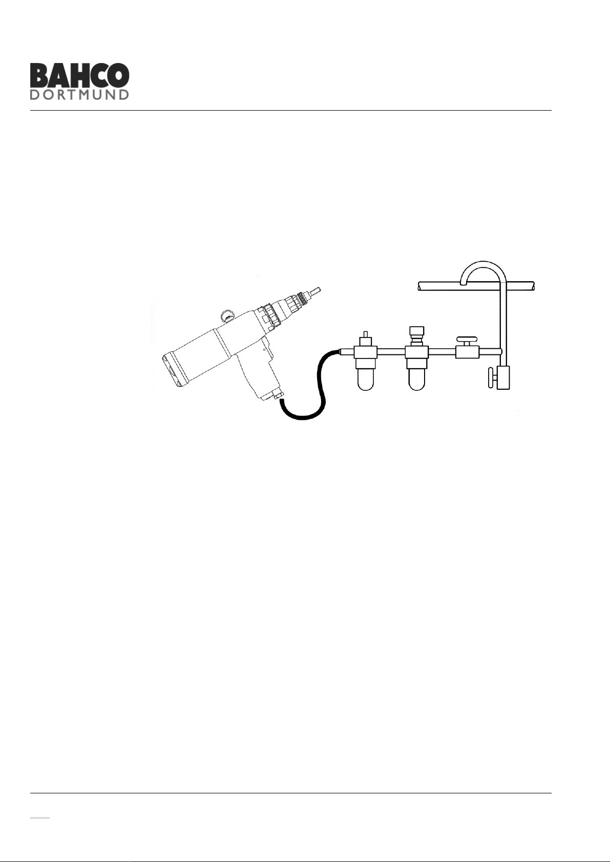
Operating Procedure
Y!Z())%5-!-8%!-((,!-(!-8%!5(2'0%&&%3!1*0!&6'',.#
Y![(&*-*()!-8%!+,*)3!0*;%-!)6-!()!-8%!\1)30%,!(1). A slight pressure on the upper half of the
Trigger (34) starts the clockwise rotation of the engine and the nut is spinded onto the
Mandrel as far as the stop on the mouthpiece.
Y!X)&%0-!+,*)3!0*;%-!)6-!CI!]!-(!-8%!',1-%!*)-(!-8%!&%--*):!8(,%#
Y