Dafra DNP3212-2 User manual

PLEASE SPEND 2 MINUTES READING
THESE INSTRUCTIONS BEFORE USING
YOUR NEW DNP3212-2 RIVNUT TOOL.
TRUST US, IT WILL SAVE YOU TIME AND
INCONVENIENCE IN THE LONG RUN.
READ THIS MANUAL CAREFULLY BEFORE USING THE TOOL!
It is IMPORTANT to follow the safety instructions for adequate protection
against injuries.
- This tool should be used ONLY to set blind rivets within the TOOL’S CAPACITY. It MUST
NOT be used for other purposes, such as hammer, etc.
- This tool should be always operated with compressed air supply within the air pressure range
0.5Mpa ~ 0.7Mpa.
- Always DISCONNECT the air supply from the tool before changing tool parts, such as
mandrel, etc.
- DO NOT use the tool in the environment described as below:
fuel and combustion air.
temperature rapidly rising.
humidity, rain, water, storm and thunder, lightning.
- When the tool is suspended by the operation hook during use, be sure the tool will not fall.
- When using the tool, always carry protective goggles, protective gloves, safety helmet, and
other necessary protections. It is highly recommended for safety reasons.
- Only use genuine spare parts for maintenance and repairs.
- All repair work must be carried out by skilled personnel, when in doubt, always return the tool
to the distributor.

DNP3212-2 RIVNUT TOOL CAPACITY
Blind rivnuts M3 – M4 – M5 – M6 – M8 – M10 – M12 in all materials and styles.
TOOL SPECIFICATIONS
Air supply pressure: 0.5Mpa ~ 0.7Mpa
Output traction power: 21,000N ~ 29,400N
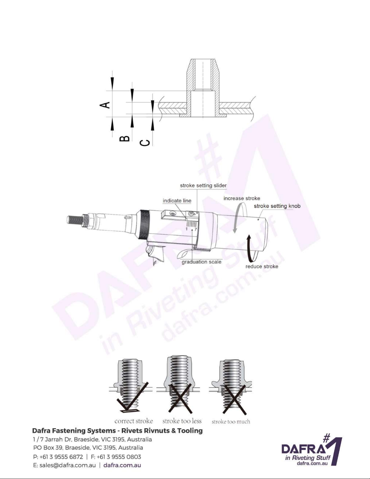
Stroke: 1mm ~ 7mm adjustable
Net weight: 1.91kgs
GETTING STARTED
Please refer to the TOOL EXPLOSIVE ILLUSTRATION and the PARTS LIST in this manual in order to
have a good understanding of the tool parts described. The descriptions of the tool parts appear in this
manual are in italics.
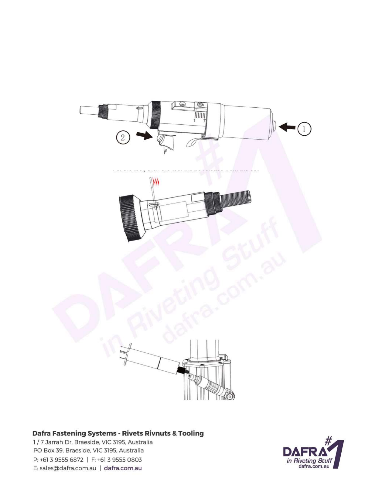
1) This pneumatic powered tool should be worked with compressed air supply. It is recommended to
use the air hose with diameter bigger than 8 mm;
2) To check the compressed air pressure within the specified range between 0,5Mpa and 0,7Mpa, and
to connect the air hose adaptor onto the tool air adaptor. The air adaptor has its different versions in
different countries and areas, normally the tools are equipped with the correct version as default, in
case the air adaptor does not apply in your air supply hose adaptor, contact the tool distributor(s);
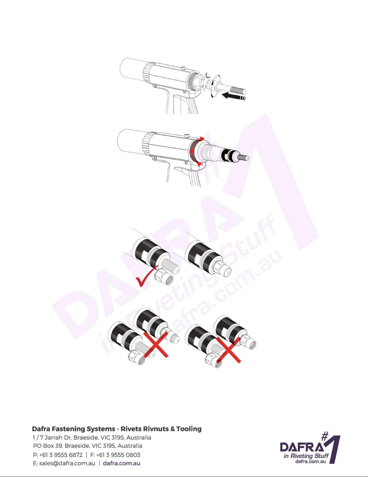
3) To change and use correct cap screw and anvil according to the size of the rivnut to be set. This tool
is equipped with cap screws and anvils from M3 up to M12 in the tool kit. For convenience, 7 identical
locknuts provided in the tool kit for each size of the cap screw and anvil in pairs;
a) To remove the anvil from the tool and the locknut:
b) To remove the retaining ring and nose sleeve:
c) To use a spanner to loosen adaptor sleeve from spring house, take out cap screw, drive bar
washer, adaptor sleeve, drive bar and spring:

d) To take the drive bar washer insert to the selected cap screw from the tool accessories pack as
per rivnut size, then mount into adaptor sleeve, drive bar together with spring and install into
spring house. To screw on adaptor sleeve tight with spring house by the spanner:
e) To screw on the retaining ring and nose sleeve back to the tool, and locknut, and anvil:
MANDREL PROTRUDING SET FOR BLIND NUT
1) To set the length of the cap screw protruding out of anvil according to blind rivnut length, by
positioning of the locknut and anvil locking each other:
2) Never to set the cap screw protruding length too long nor too short according to the rivnut to be set:

STROKE SETTING
1) It is very important step to define the stroke to be set on the tool, by measuring the rivnut and
calculating in formula: Stroke = A – ( B + C )
A = depth of the rivnut (inside of the rivnut non-threaded and no upset part of the rivnut when setting);
B = total thickness of work piece(s);
C = rivnut head thickness (if countersunk head rivnut, then C = 0);
2) To set the stroke on the tool:
a) The tool stroke can be set from 1mm up to 7mm, and it shows by the indicate line pointing on to
the graduation scale precisely;
b) To increase the stroke: slide the stroke setting slider in the direction of the tool front (cap screw),
turning the stroke setting knob anti-clock wise, release the stroke setting slider back (to be sure
the small needle tip seated back into the hole on the edge of the stroke setting knob) and checking
the indicate line pointing. Repeat the operation until the indicate line pointing at the defined stroke.
To reduce the stroke, operate in the same way but turning the stroke setting knob clock-wise.
3) Checking the set stroke by initial rivnuts setting. It is extremely important to have precise stroke
setting and trial set on work piece and refer to the illustration below to see if you got a nice set up:

TO SET RIVNUTS
1) After start-up preparations, stroke setting and initial trial setting, to put the rivnut into work piece hole
(pre-drilled), to insert the cap screw of the tool into the rivnut and press the button of the tool, the
operation of the rivnut setting will be automatically finished.
2) The tool, after the button pressed, the tool will automatically insert into the rivnut and set the rivnut
on the work piece then released automatically;
3) If users have not had the stroke setting correctly, the tool might cannot be released, then follow the
process described below to release the tool:
a) Slightly press the release button at the rear of the tool;
b) Press the button of the tool, then the tool will be release from the set rivnut.
4) If the tool operator used a bad quality rivnut or improper stroke setting, the tool might be blocked on
the set rivnut and work piece and cannot be released according to the above 3) described, then to
use the anti-block sticker in the tool kit, insert into the slot-shaped hole on the nose sleeve, then
turning the tool with force anti-lock wise to release the tool.
TOOL MAINTAINANCE
Normally after several weeks of working, for better performance of the tool, to add a few drops of
hydraulic oil on the inlet of the air adaptor of the tool in order to reduce the fictions of the tool parts since
the oil will be blown inside the tool when tool operates.

After certain period of use, the tool stroke might be reduced, it shows the hydraulic oil of the pneumatic
tool is necessary to be refilled or changed:
1) To remove the screw by hexagon wrench:
2) To connect the air supply and to cover some cloth over the hole where the screw removed, then to
press the button and the oil will be leaked out from the tool:
3) To screw the oil inject adaptor (on oil injection tube set in the accessories pack) into the hole where
screw removed:
4) To use the oil injection tube (in the accessories pack) to inject the oil slowly until not able to refill, to
remove the injection tube and its adaptor, then clean the oil on the tool and tightly screw on the screw
back to the tool:
5) To test the tool stroke. If the stroke still not enough as it should be, it means there could be some air
in the oil cylinder when you refill the oil in the tool. Then the extra air needs to be released from the
tool.
To connect the tool with air supply, to pull the tool button 6 or 7 times, then loosen the screw, let the
extra air leaking out, then screw on the screw tight again:

TOOL EXPLOSIVE ILLUSTRATION
ID in Drawing Part No. Description Qty per Tool
1 P03004-00 Cap screw M12 1
2
P00377
-
00
Anvil M12
1
3 P01090-00 Locknut 1
4
P00481
-
00
Adaptor sleeve
1
5 P00495-00 Drive bar for M12 1
6
P03003
-
00
Spring
1
7
F60074
-
00
O
-
ring 16 x 2.4
1

ID in Drawing Part No. Description Qty per Tool
8 P03962-00 Spring 1
9
F00505
-
00
Pin
1
10
P03965
-
00
Retaining ring
1
11 P03961-00 Nose sleeve 1
12
P03963
-
00
Spring seat
1
13 P03964-00 Return spring 1
14
F60038H00
O
-
ring 18 x 1.9
1
15 P03967-00 Support ring 1
16
F00031
-
00
U
-
ring 14 x 21 x 5.0
1
17
A02100
-
00
Oil cylinder
1
18 F00002-00 Washer 1
19
P00009
-
00
Screw
1
20 P03970-00 Screw 1
21
P03971
-
00
Stroke setting slider
1
22 P03969-00 Spring 1
23
P03972
-
00
Lock pin
1
24
F60200
-
00
O
-
ring 6 x 1.0
6
25 P04004-00 Hose 3
26
F00221
-
00
U
-
ring 27 x 35 x 5.0
1
27 F00222-00 O-ring 35 x 1.5 1
28
P03968
-
00
Support ring
1
29 A02097-00 Air motor 1
30
F00211
-
00
Circlip
1
31
A02255
-
00
Release button set
1
32 P03975-00 Stroke setting knob 1
33
P03986
-
00
Button
1
34 P00358-00 Pin 1
35
P03985
-
00
Switch pusher
1
36 F00115-00 O-ring 5 x 1.9 1
37
P03984
-
00
Switch sleeve
1
38
F60200
-
00
O
-
ring 6 x 1.0
1
39 F00140-00 O-ring 6 x 1.5 1
40
F00052
-
00
Steel ball
1
41 P03982-00 Hose 6.0 x 112 1
42
P03983
-
00
Hose 4.5 x 10⁹
1
43 P04001-00 Blockage end 1
44
F00174
-
00
O
-
ring
1
45
F00011
-
00
O
-
ring 12 x 1.5
1
46 P04000-00 Control rod 1
47
F00113
-
00
O
-
ring 8.4 x 2.0
1
48 A02136-00 Air cylinder lid 1
49
P03998
-
00
Rubber ball dia. 6.0
1
50
P03997
-
00
Spring
1
51 F00011-00 O-ring 12 x 1.5 1
52
P03996
-
00
Connector
1
53 F00016-00 O-ring 2
54
P04154
-
00
Air swivel joint
1
55 F00048-00 A-circlip 1
56
F00015
-
00
Air adaptor default
1
57
P04858
-
00
Screw
12
58 P03979-00 Grip 1

ID in Drawing Part No. Description Qty per Tool
59 F00315-00 Self-drilling screw 3
60
F00212
-
00
U
-
ring 10 x 16 x 4.5
1
61
P03989
-
00
Support ring
1
62 F00316-00 O-ring 24 x 1.5 1
63
P03990
-
00
Nut
1
64 F00040-00 O-ring 13 x 1.5 1
65
F00317
-
00
O
-
ring
1
66 A02096-00 Piston 1
67
F00226
-
00
Dust ring 8 x 12 x 3.5
1
68
P00051
-
00
Spring
1
69 P00052-00 Gasket 1
70
F00049
-
00
Circlip
1
71 P03994-00-96 Air cylinder black 1
72
F00227
-
00
O
-
ring
1
73 P03995-00 Air cylinder bottom 1
74
F00299
-
00
Self
-
drilling screw
1
accessory
P00378
-
00
Anvil M10
1
accessory P00306-00 Anvil M8 1
accessory
P00307
-
00
Anvil M6
1
accessory P00308-00 Anvil M5 1
accessory
P00309
-
00
Anvil M4
1
accessory P00310-00 Anvil M3 1
accessory
P01090
-
00
Locknut
6
accessory
P00488
-
00
Drive bar washer for M8
1
accessory P00487-00 Drive bar washer for M6 1
accessory
P00486
-
00
Drive bar washer for M5
1
accessory P00485-00 Drive bar washer for M4 1
accessory
P00484
-
00
Drive bar washer for M3
1
accessory P00489-00 Drive bar for M10 1
accessory
P00494
-
00
Drive bar for M8
1
accessory
P00493
-
00
Drive bar for M6
1
accessory P00491-00 Drive bar for M5 1
accessory
P00490
-
00
Drive bar for M4
1
accessory P00492-00 Drive bar for M3 1
accessory
P03005
-
00
Cap screw M10
1
accessory P03006-00 Cap screw M8 1
accessory
P03007
-
00
Cap screw M6
1
accessory
P03008
-
00
Cap screw M5
1
accessory P03009-00 Cap screw M4 1
accessory
P03010
-
00
Cap screw M3
1
accessory P04714-00 Anti-block sticker 1
accessory
A02254
-
00
Injection tube
1
accessory
P04156
-
00
Hook
1
accessory P03215-00 Wrench 1
accessory
P03200
-
00
Hook
-
shaped wrench
1
Table of contents
Other Dafra Rivet Tools manuals
Popular Rivet Tools manuals by other brands

Sioux Tools
Sioux Tools 270A Instructions-parts list

FSI
FSI PT-4000H operating instructions

RidgeGate
RidgeGate AVAK MaxDuty Swivel Series instruction manual

Gage Bilt
Gage Bilt GB752SVSRVT-5 Original instructions

Stanley
Stanley AV 20 Instruction and service manual

FAR
FAR RAC 210 TRANSLATION OF ORIGINAL INSTRUCTIONS