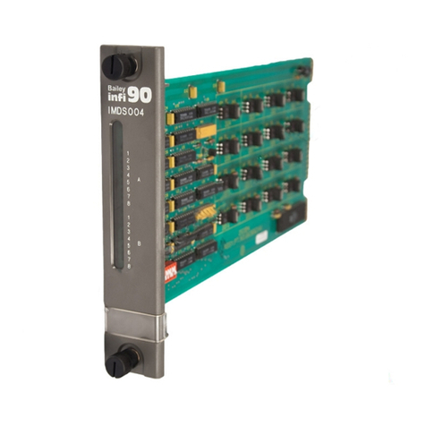
Bailey infi 90 IISAC01 User manual

®
®
Process Control and
Automation Solutions
from Elsag Bailey Group
E96-117
Analog Control Station
(IISAC01)

WARNING notices as used in this instruction apply to hazards or unsafe practices that could result in
personal injury or death.
CAUTION notices apply to hazards or unsafe practices that could result in property damage.
NOTES highlight procedures and contain information that assists the operator in understanding the
information contained in this instruction.
WARNING
INSTRUCTION MANUALS
DO NOT INSTALL, MAINTAIN, OR OPERATE THIS EQUIPMENT WITHOUT READING, UNDERSTANDING,
AND FOLLOWING THE PROPER Elsag Bailey INSTRUCTIONS AND MANUALS; OTHERWISE, INJURY OR
DAMAGE MAY RESULT.
RADIO FREQUENCY INTERFERENCE
MOST ELECTRONIC EQUIPMENT IS INFLUENCED BY RADIO FREQUENCY INTERFERENCE (RFI). CAU-
TION SHOULD BE EXERCISED WITH REGARD TO THE USE OF PORTABLE COMMUNICATIONS EQUIP-
MENT IN THE AREA AROUND SUCH EQUIPMENT. PRUDENT PRACTICE DICTATES THAT SIGNS
SHOULD BE POSTED IN THE VICINITY OF THE EQUIPMENT CAUTIONING AGAINST THE USE OF POR-
TABLE COMMUNICATIONS EQUIPMENT.
POSSIBLE PROCESS UPSETS
MAINTENANCE MUST BE PERFORMED ONLY BY QUALIFIED PERSONNEL AND ONLY AFTER SECURING
EQUIPMENT CONTROLLED BY THIS PRODUCT. ADJUSTING OR REMOVING THIS PRODUCT WHILE IT IS
IN THE SYSTEM MAY UPSET THE PROCESS BEING CONTROLLED. SOME PROCESS UPSETS MAY
CAUSE INJURY OR DAMAGE.
AVERTISSEMENT
MANUELS D’OPÉRATION
NE PAS METTRE EN PLACE, RÉPARER OU FAIRE FONCTIONNER L’ÉQUIPEMENT SANS AVOIR LU,
COMPRIS ET SUIVI LES INSTRUCTIONS RÉGLEMENTAIRES DE Elsag Bailey. TOUTE NÉGLIGENCE À
CET ÉGARD POURRAIT ÊTRE UNE CAUSE D’ACCIDENT OU DE DÉFAILLANCE DU MATÉRIEL.
PERTURBATIONS PAR FRÉQUENCE RADIO
LA PLUPART DES ÉQUIPEMENTS ÉLECTRONIQUES SONT SENSIBLES AUX PERTURBATIONS PAR
FRÉQUENCE RADIO. DES PRÉCAUTIONS DEVRONT ÊTRE PRISES LORS DE L’UTILISATION DU MATÉ-
RIEL DE COMMUNICATION PORTATIF. LA PRUDENCE EXIGE QUE LES PRÉCAUTIONS À PRENDRE
DANS CE CAS SOIENT SIGNALÉES AUX ENDROITS VOULUS DANS VOTRE USINE.
PERTURBATIONS DU PROCÉDÉ
L’ENTRETIEN DOIT ÊTRE ASSURÉ PAR UNE PERSONNE QUALIFIÉE EN CONSIDÉRANT L’ASPECT
SÉCURITAIRE DES ÉQUIPEMENTS CONTRÔLÉS PAR CE PRODUIT. L’AJUSTEMENT ET/OU L’EXTRAC-
TION DE CE PRODUIT PEUT OCCASIONNER DES À-COUPS AU PROCÉDÉ CONTRÔLE LORSQU’IL EST
INSÉRÉ DANS UNE SYSTÈME ACTIF. CES À-COUPS PEUVENT ÉGALEMENT OCCASIONNER DES
BLESSURES OU DES DOMMAGES MATÉREILS.
NOTICE
The information contained in this document is subject to change without notice.
Elsag Bailey, its affiliates, employees, and agents, and the authors and contributors to this publication specif-
ically disclaim all liabilities and warranties, express and implied (including warranties of merchantability and
fitness for a particular purpose), for the accuracy, currency, completeness, and/or reliability of the information
contained herein and/or for the fitness for any particular use and/or for the performance of any material and/
or equipment selected in whole or part with the user of/or in reliance upon information contained herein.
Selection of materials and/or equipment is at the sole risk of the user of this publication.
This document contains proprietary information of Elsag Bailey, Elsag Bailey Process Automation, and
is issued in strict confidence. Its use, or reproduction for use, for the reverse engineering, development
or manufacture of hardware or software described herein is prohibited. No part of this document may be
photocopied or reproduced without the prior written consent of Elsag Bailey.

I-E96-117B1 15 August 1994
Preface
The IISAC01 Analog Control Station provides an operator inter-
face for INFI 90® system applications. It is a panel mounted
device that interfaces directly with a manual/auto transfer sta-
tion block configured in a multi-function processor module.
The analog control station (SAC) displays process variables,
allows set point adjustment and provides analog output man-
ual control. It also provides analog output backup in the event
of other system faults.
This instruction explains the station features, specifications,
and operation. It includes installation procedures and explains
how to troubleshoot station failures.
The system engineer or technician using the SAC station
should read and understand this instruction before installing
and operating the station. In addition, a complete understand-
ing of the INFI 90 system is beneficial.
This update covers error code 16 and contains information on
hardware and software improvements.
® INFI 90 is a registered trademark of Elsag Bailey Process Automation.

15 August 1994 I-E96-117B1
®
List of Effective Pages
Total number of pages in this instruction is 94, consisting of the following:
Page No. Change Date
Preface 31 August 1994
List of Effective Pages 31 August 1994
iii through viii 31 August 1994
1-1 through 1-9 Original
2-1 through 2-19 Original
3-1 through 3-6 Original
3-7 31 August 1994
3-8 Original
3-9 through 3-10 31 August 1994
3-11 through 3-23 Original
4-1 through 4-3 31 August 1994
4-4 through 4-9 Original
5-1 through 5-2 Original
5-3 31 August 1994
5-4 through 5-13 Original
6-1 through 6-4 Original
7-1 through 7-2 Original
8-1 Original
A-1 through A-2 Original
B-1 Original
C-1 Original
Index-1 through Index-2 31 August 1994
When an update is received, insert the latest changed pages and dispose of the super-
seded pages.
NOTE: On an update page, the changed text or table is indicated by a vertical bar in the outer mar-
gin of the page adjacent to the changed area. A changed figure is indicated by a vertical bar in the
outer margin next to the figure caption. The date the update was prepared will appear beside the
page number.

I-E96-117B1 15 August 1994 vii
Safety Summary
GENERAL
WARNINGS Equipment Environment
All components, whether in transportation, operation or storage,
must be in a noncorrosive environment.
Electrical Shock Hazard During Maintenance
Disconnect power or take precautions to insure that contact with
energized parts is avoided when servicing.
Special Handling
This module uses electrostatic sensitive devices.
SPECIFIC
WARNING Wear eye protection whenever working with cleaning solvents.
When removing solvents from printed circuit boards using com-
pressed air, injury to the eyes could result from splashing solvent as
it is blown off the printed circuit board. (p. 6-1)
SPECIFIC
CAUTION Remove a station from its housing before installing or removing the
station cable to the station housing. Failure to observe these pre-
cautions could result in equipment damage. (p. 3-22)

viii 15 August 1994 I-E96-117B1
Sommaire de Sécurité
®
AVERTISSEMENTS
D’ORDRE
GÉNÉRAL
Environnement de l’équipement
Ne pas soumettre les composants à une atmosphère corrosive lors
du transport, de l’entreposage ou l’utilisation.
Possibilité de chocs électriques durant l’entretien
Débrancher l’alimentation ou prendre les précautions pour éviter
tout contact avec des composants sous tension durant l’entretien.
Precautions de Manutention
Ce module contient des composantes sensibles aux décharges
électrostatiques.
AVERTISSEMENT
D’ORDRE
SPÉCIFIQUE
Portez toujours des lunettes de protection lorsque vous utilisez des
solvants de nettoyage. L'air comprimé servant à enlever le solvant
des cartes de circuits imprimés provoque des éclaboussures qui ris-
quent d'atteindre les yeux. (p. 6-1)
ATTENTION
D’ORDRE
SPÉCIFIQUE
Retirer le poste de son boitier avant d’installer ou de retirer le câble
du poste du boitier. Un manquement à cette précaution pourrait
causer des dommages à l’équipement. (p. 3-22)

Table of Contents
Page
I-E96-117B1 15 August 1994 iii
SECTION 1 - INTRODUCTION....................................................................................................1-1
INTRODUCTION...........................................................................................................1-1
INTENDED USER.........................................................................................................1-1
HARDWARE DESCRIPTION..........................................................................................1-1
HARDWARE APPLICATION...........................................................................................1-2
FEATURES...................................................................................................................1-2
INSTRUCTION CONTENT .............................................................................................1-3
HOW TO USE THIS INSTRUCTION ...............................................................................1-4
GLOSSARY OF TERMS AND ABBREVIATIONS .............................................................1-4
REFERENCE DOCUMENTS..........................................................................................1-6
NOMENCLATURE ........................................................................................................1-7
SPECIFICATIONS.........................................................................................................1-8
SECTION 2 - DESCRIPTION AND OPERATION........................................................................2-1
INTRODUCTION...........................................................................................................2-1
SYSTEM OPERATION...................................................................................................2-1
Analog Control Station Functions...........................................................................2-4
MODES OF OPERATION ..............................................................................................2-5
Initialization...........................................................................................................2-6
Stand-Alone Operation...........................................................................................2-6
Bypass Operation ..................................................................................................2-6
Manual Override Operation ....................................................................................2-7
Normal Operation ..................................................................................................2-8
Computer and Local Mode .....................................................................................2-8
Local Level.......................................................................................................2-9
Computer Level ...............................................................................................2-9
Basic Station .........................................................................................................2-9
Cascade Station ...................................................................................................2-10
Ratio Station........................................................................................................2-12
SAC STATION I/O CIRCUITRY ...................................................................................2-13
Bypass Circuitry ..................................................................................................2-14
Electric Drive Circuitry ........................................................................................2-16
Analog Output Circuitry.......................................................................................2-18
Analog Input Circuitry .........................................................................................2-18
SECTION 3 - INSTALLATION.....................................................................................................3-1
INTRODUCTION...........................................................................................................3-1
SPECIAL HANDLING ....................................................................................................3-1
UNPACKING AND INSPECTION ....................................................................................3-2
SELECTING OPTIONS ..................................................................................................3-2
Diagnostics (SW1, Position 1) .................................................................................3-3
Communication Rate (SW1, Position 2) ..................................................................3-3
Station Address (SW1, Positions 3 through 8) .........................................................3-4
Auto Bypass (SW2, Position 1) ...............................................................................3-4
Demand Output (SW2, Position 2) ..........................................................................3-5
Electric Drive Option (SW2, Position 3 and JP2) .....................................................3-5
DISPLAY OPTIONS .......................................................................................................3-6
Stand-Alone Mode Display Options (SW3) ..............................................................3-7
Square Root Enable (SW4, Position 1) ....................................................................3-7
Normal Mode Display Options (SW4, Positions 2, 3 and 4) ......................................3-8
Bypass/Manual Override Mode Display Options (SW4, Positions 5, 6, 7 and 8) ......3-8
Manual Override (JP1) ...........................................................................................3-9

iv 15 August 1994 I-E96-117B1
Table of Contents (continued)
Page
®
SECTION 3 - INSTALLATION
(continued)
ELECTRIC DRIVE MODE DISPLAY OPTIONS (SW3 AND SW4) ................................... 3-10
MICROCOMPUTER MODE OF OPERATION (JP3) ....................................................... 3-11
MOUNTING THE STATION HOUSING......................................................................... 3-11
Cable Lengths ..................................................................................................... 3-11
Termination Unit Cable and Wiring Installation (Single or Double Station) ........... 3-15
Termination Unit Cable Installation (Interconnected Stations).............................. 3-15
Cable Connections for the NTRL03 Termination Unit ........................................... 3-16
Cable Connections for the NIRL03 Termination Module ....................................... 3-16
Termination Module Cable Installation (without Bypass) ...................................... 3-17
Termination Module Cable Installation (with Bypass) ........................................... 3-19
Connecting Termination Cables to Station Housing ............................................. 3-22
INSERTING AND REMOVING THE ANALOG CONTROL STATION ............................... 3-22
Inserting the Analog Control Station .................................................................... 3-22
Removing the Analog Control Station................................................................... 3-23
FUNCTION CODE CONFIGURATION.......................................................................... 3-23
SECTION 4 - OPERATING PROCEDURES................................................................................4-1
INTRODUCTION .......................................................................................................... 4-1
FACEPLATE OPERATION............................................................................................. 4-1
Alphanumeric Display ........................................................................................... 4-1
Annunciators ........................................................................................................ 4-4
Bar Graph Displays ............................................................................................... 4-4
Membrane Pushbuttons ........................................................................................ 4-4
Manual Override Switch ........................................................................................ 4-4
STATION START-UP AND OPERATION......................................................................... 4-6
Stand-Alone .......................................................................................................... 4-7
Normal Operation.................................................................................................. 4-8
Changing Control Strategies in Normal Operation .................................................. 4-8
Bypass/Manual Override Operation....................................................................... 4-9
Acknowledging Alarms........................................................................................... 4-9
SECTION 5 - TROUBLESHOOTING...........................................................................................5-1
INTRODUCTION .......................................................................................................... 5-1
HOW TO USE THIS SECTION ...................................................................................... 5-1
ERROR CODES ........................................................................................................... 5-1
GENERAL FAILURES................................................................................................... 5-1
SECTION 6 - MAINTENANCE.....................................................................................................6-1
INTRODUCTION .......................................................................................................... 6-1
PREVENTIVE MAINTENANCE SCHEDULE................................................................... 6-1
EQUIPMENT AND TOOLS REQUIRED ......................................................................... 6-2
PREVENTIVE MAINTENANCE PROCEDURES .............................................................. 6-2
Printed Circuit Board Cleaning .............................................................................. 6-3
General Cleaning and Washing........................................................................ 6-3
Edge Connector Cleaning ................................................................................ 6-3
Female Edge Connector Cleaning .................................................................... 6-4
Checking Connections ........................................................................................... 6-4
SECTION 7 - REPAIR/REPLACEMENT PROCEDURES...........................................................7-1
INTRODUCTION .......................................................................................................... 7-1
STATION FUSE (F1) REPLACEMENT............................................................................ 7-2

I-E96-117B1 15 August 1994 v
Table of Contents (continued)
Page
SECTION 8 - SUPPORT SERVICES...........................................................................................8-1
INTRODUCTION...........................................................................................................8-1
REPLACEMENT PARTS AND ORDERING INFORMATION ..............................................8-1
TRAINING ....................................................................................................................8-1
TECHNICAL DOCUMENTATION ...................................................................................8-1
APPENDIX A - NTCS04 CONTROLLER/STATION TERMINATION UNIT................................A-1
INTRODUCTION.......................................................................................................... A-1
APPENDIX B - NICS01 CONTROLLER/STATION TERMINATION MODULE..........................B-1
INTRODUCTION.......................................................................................................... B-1
APPENDIX C - NIDS01 STATION TERMINATION MODULE....................................................C-1
INTRODUCTION.......................................................................................................... C-1
List of Tables
No. Title Page
1-1. Glossary of Terms and Abbreviations .....................................................................1-5
1-2. Reference Documents ............................................................................................1-6
1-3. Nomenclature ........................................................................................................1-7
1-4. IISAC01 Analog Control Station Specifications .......................................................1-8
2-1. Bypass Circuit Functions and Specifications ........................................................2-15
3-1. Dipswitch SW1 Positions 1 and 2 ...........................................................................3-3
3-2. Dipswitch SW1 Address Positions 3 through 8 .......................................................3-4
3-3. Dipswitch SW2 Positions 1 through 3 ....................................................................3-5
3-4. SAC Station Jumper Settings .................................................................................3-6
3-5. Dipswitch SW3 Positions 1 through 3 ....................................................................3-7
3-6. Dipswitch SW4 Position 1 ......................................................................................3-8
3-7. Dipswitch SW4 Positions 2 through 8 ....................................................................3-9
3-8. Dipswitch SW3 Electric Drive Mode Display Options ............................................3-10
3-9. Dipswitch SW4 Electric Drive Mode Display Options ............................................3-10
3-10. Termination Device and SAC Station Designator Relationship ..............................3-12
3-11. Cable Applications, Connections and Length Requirements..................................3-13
3-12. INFI 90 Power System Maximum Cable Length .....................................................3-14
3-13. Network 90 Power System Maximum Cable Length ..............................................3-15
4-1. Special Characters on the Alphanumeric Display ...................................................4-2
4-2. Analog Control Station Error Codes and Alarms .....................................................4-2
4-3. Annunciators.........................................................................................................4-4
4-4. Membrane Pushbutton Operation ..........................................................................4-5
5-1. Corrective Action for SAC Error Codes....................................................................5-2
5-2. Troubleshooting General Failures.........................................................................5-12
6-1. Preventive Maintenance Schedule ..........................................................................6-2
7-1. Recommended Spare Parts List ..............................................................................7-1
A-1. NTCS04 Termination Unit Dipshunt Configuration ............................................... A-1

vi 15 August 1994 I-E96-117B1
No. Title Page
List of Figures
®
1-1. Example Analog Control Station within the INFI 90 Hierarchy ............................... 1-3
2-1. SAC Station Application Example .......................................................................... 2-2
2-2. Flow Diagram of SAC Station Operation from Power Up to Normal Operation ......... 2-5
2-3. SAC Station Normal Operating Modes.................................................................... 2-8
2-4. Basic Station Configuration ................................................................................. 2-10
2-5. Module Configuration with Cascade Set Point from External Source .................... 2-11
2-6. Ratio Station Configuration ................................................................................. 2-12
2-7. Block Diagram of SAC Station Circuitry ............................................................... 2-13
2-8. Station Bypass Circuitry...................................................................................... 2-15
2-9. Electric Drive Circuit ........................................................................................... 2-17
2-10. Analog Output Circuitry ...................................................................................... 2-18
3-1. Dipswitch and Jumper Locations on the SAC Station Circuit Board ....................... 3-2
3-2. Station Housing Panel Cutout and Mounting Dimensions .................................... 3-12
3-3. Cable Connections for Two Analog Control Stations on One
TCS Termination Unit.......................................................................................... 3-16
3-4. Cable Connections for TCS Termination Unit with Multiple Interconnected
SAC Stations ....................................................................................................... 3-17
3-5. Cable Connections for the NTRL03 Termination Unit ........................................... 3-18
3-6. Cable Connections for the NIRL03 Termination Module ....................................... 3-19
3-7. Cable Connections for the ICS Termination Module with One Station,
No Bypass ........................................................................................................... 3-20
3-8. Cable Connections for the ICS and IDS Modules with Interconnected Stations
and Bypass ......................................................................................................... 3-21
4-1. SAC Faceplate ....................................................................................................... 4-1
5-1. Error Code E01 Troubleshooting Flowchart ........................................................... 5-5
5-2. Error Codes E03, E04, E05 and E06 Troubleshooting Flowchart ............................ 5-6
5-3. Error Codes E07 and E08 Troubleshooting Flowchart ............................................ 5-7
5-4. Error Code E17 Troubleshooting Flowchart ........................................................... 5-8
5-5. Error Code E18 Troubleshooting Flowchart ........................................................... 5-9
5-6. Error Code E19 Troubleshooting Flowchart ......................................................... 5-10
5-7. Error Code E20 Troubleshooting Flowchart ......................................................... 5-11
5-8. Troubleshooting Flowchart for General Operational Failures ................................ 5-13
A-1. NTCS04 Terminal Assignments..............................................................................A-2
B-1. NICS01 Terminal Assignments ..............................................................................B-1
C-1. NIDS01 Terminal Assignments ..............................................................................C-1

INTRODUCTION
I-E96-117B 1 - 1
SECTION 1 - INTRODUCTION
INTRODUCTION
The IISAC01 Analog Control Station provides process loop con-
trol and monitoring capabilities for a single loop. The analog
control station (SAC), while functionally compatible with the
NDCS03 Digital Control Station, includes additional features
not found on earlier digital control stations, including:
•Additional analog input display with square root option.
•High resolution bar graph displays.
•Five or 40-kilohertz serial link.
INTENDED USER
System engineers and technicians must read this instruction
before installing and operating the SAC station. Refer to the
Table of Contents to find specific information.
HARDWARE DESCRIPTION
The SAC station is a single printed circuit board assembly. The
board assembly is housed in a panel mounted plastic case. The
faceplate indicators and membrane switches provide the oper-
ator interface.
The faceplate has three gas plasma bar graph displays. They
provide a high resolution display of:
•Set point.
•Process variable.
•Control output (demand output) data.
An eight-character alphanumeric display shows:
•Process variable value.
•Process variable alarms.
•Set point.
•Control output (demand output).
•Operational mode.
•Error codes.

INTRODUCTION
HARDWARE APPLICATION
1 - 2 I-E96-117B
®
The front panel pushbuttons:
•Select the alphanumeric display mode.
•Select the station operational mode.
•Raise/lower set point and control output (demand output).
•Select manual override.
•Acknowledge the alarms.
HARDWARE APPLICATION
The SAC station enables monitoring a process or controlling a
process manually. One NTCS04 Control I/O Termination Unit
or an NICS01 Control I/O Termination Module with an NIDS01
Station Termination Module can interconnect up to eight sta-
tions (two chains with four stations per chain). Multiple termi-
nation devices may be interconnected together in order to
interface the desired number of stations. In an interconnecting
arrangement, the first station can have bypass capability.
Bypass allows direct control of the final control element (four to
20-milliamp output or electric drive). IMMFP01 and IMMFP02
Multi-Function Processors with firmware revision level higher
than C_0, or IMMFP031Multi-Function Processors with any
revision level can interface a maximum of 64 stations. Figure
1-1 shows an example of SAC stations within the INFI 90
hierarchy.
1. . Other modules include the IMMFC03, IMMFC04 and IMMFC05 Multi-Function Controller Modules, the IMCOM03 and
IMCOM04 Controller Modules and the IMQRC01 Quick Response Controller Module. Their functionality within the control sys-
tem is similar to the MFP module except that each module varies in control capabilities (operating specifications).
FEATURES
Low cost and compact size make the analog control station a
convenient way to add stations that have operator interface
capabilities. The maximum allowable number of stations is 64
when using an IMMFP01 or IMMFP02 module (firmware revi-
sion level C or higher and operating at 40 kilobaud) unless
used in conjunction with an NDIS01 digital indicator station.
All other applications allow a maximum of eight stations.
The SAC station operates in three modes depending on module
configuration: Basic, cascade, or ratio. The control strategies
for each station type reside in the module.
Selectable station options allow a standard current output
(four to 20 milliamps) or contact relay outputs for electric
drives when the station enters bypass operation or manual
override. Additional option selections include:
•Faceplate display format for each mode of operation.

INTRODUCTION
INSTRUCTION CONTENT
I-E96-117B 1 - 3
•Reverse acting analog output.
•Square root function on the second analog input.
•Electric drive option enable/disable.
•Five or 40-kilobaud serial link station to module communi-
cation rate.
•Auto bypass enable/disable.
•Replaceable engineering unit scales for process variable
and set point.
INSTRUCTION CONTENT
This instruction provides introductory, installation, operation,
troubleshooting and maintenance information. Read and
understand this document before placing the analog control
Figure 1-1. Example Analog Control Station within the INFI 90 Hierarchy
TO OTHER STATIONS
(32 STATIONS MAX PER
COMMUNICATIONS LINK,
64 TOTAL STATIONS MAX)
4STATIONSMAX
PER CONNECTOR
T00286A
CIS
TCS
SAC
B
(SEE NOTE)
SAC
B
SAC
B
CIS
TCS
CIS
TCS
SAC
BSAC
B
SAC SAC
SAC
SAC SAC
I/O EXPANDER BUS (MMU BACKPLANE)
MFP
1
TMP
MFP
2
NOTE:B DENOTES BYPASS-
CAPABLE STATION.
LEGEND:
CIS = CONTROL I/O MODULE
MFP = MULTI-FUNCTION PROCESSOR
MMU = MODULE MOUNTING UNIT
SAC = ANALOG CONTROL STATION
TCS = CONTROLLER/STATION TERMINATION UNIT
TMP = MULTI-FUNCTION PROCESSOR TERMINATION UNIT

INTRODUCTION
HOW TO USE THIS INSTRUCTION
1 - 4 I-E96-117B
®
station into service. This instruction contains the following
sections:
Introduction Contains an overview of the system, description of hardware,
glossary of terms and abbreviations, reference documentation
and specifications.
Description and
Operation Uses block diagrams, schematics and text to explain module
operation.
Installation Covers the preliminary steps to prepare the module for opera-
tion. It covers handling, inspection, SAC station options
(dipswitch settings) and configuration.
Operating Procedures Provides information on station start-up, front panel controls
and basic operation of the SAC station.
Troubleshooting Lists station status messages, error codes and corrective
action for SAC station failures.
Maintenance Contains a table of scheduled maintenance procedures.
Repair/Replacement
Procedures Explains how to repair and replace the SAC station.
Support Services Explains the services and training that Bailey Controls Com-
pany makes available to their customers.
Appendices Supply quick reference information on the termination devices.
HOW TO USE THIS INSTRUCTION
Read this instruction in sequence. It is important to become
familiar with the entire contents of this instruction before
using the SAC station. The organization of this instruction
enables finding needed information quickly.
1. Do the steps in Section 3.
2. Read Section 4 thoroughly before powering up the station.
3. Refer to Section 5 if a problem occurs.
4. Refer to Section 6 for scheduled maintenance require-
ments.
5. Use Section 8 for a list of replacement parts information.
GLOSSARY OF TERMS AND ABBREVIATIONS
Table 1-1 lists definitions of the terms and abbreviations used
in this instruction.

INTRODUCTION
GLOSSARY OF TERMS AND ABBREVIATIONS
I-E96-117B 1 - 5
Table 1-1. Glossary of Terms and Abbreviations
Term Definition
A/D Conversion Analog-to-digital conversion. Process of generating a digital representation of the mag-
nitude of an analog signal.
Basic Station An analog control station configuration that allows the operator to adjust the set point in
the automatic mode (closed-loop control) and the control output in the manual mode
(open-loop control). One of 3 station types available in the normal operating mode.
Bypass Operation An analog control station operating mode that provides control output for a process.
Bypass operation gives the operator direct control of the output if a primary module or
control I/O slave module failure occurs.
Cascade Station An analog control station configuration that allows an externally generated signal, such
as the output of an upstream controller, to control the set point. One of 3 station types
available in the normal operating mode.
Closed-Loop
Control System A control system in which the controlled variable is measured and compared with a
standard (set point) representing the desired performance. From this comparison (feed-
back), the system compensates to eliminate any deviation between the set point and
the controlled variable.
Control Output The control system signal that influences the operation of a final control element.
D/A Conversion Digital-to-analog conversion. Process of generating an analog signal of a magnitude
that corresponds to a digital value.
Demand Output The desired control output of the analog control station when it is in bypass operation.
Manual Override An operator initiated mode which has similar functionality as bypass mode. This mode
is entered independently of the state of the primary module and CIS module. The SAC
station ignores all serial link communications with the module while in this mode. The
SAC station controls the process directly.
MFT Machine fault timer. Reset by the processor during normal operation. If not reset regu-
larly, the MFT times out and the module stops.
Open-Loop
Control System A control system where no function of the controlled variable is used for automatic con-
trol of the system. It is not a feedback control system.
PID Proportional plus integral plus derivative control action. Control action in which the out-
put is proportional to a linear combination of the input, the time integral of input and the
time rate-of-change of input.
Primary Module Active module in a redundant configuration.
Process The collective predetermined functions performed in and by the equipment in which a
variable is to be continuously controlled.
Process Variable An input that is used by the control strategy of a control device.
Ratio Station An analog control station configuration that maintains a ratio between two variables.
The ratio of an externally generated wild variable times the controlled variable becomes
the set point that provides regulation of a third variable. One of three station types avail-
able in the normal operating mode.
RS-232-C and
RS-485 Two serial communication interface standards developed by the Electronics Industry
Association (EIA) specifying what signals and voltages will be used to transmit data
from a computer (DTE) to a modem (DCE).
Set Point Target set for a process variable or standard representing desired value of the process
variable.

INTRODUCTION
REFERENCE DOCUMENTS
1 - 6 I-E96-117B
®
REFERENCE DOCUMENTS
Table 1-2 lists the documents referenced in this instruction.
Stand-Alone An analog control station operating mode that occurs when the module cannot estab-
lish communication with the station during initialization. This mode displays analog
inputs and allows the targeting (adjustment) of the demand output to match the actual
output when normal operation begins.
Termination
Module Provides input/output connection between plant equipment and the INFI 90/
Network 90®modules.
Termination Unit Provides input/output connection between plant equipment and the INFI 90/Network 90
modules.
Wild Variable A variable that is used as a reference for a control loop.
Table 1-1. Glossary of Terms and Abbreviations (continued)
Term Definition
Table 1-2. Reference Documents
Number Title
I-E92-500-3 CBC01 Batch Command Controller
I-E92-500-7 CLC03/04 Loop Command Controller
I-E96-116 NDIS01 Digital Indicator Station
I-E96-200 Function Code Application Manual
I-E96-201 IMMFP01 Multi-Function Processor
I-E96-202 IMMFP02 Multi-Function Processor
I-E96-203 IMMFP03 Multi-Function Processor
I-E96-207 IMCOM03 and IMCOM04 Controller
I-E96-211 IMMFC03 Multi-Function Controller
I-E96-212 IMMFC04 Multi-Function Controller
I-E96-213 IMMFC05 Multi-Function Controller
I-E96-215 IMQRC01 Quick Response Controller
I-E96-306 IMCIS02 Control I/O Slave Module
I-E96-317 IMRIO02 Remote I/O Slave Module
I-E96-401 NIMP01/02 Multi-Function Processor Termination Module
I-E96-409 NICS02 Control Station Termination Module
I-E96-412 NIDS01 Station Termination Module
I-E96-413 NIMF01/02 Multi-Function Controller Termination Module
I-E96-415 NIRL03 Remote Link Termination Module
I-E96-427 NTMF01 Multi-Function Controller Termination Unit
® Network 90 is a registered trademark of Elsag Bailey Process Automation.

INTRODUCTION
NOMENCLATURE
I-E96-117B 1 - 7
NOMENCLATURE
Table 1-3 is a list of related hardware.
I-E96-428 NTMP01 Multi-Function Processor Termination Unit
I-E96-429 NTRL02 and NTRL03 Fiber Optic Remote Link and
Electrical Remote Link Termination Units
I-E96-442 NTCS04 Controller Station Termination Unit
I-E96-500 Site Planning and Preparation
Table 1-2. Reference Documents (continued)
Number Title
Table 1-3. Nomenclature
Nomenclature Hardware
CKS001 CLC controller cable
CKS002 CBC controller cable
IISAC01 Analog control station
IMCIS02 Control I/O slave module
IMCOM03/04 Controller modules
IMMFC03/04/05 Multi-function controller
IMMFP01/02/03 Multi-function processor
IMQRC01 Quick response controller
NDCS03 Digital control station
NICS01 Control I/O termination module
NIDS01 Station termination module
NIMP01/02 Multi-function processor termination module
NIRL03 Remote link termination module
NKCS01/02 SAC station cable
NKCS11/12 SAC station cable non-PVC
NKDS01 DCS cable
NKDS02 DCS cable with interconnection
NKDS03 DCS cable with connector
NKDS11 DCS cable non-PVC
NKDS12 DCS cable with interconnection non-PVC

INTRODUCTION
SPECIFICATIONS
1 - 8 I-E96-117B
®
SPECIFICATIONS
Table 1-4 lists the specifications of the SAC station.
NKDS13 DCS cable with connector non-PVC
NKSE01 Station serial extension cable
NKSE02 Station serial extension cable non-PVC
NKTD01/02 Termination station cable
NKTD11 /12 Termination station cable non-PVC
NKTU01 Termination unit cable
NKTU11 Termination unit cable non-PVC
NTCS04 Control I/O termination unit
NTRL03 Remote link termination unit
Table 1-3. Nomenclature (continued)
Nomenclature Hardware
Table 1-4. IISAC01 Analog Control Station Specifications
Property Characteristic/Value
Displays 3 gas plasma bar graphs (200 segments for process variable and set
point at 0.5% resolution, 100 segments for output at 1.0% resolution)
8-character, 14-segment, alphanumeric display
Bypass Automatic entry or selected from faceplate
Communication 5 or 40 kbaud RS-485 serial link to the controlling module through the
termination unit
40 kbaud with any IMMFP03 module or IMMFP01 and IMMFP02 mod-
ule with firmware revision level C_0 or higher
All other modules are 5 kbaud
Size 72 mm x 144 mm x 381 mm (2.82 in. x 5.67 in. x 15.0 in.)
Mounting Flush panel mounting
Supply voltage
(at the termination device) 21.6 VDC minimum, 27.0 VDC maximum
Power consumption
(at the termination device) 540 mA at 24 VDC
Analog output:
Current
Maximum load (compliance)
Accuracy
D/A resolution
Maximum load inductance
3 to 21 mA
600 Ω maximum
2.0% of span at 25°C (77°F)
8 bits
600 mH

INTRODUCTION
SPECIFICATIONS
I-E96-117B 1 - 9
Analog input:
Voltage range
Impedance
Accuracy
A/D resolution
Normal mode rejection
Common mode rejection
Common mode voltage
+0.75 VDC to +5.25 VDC maximum
>10 MΩ
1.5% of span at 25°C (77°F)
8 bit
75 dB minimum at 60 Hz
90 dB minimum at 60 Hz
±5 VDC maximum
Electric drive:
R/L Contact
M/A Signal
M/A Power
100 mA maximum (sink or source)
21.6 to 27 VDC
Electromagnetic/radio
frequency interference Values are not available at this time. Do not use communication equip-
ment any closer than 2 meters from the station panel.
Ambient temperature 0° to 70°C (32° to 158°F)
Humidity 5% to 90% relative humidity up to 55°C (131°F) (noncondensing)
5% to 40% relative humidity at 70°C(158°F) (noncondensing)
Atmospheric pressure Sea level to 3 km (1.86 mi)
Air quality Noncorrosive
Certification CSA certified for use as process control equipment in an ordinary (non-
hazardous) location.
SPECIFICATIONS SUBJECT TO CHANGE WITHOUT NOTICE.
Table 1-4. IISAC01 Analog Control Station Specifications (continued)
Property Characteristic/Value

INTRODUCTION
I-E96-117B 2 - 1
SECTION 2 - DESCRIPTION AND OPERATION
INTRODUCTION
This section contains an explanation of the operation of the
IISAC01 Analog Control Station. It gives an overview of station
operation within a control system.
SYSTEM OPERATION
A control strategy using analog control stations (SAC) is
accomplished by using function blocks configured within a
module. The module could be a multi-function processor1
(MFP). The MFP module receives its inputs from a control I/O
slave (CIS) module. The CIS module drives the control output
signal under normal operating conditions as directed by the
MFP module. The SAC station can drive the output signal dur-
ing one of the following conditions:
•The MFP module directs the SAC station to enter bypass
mode.
•Communication with the MFP module is lost and the auto
bypass option is enabled (forces the station into bypass
mode).
•The operator forces the station into manual override mode
of operation.
Field interfacing is accomplished through a termination device
via a cable connection. The CIS module communicates to the
MFP module through the I/O expander bus. The SAC station
receives and sends information from and to the MFP module
through the termination devices. Figure 2-1 shows an example
application.
During normal/automatic operation, the CIS module provides
digitized analog signals representing the process variable to the
MFP module. The operator selects a set point using the set point
pushbuttons on the station faceplate. The SAC station sends the
set point value to the MFP module for algorithm processing. The
MFP module generates a control output value based on its algo-
rithm processing. The control output value is sent to the CIS
module where it becomes a control output value to a field device.
When the operator places the SAC station in manual operation,
the operator sets the control output value via raise/lower
pushbuttons, not the MFP module control algorithm. The
1. . Other modules include the IMMFC03, IMMFC04 and IMMFC05 Multi-Function Controller Modules, the IMCOM03 and IMCOM04 Controller
Modules and the IMQRC01 Quick Response Controller Module. Their functionality within the control system is similar to the MFP mo dule except
that each module varies in control capabilities (operating specifications).
Table of contents
Other Bailey Control System manuals
Popular Control System manuals by other brands

Spohn & Burkhardt
Spohn & Burkhardt SV1C Series operating instructions

Highway Care
Highway Care HighwayGuard LDS product manual

Aventura
Aventura VPO-411PC user manual

SENSTAR
SENSTAR MX-7000 Series Installation & operation manual

Grandstream Networks
Grandstream Networks GSC3570 Quick installation guide

ICON
ICON TOTALPASS quick start guide

Paradox
Paradox CR-R885-BL Installation and operating instructions

Atlas IED
Atlas IED IP100 quick start guide

High Sec Labs
High Sec Labs SC21H-3 Quick setup guide

Carbide 3D
Carbide 3D SHAPEOKO 3 Assembly guide

Fly Sky
Fly Sky HRZ00020 user manual

Astral Pool
Astral Pool RP 9 pH only Installation and operating instructions