manuals.online logo
Brands
  1. Home
  2. •
  3. Brands
  4. •
  5. elsner elektronik
  6. •
  7. Controllers
  8. •
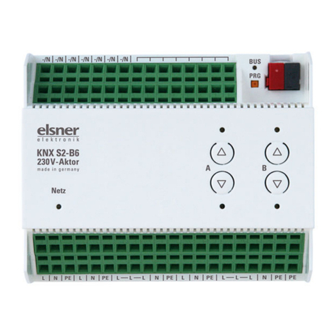
  9. elsner elektronik KNX S4-B12 DES User manual

elsner elektronik KNX S4-B12 DES User manual

KNX S4-B12 DES actuator 1
KNX S4-B12 DES actuator • Version: 28.05.2020 • Technical changes and errors excepted. • Elsner Elektronik GmbH • Sohlengrund 16 • 75395 Ostelsheim • Germany • www.elsner-elektronik.de • Technical Service: +49 (0) 7033 / 30945-250
EN
KNX S4-B12 DES
for 4 Drives with 3 Limit Switches
Technical specifications and installation instructions
1. Description
The KNX S4-B12 DES actuator is an electronic control device for controlling up
to 4 motors with 3 limit switches. A 230 V AC power supply is needed for the actua-
tor and motors.
Functions:
•4 motor outputs each for one motor with 3 limit switches (shutters with
working position)
• Switch panel with 4 switch pairs and status LEDs
•12 binary input for use as manual or bus button
•Position feedback of the movement position
•Position storage (movement position) via 1-bit object (storage and call-up,
e.g. by button)
• Controls through internal or external automatic operation
• Integrated shading control for each motor output
•Scene control for movement position with 16 scenes per motor
• Blocking objects and alarm messages have different priorities so that safety
functions always have priority (e.g. wind blocking)
•Manual or automatic control configuration per time or communication
object
Configuration is made using the KNX software ETS 5. The product file can be dow-
nloaded from the ETS online catalogue and the Elsner Elektronik website on
www.elsner-elektronik.de in the “Service” menu.
1.0.1. Scope of delivery
•Actuator
1.1. Technical data
The product is compliant with the provisions of EU Directives.
2. Installation and commissioning
2.1. Installation notes
Installation, testing, operational start-up and troubleshooting should
only be performed by an electrician.
CAUTION!
Live voltage!
There are unprotected live components inside the device.
• National legal regulations are to be followed.
• Ensure that all lines to be assembled are free of voltage and take
precautions against accidental switching on.
• Do not use the device if it is damaged.
• Take the device or system out of service and secure it against
unintentional use, if it can be assumed, that risk-free operation is
no longer guaranteed.
The device is only to be used for the intended purpose described in this manual. Any
improper modification or failure to follow the operating instructions voids any and
all warranty and guarantee claims.
After unpacking the device, check it immediately for possible mechanical damage.
If it has been damaged in transport, inform the supplier immediately.
The device may only be used as a fixed-site installation; that means only when as-
sembled and after conclusion of all installation and operational start-up tasks and
only in the surroundings designated for it.
Elsner Elektronik is not liable for any changes in norms and standards which may
occur after publication of these operating instructions.
2.2. Safety notice for automatic functions
WARNING!
Risk of injury from automatically moving components!
Parts of the system can be started by the automatic controls
and be a danger to persons.
• No persons may remain in the travelling range of parts
driven by an electric motor.
• Adhere to the relevant building regulations.
• Ensure that the return path/access to the building is not blocked
if spending time outside the building (danger of being locked out).
• Correctly decommission the system for maintenance and
cleaning work.
If there is a power outage, the system does not work. Therefore, shadings should be
moved to a save position if there are anticipated weather conditions, for example, if
this has not already been done by the automatic function (product protection).
If the power supply is removed, the connected drive switches off. When the power
is restored, the consumer remains switched off until a new movement command is
received by the actuator.
2.3. Connection
The device is suitable for operating in dry interiors. Connection according to wiring
diagram. For maintenance purposes, accessibility to the device must be guaranteed.
When installing and laying cables to the KNX connection and
the inputs for the SELV power circuits, observe the applicable
provisions and standards!
The connections for the binary inputs, including the auxiliary voltage output,
meet the requirements for SELV circuits. Mixed installation with non-SELV
circuits or mixing different auxiliary voltages is not permitted.
2.3.1. Device structure
The device is designed for series installation on mounting rails and occupies 6 mo-
dule units.
1 Output 12 V / GND
2 Internal auxiliary voltage 12 V DC, only for binary inputs
3 Binary inputs 1-12 (1 to 4: 2 connections each)
Housing Plastic
Colour White
Assembly Series installation on mounting rail
Protection category IP 20
Dimensions approx. 107 × 88 × 60 (W × H × D, mm),
6 module units
Weight approx. 340 g
Ambient temperature Operation -20…+45°C, storage -55…+90°C
Ambient humidity max. 95% RH, avoid condensation
Operating voltage 230V AC, 50 Hz
Power consumption Operation max. approx. 3.5 W
Standby max. approx. 0.6 W
Power on bus: 10 mA
Outputs 4 x motors with 2 lower end switches
(UP/DOWN1/DOWN2/N/PE).
total max. 10 A and max. 4 A per output
Maximum load Each terminal contact may be loaded with a
maximum of 10 A.
Inputs 12 × binary input, for 12 V DC
Max. cable length
Binary inputs
50 m
Data output KNX +/- bus plug terminal
BCU type Own microcontroller
PEI type 0
Group addresses max. 1024
Allocations max. 1024
Communication objects 757

Item number 70534
Fig. 1
5
6
7
910
1
4
8
2
3
11 12
KNX S4-B12 DES actuator 2
KNX S4-B12 DES actuator • Version: 28.05.2020 • Technical changes and errors excepted. • Elsner Elektronik GmbH • Sohlengrund 16 • 75395 Ostelsheim • Germany • www.elsner-elektronik.de • Technical Service: +49 (0) 7033 / 30945-250
4 Programmable LED and programmable buttons (PRG)
5 Bus terminal socket (KNX+/-)
6 Power LED (mains), shows the operation status, see chapter below
7 Key pairs Up/Down and LEDs channel A-D, for meaning of LEDs, see chapter be-
low
8 Operating voltage input 230 V AC L/N/PE
9 Output A: UP-DOWN1-DOWN2, max. 4 A
10 Output B: UP-DOWN1-DOWN2, max. 4 A
11 Output C: UP-DOWN1-DOWN2, max. 4 A
12 Output D: UP-DOWN1-DOWN2, max. 4 A
No. 9-12 in total max. 10 A!
A mix of different auxiliary voltages for the binary inputs is not permitted
2.3.2. Display of operating status by the power LED
2.3.3. Status display with the channel LEDs
2.4. Notes on mounting and commissioning
Device must not be exposed to water (rain). This could result in the electronic being
damaged. A relative air humidity of 95% must not be exceeded. Avoid bedewing.
After the operating voltage has been applied, the device will enter an initialisation
phase lasting a few seconds. During this phase no information can be received or
sent via the bus.
For KNX devices with safety functions (e.g. wind or rain block), a cyclical monitoring
of the safety objects must be established. The ideal ratio is 1:3 (example: if the we-
ather station sends a value every 5 minutes, the actuator must be configured for a
monitoring period of 15 minutes).
2.5. Operating instructions
WARNING!
Risk of injury through automatically moving components!
Parts of the system can be started by the automatic controls and
put people in danger.
• Keep movement area of the motors/hangings clear.
• Ensure that the return path/access to the building is not blocked
if spending time outside the building (danger of being locked out).
• Correctly switch off system for maintenance and cleaning
work.
If there is a power outage, the system does not work. Shades, for example, should
therefore be moved into a safe position if there are threatening weather conditions
if this has not already been down by the automatic function (Product protection).
If the 230 V AC power supply is removed, the connected drive switches off. When
the power is restored, the consumer remains switched off until a new movement
command is received by the actuator.
2.6. Connection example
Motors and mains supply cable each 5× 1.5 mm²
3. Addressing of the device at the bus
The device is supplied with the bus address 15.15.255. You can program another ad-
dress into the ETS by overwriting the 15.15.255 address or by teaching via the pro-
gramming button.
4. Disposal
After use, the device must be disposed of or recycled in accordance with the legal
regulations. Do not dispose of it with the household waste!
behaviour Colour
On Green Normal mode
Bus connection/bus voltage present.
Flashes Green Normal mode
No bus connection/bus voltage present.
On Orange Device starts or is programmed via the ETS.
No automatic functions are being performed.
Flashes Green (on),
Orange (flas-
hing)
Programming mode active.
behaviour LED
On top Motor in top position.
On bottom Motor in bottom position.
Flashes
slowly
top Motor moving up.
Flashes
slowly
bottom Motor moving down.
Flashes qui-
ckly
top Motor in top position, blocking active.
Flashes qui-
ckly
bottom Motor in bottom position (DOWN2),
block active.
Flashes qui-
ckly
both simulta-
neously
Drive in intermediate position, block
active.
Off both Drive in intermediate position.
"Running
light" across
all LEDs
all channels Wrong application version was loaded.
Use the version compatible with the
device!
Key for
Mains
230V AC
Motor A
e.g.
Central key
Up
Down
Fig. 2
Motors B, C and D correspondingly
to output B, C, D
Up
Down
Each terminal contact may be loaded with a
maximum of 10 A.

Other elsner elektronik Controllers manuals

elsner elektronik Cala Touch KNX User manual

elsner elektronik

elsner elektronik Cala Touch KNX User manual

elsner elektronik KNX S-B4T-UP 230 V Instruction manual

elsner elektronik

elsner elektronik KNX S-B4T-UP 230 V Instruction manual

elsner elektronik KNX K8 Guide

elsner elektronik

elsner elektronik KNX K8 Guide

elsner elektronik KNX RF-MSG-ST User manual

elsner elektronik

elsner elektronik KNX RF-MSG-ST User manual

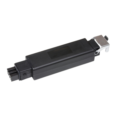
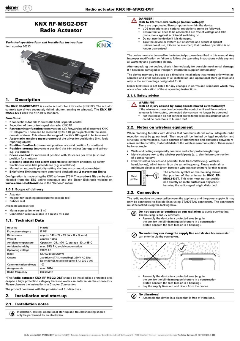
elsner elektronik RF-MSG2-DST User manual

elsner elektronik

elsner elektronik RF-MSG2-DST User manual

elsner elektronik KNX DALI L4 bc 16 A Guide

elsner elektronik

elsner elektronik KNX DALI L4 bc 16 A Guide

elsner elektronik KNX K4 User manual

elsner elektronik

elsner elektronik KNX K4 User manual

elsner elektronik KNX S-B2-UP 230 V Instruction manual

elsner elektronik

elsner elektronik KNX S-B2-UP 230 V Instruction manual

elsner elektronik KNX R1-B4 compact 16 A Guide

elsner elektronik

elsner elektronik KNX R1-B4 compact 16 A Guide

elsner elektronik 70711 User manual

elsner elektronik

elsner elektronik 70711 User manual

elsner elektronik KNX RF-MSG2-DST User manual

elsner elektronik

elsner elektronik KNX RF-MSG2-DST User manual

elsner elektronik KNX Touch One Style User manual

elsner elektronik

elsner elektronik KNX Touch One Style User manual

elsner elektronik KNX S4-B10 230 V User manual

elsner elektronik

elsner elektronik KNX S4-B10 230 V User manual

elsner elektronik KNX RF-MSG-DST Guide

elsner elektronik

elsner elektronik KNX RF-MSG-DST Guide

elsner elektronik KNX S1R-B4-UP DES Guide

elsner elektronik

elsner elektronik KNX S1R-B4-UP DES Guide

elsner elektronik KNX S1R-B4 compact Guide

elsner elektronik

elsner elektronik KNX S1R-B4 compact Guide

elsner elektronik KNX RF S1R-B2 compact Guide

elsner elektronik

elsner elektronik KNX RF S1R-B2 compact Guide

elsner elektronik Nunio KNX M-T Guide

elsner elektronik

elsner elektronik Nunio KNX M-T Guide

elsner elektronik KNX S2 User manual

elsner elektronik

elsner elektronik KNX S2 User manual

elsner elektronik KNX S1R-B4-UP DES User manual

elsner elektronik

elsner elektronik KNX S1R-B4-UP DES User manual

elsner elektronik KNX eTR 205 Light Guide

elsner elektronik

elsner elektronik KNX eTR 205 Light Guide

elsner elektronik KNX S1R-BA4-UP Guide

elsner elektronik

elsner elektronik KNX S1R-BA4-UP Guide

elsner elektronik KNX eTR MultiTouch User manual

elsner elektronik

elsner elektronik KNX eTR MultiTouch User manual

elsner elektronik KNX R4 16 A Guide

elsner elektronik

elsner elektronik KNX R4 16 A Guide

Popular Controllers manuals by other brands

RLE Technologies SeaHawk LD310 quick start guide

RLE Technologies

RLE Technologies SeaHawk LD310 quick start guide

Tunze RO Water Controller 8555 Instructions for use

Tunze

Tunze RO Water Controller 8555 Instructions for use

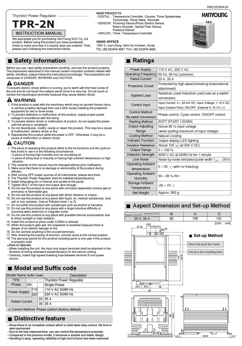
Hanyoung TPR-2N instruction manual

Hanyoung

Hanyoung TPR-2N instruction manual

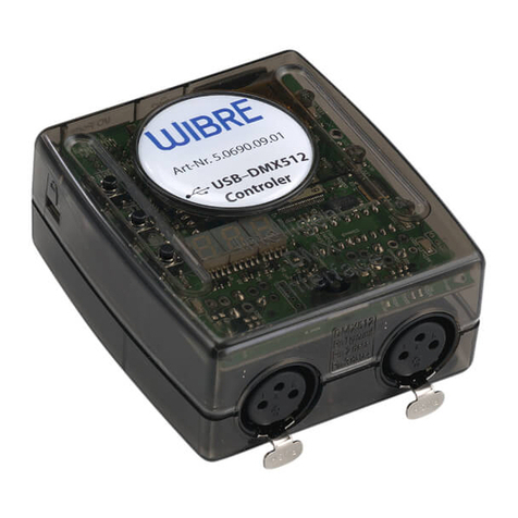
Wibre 5.0690.09.01 installation manual

Wibre

Wibre 5.0690.09.01 installation manual

Honeywell KromSchroder IC 40 technical information

Honeywell

Honeywell KromSchroder IC 40 technical information

Serato DJ INTRO NUMARK MIXTRACK PRO quick start guide

Serato

Serato DJ INTRO NUMARK MIXTRACK PRO quick start guide

Elecro Engineering Heatsmart PLUS Installation & operating manual

Elecro Engineering

Elecro Engineering Heatsmart PLUS Installation & operating manual

CRE Technology UNIGEN manual

CRE Technology

CRE Technology UNIGEN manual

Banner XS26-2 Series quick start guide

Banner

Banner XS26-2 Series quick start guide

MCS MCS-Magnum Troubleshooting

MCS

MCS MCS-Magnum Troubleshooting

Fortinet FortiADC 4000F quick start guide

Fortinet

Fortinet FortiADC 4000F quick start guide

enouvation BLE user manual

enouvation

enouvation BLE user manual

PMA KS 50 Interface description

PMA

PMA KS 50 Interface description

NI 8352 Installation Guidelines and Operating Instructions

NI

NI 8352 Installation Guidelines and Operating Instructions

WURM FRIGOLINK ANI-1F6-A manual

WURM

WURM FRIGOLINK ANI-1F6-A manual

Omron SYSMAC C series user manual

Omron

Omron SYSMAC C series user manual

Timewave PK-232SC Hardware installation manual

Timewave

Timewave PK-232SC Hardware installation manual

Cristec YPO45-12-60/MPPT user manual

Cristec

Cristec YPO45-12-60/MPPT user manual

manuals.online logo
manuals.online logoBrands
  • About & Mission
  • Contact us
  • Privacy Policy
  • Terms and Conditions

Copyright 2025 Manuals.Online. All Rights Reserved.