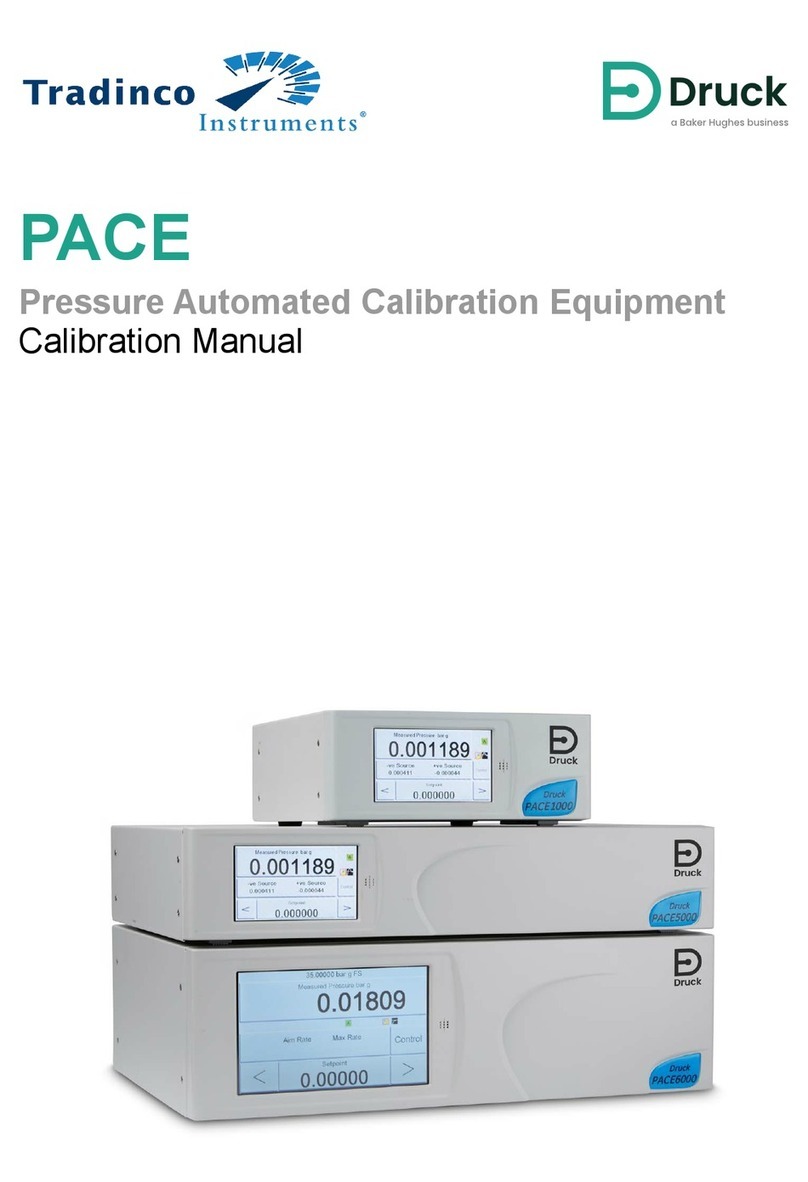
Baker Hughes Druck PACE Use and care manual


Copyright 2010 Baker Hughes Company.
English–PACE Calibration Manual | i
Contents
1. Introduction 3
2. Calibration Status 3
3. Calibration Equipment 3
4. Preliminary Operations 4
5. Notes on Calibration 4
5.1 Pressure Connection Overview 5
5.1.1 Pressure Adaptors 5
5.1.2 Pressure Connection 6
5.2 PACE Controller Connection for Output Sensor Calibration 8
5.3 PACE Controller Connection for Barometric Sensor Calibration 8
5.4 PACE Indicator Connection for Input Sensor Calibration 9
5.5 PACE Indicator Connection for Barometric Sensor Calibration 9
6. Calibration Check 9
7. Calibration Adjustment 10
8. Calibration Procedure for CM3 8 bar Absolute and Above Ranges 11
9. Recommended Calibration Check Points 11
9.1 Barometric Variant 11
9.2 2 bara / 1 barg up to 21 bara / 20 barg 12
9.3 36 bara / 35 barg and Above 12
9.4 All Other Variants (700 mbarg and Below) 13
Appendix A. PACE Menus and Screens 15
A.1 PACE Controller Menus 15
A.2 PACE Controller Screens 16
A.3 PACE Indicator Menus 17
A.4 PACE Indicator Screens 18
Appendix B. Pressure Units and Conversion Factors 19

Copyright 2010 Baker Hughes Company.
ii | PACE Calibration Manual–English

Copyright 2010 Baker Hughes Company.
English–PACE Calibration Manual | 1
Introduction
This technical manual provides calibration instructions for the PACE Pressure Controllers and
Indicators.
The features shown and described in this manual may not be available on some models.
For the full specification and user manual, refer to Druck website:
Druck.com
Safety
The manufacturer has designed this equipment to be safe when operated using the procedures
detailed in this manual. Do not use this equipment for any other purpose than that stated, the
protection provided by the equipment may be impaired.
This publication contains operating and safety instructions that must be followed to make sure of
safe operation and to maintain the equipment in a safe condition. The safety instructions are
either warnings or cautions issued to protect the user and the equipment from injury or damage.
Use qualified technicians* and good engineering practice for all procedures in this publication.
Pressure
Do not apply pressures greater than the maximum working pressure to the equipment. It is the
responsibility of the calibration technician to apply pressures within the published pressure range
and to only use external pressure equipment with correctly rated fittings and components.
Toxic Materials
There are no known toxic materials used in construction of this equipment.
Maintenance
The equipment must be maintained using the procedures in this publication. Further
manufacturer’s procedures should be done by an authorized service agents or the manufacturer’s
service departments.
Druck.com
Technical Advice
For technical advice contact the manufacturer.
WARNING Do not apply pressure greater than the maximum safe working
pressure.
* A qualified technician must have the necessary technical knowledge, documentation, special test
equipment and tools to carry out the required work on this equipment.

Copyright 2010 Baker Hughes Company.
2 | PACE Calibration Manual–English
Symbols
Abbreviations
The following abbreviations are used in this manual. Abbreviations are the same in the singular
and plural.
Symbol Description
This equipment meets the requirements of all relevant European safety directives. The
equipment carries the CE mark.
This symbol, on the equipment, indicates that the user should read the user manual.
This symbol, on the instrument, indicates that the user should refer to the user manual. This
symbol, in this manual, indicates a hazardous operation.
Ce symbole, sur l’instrument, indique que l'utilisateur doit consulter le manuel d’utilisation.
Ce symbole, dans le manuel, indique une situation dangereuse.
This symbol warns the user of the danger of electric shock.
Ce symbole alerte l’utilisateur sur le danger de choc électrique.
Do not dispose of this product as household waste. Use an approved organization that
collects and/or recycles waste electrical and electronic equipment. For more information,
contact one of these:
- Our customer service department: Druck.com
- Your local government office.
WARNING Turn off the source pressure(s) and carefully vent the pressure
lines before disconnecting or connecting the pressure lines. Proceed with care.
Only use equipment with the correct pressure rating.
Before applying pressure, examine all fittings and equipment for damage.
Replace all damaged fittings and equipment. Do not use any damaged fittings
and equipment.
Do not exceed the maximum working pressure of the instrument.
This equipment is not rated for oxygen use.
CAUTION The ground lead of the instrument must be connected to the AC
supply protective safety ground.
Isolate the power supply before making any electrical connections to the rear
panel.
Abbreviation Description
ac Alternating Current
ft Foot
H2O Water
Hg Mercury
in Inch
kg kilogram

Copyright 2010 Baker Hughes Company.
English–PACE Calibration Manual | 3
Associated Publications
The following table lists the Druck publications referenced in this manual:
1. Introduction
PACE controllers and indicators incorporate a calibration facility. For the PACE to stay within
specification, a calibration check should be carried out at chosen intervals. If the as found
calibration data of the PACE is not within the permissible deviation, carry out a calibration
adjustment.
2. Calibration Status
The Measured Pressure/Instrument Status menu displays the calibration status of the
instrument on the front panel screen. The Calibration History lists the dates of the stored
calibration corrections.
Note: The Date and Time must be set correctly in the Measured Pressure/Global Set-
up/Calibration menu.
3. Calibration Equipment
The original Druck Calibration Certificate shows the measurement uncertainty of the original
pressure calibration standard. To preserve uncertainty of the PACE calibration, checks and
adjustments must be performed using a calibrator uncertainty of less than or equal to the original
pressure calibration standard.
m Metre
mbar millibar
Pa Pascal
PACE Pressure Automated Calibration Equipment
psi Pounds per square inch
REF Reference
SCPI Standard Commands for Programmable Instruments
°C Degrees Celsius
°F Degrees Fahrenheit
+VE Pressure input
Publication Title
K0467 PACE1000 Quick Start and Safety Instructions
K0470 PACE1000 User Manual
K0447 PACE5000/6000 User Guide and Safety Instructions
K0443 PACE5000/6000 Pressure Control Module User Manual
K0476 PACE Pressure Control Module User Guide and Safety Instructions
K0469 PACE Heritage Communications Manual
K0472 PACE Series SCPI Manual
Abbreviation Description

Copyright 2010 Baker Hughes Company.
4 | PACE Calibration Manual–English
4. Preliminary Operations
Review and become familiar with the whole procedure before performing a calibration.
Before performing a calibration:
1. Turn the PACE on and allow it to thermally stabilise (for at least 2 hours) in a thermally stable
environment.
2. Carry out a leak test as detailed in PACE User Manual K0443.
5. Notes on Calibration
The pressure calibration standard output port and the PACE reference level must be at the same
level. See illustrations below for PACE reference level. If the pressure calibration standard is not
at the PACE reference level, use height-corrected applied pressure.
Figure 1: PACE1000 Reference Level
Figure 2: PACE Control Module Reference Level
Set the PACE units of pressure to one of the required units for calibration.
1 Reference Level
1 Reference Level
1
1

Copyright 2010 Baker Hughes Company.
English–PACE Calibration Manual | 5
5.1 Pressure Connection Overview
5.1.1 Pressure Adaptors
Figure 3 shows the available range of PACE pressure adaptors.
Figure 3: Pressure Adaptors
Refer to Table 1 and the Data Sheet for more information.
WARNING Turn off the source pressure(s) and carefully vent the pressure
lines before disconnecting or connecting the pressure lines. Proceed with care.
Only use equipment with the correct pressure rating.
Before applying pressure, examine all fittings and equipment for damage.
Replace all damaged fittings and equipment. Do not use any damaged fittings
and equipment.
Do not exceed the maximum working pressure of the instrument.
This equipment is not rated for oxygen use.
Table 1: Pressure Adaptor Specification
Adaptor Part Number Specification
IO-SNUBBER-1 Restrictor/Snubber
IO-DIFFUSER-1 Diffuser
IO-ADAPT-1/4NPT ISO 228 G1/8 Male to 1/4 NPT Female.
IO-SNUBBER-1 IO-DIFFUSER-1
IO-ADAPT-G1/4
IO-ADAPT-1/8NPT
IO-ADAPT-1/4NPT
IO-ADAPT-7/16UNF
IO-ADAPT-AN4
IO-ADAPT-AN6
IO-ADAPT-BARB
IO-ADAPT-G1/8

Copyright 2010 Baker Hughes Company.
6 | PACE Calibration Manual–English
5.1.2 Pressure Connection
The PACE has parallel thread pressure connectors. Use only the connector type specified in
Table 2.
IO-ADAPT-1/8NPT ISO 228 G1/8 Male to 1/8 NPT Female.
IO-ADAPT-7/16UNF ISO 228 G1/8 Male to 7/16-20 UNF Female.
IO-ADAPT-AN4 ISO 228 G1/8 Male to AN4 37° Male.
IO-ADAPT-AN6 ISO 228 G1/8 Male to AN6 37° Male.
IO-ADAPT-BARB ISO 228 G1/8 Male to 1/4 Hose.
IO-ADAPT-G1/4 ISO 228 G1/8 Male to ISO 228 G1/4 Female.
IO-ADAPT-G1/8 ISO 228 G1/8 Male to ISO 228 G1/8 Female.
WARNING Parallel threads must be used. Female thread type is parallel
thread to ISO228/1 (DIN ISO228/1, JIS B0202) G1/8.
Tapered threads not allowed.
Table 2: PACE Pressure Connector Thread Specification
PACE Connector Thread Specification
Supply +, Supply -, Output,
Vent, Reference
ISO228/1 G1/8 Parallel Threads (DIN ISO228/1, JIS B0202)
Table 1: Pressure Adaptor Specification
Adaptor Part Number Specification

Copyright 2010 Baker Hughes Company.
English–PACE Calibration Manual | 7
Refer to Figure 4 for connection to the PACE pressure connectors.
Figure 4: PACE Pressure Connection
For pressures less than 100 bar (1450 psi), see alternative sealing method in Figure 5.
Figure 5: Alternative Sealing Method for < 100 bar (1450 psi)
1 PACE pressure connector. 2 Bonded seal.
3 ISO228/1 G1/8 pressure connector. 4 NPT thread pressure connector.
5 Pressure adaptor, see Section 5.1.1.
1 PACE pressure connector.
2 Bonded seal.
3 ISO228/1 G1/8 pressure connector or adaptor. For
adaptors, see Section 5.1.1.
1
1
3
4
45
1
2
2
1
3
2

Copyright 2010 Baker Hughes Company.
8 | PACE Calibration Manual–English
5.2 PACE Controller Connection for Output Sensor Calibration
1. Fit a blanking plug to the SUPPLY – input of the PACE controller.
2. Fit an on/off valve to the SUPPLY + input of the PACE controller. Leave the other side of the
valve open to atmosphere.
3. Turn the on/off valve to the closed position.
4. Connect the output of the pressure calibration standard to the PACE module output port.
Note: For gauge sensor calibration, apply positive and negative gauge pressures to the
PACE output port.
5. To attenuate changes in atmospheric pressure, or changes due to drafts, connect the PACE
reference port to the pressure calibration standard reference port. If a reference connection
is unavailable, fit snubber IO-SNUBBER-1 to the PACE reference port.
5.3 PACE Controller Connection for Barometric Sensor Calibration
1. Connect the output of the pressure calibration standard to the PACE module reference port.
WARNING On completion of calibration, open the on/off valve (5) to vent
trapped pressure from the SUPPLY + port to atmosphere.
INFORMATION For optimum performance, connect the PACE reference port
to the pressure calibration standard. If unavailable, fit snubber IO-SNUBBER-1 to
the PACE reference port.
1 PACE Pressure Controller (viewed from rear). 2 Control Module 2.
3 Control Module 1. 4 Pressure calibration standard.
5 On/Off valve.
1 PACE Pressure Controller (viewed from rear). 2 Control Module 2.
3 Control Module 1. 4 Pressure calibration standard.
SUPPLY OUTLET VENT REF SUPPLY OUTLET VENT REF
1 4
2 3
5
SUPPLY OUTLET VENT REF SUPPLY OUTLET VENT REF
1 4
2 3

Copyright 2010 Baker Hughes Company.
English–PACE Calibration Manual | 9
5.4 PACE Indicator Connection for Input Sensor Calibration
1. Connect the output of the pressure calibration standard to the PACE input port.
Note: For gauge sensor calibration, apply positive and negative gauge pressures to the
PACE input port.
2. To attenuate changes in atmospheric pressure, or changes due to drafts, connect the PACE
reference port to the pressure calibration standard reference port. If a reference connection
is unavailable, fit snubber IO-SNUBBER-1 to the PACE reference port.
5.5 PACE Indicator Connection for Barometric Sensor Calibration
1. Connect the output of the pressure calibration standard to the PACE reference port.
6. Calibration Check
Note: The PACE adds the barometric reading to a gauge range to produce a pseudo-absolute
range (for CM2 and below). For CM3 the PACE adds the barometric reading to an absolute range
to produce a pseudo-gauge range.
For PACE calibration menus, refer to Appendix A
To check the calibration of PACE, proceed as follows:
1. Connect the PACE to the pressure calibration standard. Refer to Section 5.
2. Press Task and select Basic.
INFORMATION For optimum performance, connect the PACE reference port
to the pressure calibration standard. If unavailable, fit PACE snubber
IO-SNUBBER-1 to the PACE reference port.
1 PACE Pressure Indicator (viewed from rear). 2 Pressure calibration standard.
INFORMATION Gauge ranges (for CM3 8 bar absolute ranges and above see
Section 8) should be zeroed immediately prior to a calibration check. Zeroing is
not required for CM3 2 bar / 3.5 bar.
+VE REF
21
+VE+VE
+VE REF
21
+VE+VE

Copyright 2010 Baker Hughes Company.
10 | PACE Calibration Manual–English
3. With the pressure calibration standard connected to the correct pressure port, select
Measured Pressure and press Range to select the pressure range to be checked.
4. Barometric pressure can be displayed in the status area for -B variants.
5. Set maximum displayed resolution.
6. Press Measured Pressure/Zero to zero the selected gauge range.
7. On completion of the zero operation, the display shows Zero completed successfully.
8. Adjust calibration pressure to the first pressure value and wait until this pressure, as
displayed on PACE, is stable to less than 5 ppm (0.0005%) for CM2 and below (aim for
1ppm (0.0001%) on CM3). Display filtering may be required.
9. Compare the pressure value on the pressure calibration standard to the value displayed on
the PACE and record the difference.
10. Repeat (8) and (9) for each pressure, as prompted by the PACE.
11. If the recorded difference exceeds the permissible deviation (accuracy) for the selected
range, the calibrator requires a calibration adjustment for that range. Refer to PACE Data
Sheet for permissible precision deviation and accuracy.
Note: If it has been less than 24 hours since calibration, the PACE specification equals the
Data Sheet precision specification with respect to the original pressure calibration standard.
If it has been greater than 24 hours since calibration, the PACE specification is the sum of
the Data Sheet precision and the long term stability specification with respect to the original
pressure calibration standard. It is recommended that an adjustment is performed on a new
instrument and/or if the deviation measured is greater than 70% of the 1-Year uncertainty
specification.
12. Select the next pressure range for a calibration check.
13. After completing all calibration checks, adjust the pressure calibration standard to
atmospheric pressure.
14. Disconnect pressure calibration standard from the output.
15. If no further calibration is required, switch off the PACE.
7. Calibration Adjustment
For PACE calibration menus, refer to Appendix A
To adjust the calibration of PACE, proceed as follows:
1. Connect the PACE to the pressure calibration standard. Refer to Section 5.
Note: Calibration adjustments may be carried out in any order. Three calibration points are
required for gauge sensors. Two calibration points are required for absolute sensors.
2. Select Measured Pressure/Global Set-up/Calibration and enter the Calibration
PIN (4321).
3. Select Sensor Correction.
4. Select the pressure range to be corrected.
5. Select the pressure sensor to be corrected.
6. Select Calibration Adjustment.
7. The display shows the first value to be set on the pressure calibration standard and to press
OK when the applied pressure is stable to less than 5 ppm (0.0005%) for CM2 and below
(aim for 1 ppm (0.0001%) on CM3). Use the numeric keys to enter the precise applied
pressure.
Note: The display also shows throughout this procedure the message Calibrating and the
selected pressure range.

Copyright 2010 Baker Hughes Company.
English–PACE Calibration Manual | 11
8. Select Accept to store the first value and the display goes to the next pressure value to be
set.
9. Select Repeat to re-apply the same pressure and Quit Calibration to exit the calibration of
this pressure range.
10. Repeat steps (6) to (8) for the next value.
11. Carry out a calibration check to verify this procedure. Refer to Section 6.
12. After completing the calibration procedures, adjust the pressure calibration standard to
atmospheric pressure. Disconnect the pressure calibration standard from the PACE.
13. If no further calibration is required, switch off the PACE.
8. Calibration Procedure for CM3 8 bar Absolute and
Above Ranges
1. Carry out a calibration check (Section 6 steps (1) to (5) and (8) to (14)) on the Barometer
first. If the recorded difference exceeds the permissible deviation then the Barometer must
be adjusted (see Section 7).
Note: If stability is difficult to maintain then the home screen (showing pressure readings)
can be used with 7 digits. If the number of digits is reduced, then the error due to reduced
resolution must be considered with respect to the error budget.
2. Carry out an atmospheric zero on the CM3 reference sensor as per Section 6 of the user
manual K0443 prior to the calibration check. This will zero the reference sensor against the
barometer to remove any drift.
3. Carry out steps (1) to (5) and (8) to (15) of Section 6 for the reference sensor. Note that the
gauge control sensor does not require calibration on CM3 units.
Note: To enable the barometric reading, select the Status Area > Global Setup > Display > Status
Area > Barometric. It is important to consider that this step is not possible with the barometer
unless the CM3-B option is enabled in the module identity window within the engineering menu
(only accessible by Druck service centers). If this option is not available then skip step (2).
9. Recommended Calibration Check Points
9.1 Barometric Variant
750 mbar
900 mbar
950 mbar
1050 mbar
1150 mbar
1050 mbar
1000 mbar
950 mbar
900 mbar
750 mbar

Copyright 2010 Baker Hughes Company.
12 | PACE Calibration Manual–English
9.2 2 bara / 1 barg up to 21 bara / 20 barg
9.3 36 bara / 35 barg and Above
35 mbara / -965 mbarg
20% of full-scale pressure
40% of full-scale pressure
60% of full-scale pressure
80% of full-scale pressure
100% of full-scale pressure
80% of full-scale pressure
60% of full-scale pressure
40% of full-scale pressure
20% of full-scale pressure
35 mbara / -965 mbarg
Atmospheric / 0 mbarg
20% of full-scale pressure
40% of full-scale pressure
60% of full-scale pressure
80% of full-scale pressure
100% of full-scale pressure
80% of full-scale pressure
60% of full-scale pressure
40% of full-scale pressure
20% of full-scale pressure
Atmospheric / 0 mbarg

Copyright 2010 Baker Hughes Company.
English–PACE Calibration Manual | 13
9.4 All Other Variants (700 mbarg and Below)
0mbarg
-100% of full-scale pressure
-80% of full-scale pressure
-60% of full-scale pressure
-40% of full-scale pressure
-20% of full-scale pressure
0mbarg
20% of full-scale pressure
40% of full-scale pressure
60% of full-scale pressure
80% of full-scale pressure
100% of full-scale pressure
0mbarg

Copyright 2010 Baker Hughes Company.
14 | PACE Calibration Manual–English

Copyright 2010 Baker Hughes Company.
English–PACE Calibration Manual | 15
PACE Controller Menus
Appendix A. PACE Menus and Screens
A.1 PACE Controller Menus
Calibration procedure next page

Copyright 2010 Baker Hughes Company.
16 | PACE Calibration Manual–English
Appendix A. PACE Menus and Screens
A.2 PACE Controller Screens
Table of contents
Other Baker Hughes Test Equipment manuals
Baker Hughes
Baker Hughes Druck DPI 880 User manual

Baker Hughes
Baker Hughes Druck DPI 620 Genii User manual

Baker Hughes
Baker Hughes Druck PACE Series Use and care manual

Baker Hughes
Baker Hughes Druck DPI 620 Genii Instruction Manual

Baker Hughes
Baker Hughes Druck DPI 610A User manual

Baker Hughes
Baker Hughes Druck DPI 610E-PC User manual

Baker Hughes
Baker Hughes Druck DPI 610 IS User manual

Baker Hughes
Baker Hughes Druck Dry PTC 200 User manual

Baker Hughes
Baker Hughes Druck DPI 612 User manual

Baker Hughes
Baker Hughes Druck DPI 880 User manual