Baker Hughes Druck DPI 880 User manual


Copyright 2005 Baker Hughes Company.
English–DPI880 Instruction Manual | i
A1
A2
A3
MENU
OK
HOLD
ESC
1
10
9
TC
mA +
3W
MAX30V
COM
V
Hz
mA -
4W
RTD
8
7
6
5
4
3
2
A2
A3
11
12
3xLR6(AA)
B1
30V MA
X
Vin
24Vo
mA
-mA (24Vo)+
13
14
15
1
2
Sk2Sk1
553.2
K
1372°C
CJ=0.0
13.400
55mA
1
2
MENU
OK
18 17 16
19
20
21
22
23
24
25

Copyright 2005 Baker Hughes Company.
ii | DPI880 Instruction Manual–English
B1

Copyright 2005 Baker Hughes Company.
English–DPI880 Instruction Manual | 1
Contents
1. To Start 2
1.1 Location of Items 2
1.2 Items on the Display 2
1.3 Prepare the Instrument 3
1.4 Power On or Off 3
1.5 Set up the Basic Operation 3
1.6 Select a Task (Measure and/or Supply) 3
1.7 Set Up the Settings 4
2. Operation 5
2.1 Electrical Connections 6
2.2 Communications Port Connections 6
2.3 Change the Output Values 6
2.4 Measure/Supply mA 6
2.5 Measure/Supply Volts or mV 7
2.6 Measure/Supply Hz or Pulses 7
2.7 RTD/Ohms Connections 8
2.8 Thermocouple (TC) Connections 8
2.9 Transmitter Calibration 9
2.10 Switch Test 9
2.11 UPM Pressure Measurements 10
2.12 Error Indications 10
3. Maintenance 10
3.1 Return Goods/Material Procedure 10
3.2 Clean the Unit 11
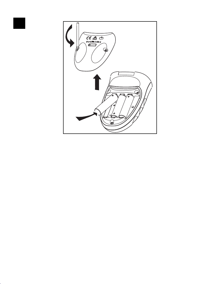
3.3 Replace the Batteries 11
4. Calibration 11
4.1 Before You Start 11
4.2 Procedures: mA Input 11
4.3 Procedures: mA Output 12
4.4 Procedures: mV/Volts Input 12
4.5 Procedures: mV/Volts Output 12
4.6 Procedures: Hz Input/Output 12
4.7 Procedures: CJ Input 13
4.8 Procedures: RTD (Ohms) Input 13
4.9 Procedures: RTD (Ohms) Output 13
4.10 Procedures: TC (mV) Input/Output 14
4.11 Procedures: IDOS UMM 14
5. Specification 14
5.1 General 14
5.2 Electrical (Figure A1 - Item 10) 14
5.3 Electrical Connectors (Figure A2) 15
5.4 Temperature Ranges (RTD) 15
5.5 Resistance Ranges (Ohms/RTD) 15
5.6 Frequency 15
5.7 Temperature Ranges (TC) 16
5.8 mV (TC) Range 16
Introduction
The DPI880 Multi-function Calibrator is part of the Druck
DPI8XX series of hand held instruments.
This series of instruments uses Intelligent Digital Output
Sensor (IDOS) technology to give instant plug and play
functionality with a range of Universal Measurement
Modules (UMM). Example: the Universal Pressure Module
(UPM).
The DPI880 includes these functions:
• Measure mA, Volts/mV, Hz/pulse count
• Supply mA, Volts/mV, Hz/pulse count
• Measure/simulate:
i. Resistance Temperature Detector (RTD): Ω or
°C/°F
ii. thermocouple (TC): mV or °C/°F
iii. a resistor (Ω)
• Cold Junction (CJ) compensation: Automatic/Manual
• Step/Ramp functions: Automatic/Manual
• Communications port: IDOS or RS 232
• Language selection (Refer to Table 1)
•1Measure pressure/Leak test: External IDOS UPM
•1Snapshot: Up to 1000 displays with a date/time stamp
• 250Ω series resistor. Use this instrument together with
a HART® communicator to set up and calibrate
HART® devices.
• Switch test
• Other functions: Hold, Backlight
Safety
Before you use the instrument, make sure that you read
and understand all the related data. This includes: all local
safety procedures, the instructions for the UMM (if
applicable), and this publication.
Before you start an operation or procedure in this
publication, make sure that you have the necessary skills (if
necessary, with qualifications from an approved training
establishment). Follow good engineering practice at all
times.
1. Optional item.
WARNING Do not use with media that has
an oxygen concentration > 21 % or other
strong oxidizing agents.
This product contains materials or fluids that
may degrade or combust in the presence of
strong oxidizing agents.
It is dangerous to ignore the specified limits
for the instrument or to use the instrument
when it is not in its normal condition. Use the
applicable protection and obey all safety
precautions.
Do not use the instrument in locations with
explosive gas, vapor or dust. There is a risk of
an explosion.
To prevent electrical shocks or damage to the
instrument, do not connect more than 30 V
between the terminals, or between the
terminals and the ground (earth).
UPM only. To prevent a dangerous release of
pressure, isolate and bleed the system before
you disconnect a pressure connection.

Copyright 2005 Baker Hughes Company.
2 | DPI880 Instruction Manual–English
Marks and Symbols on the Instrument
1. To Start
1.1 Location of Items
Refer to Figure A1 and Figure A2.
1.2 Items on the Display
Refer to Figure A3.
Symbol Description
This equipment meets the requirements of all
relevant European safety directives. The equipment
carries the CE mark.
This equipment meets the requirements of all
relevant UK Statutory Instruments. The equipment
carries the UKCA mark.
This symbol, on the equipment, indicates that the
user should read the user manual.
This symbol, on the equipment, indicates a warning
and that the user should refer to the user manual.
Ground (Earth)
On/Off
Battery
Druck is an active participant in the UK and EU
Waste Electrical and Electronic Equipment (WEEE)
take-back initiative (UK SI 2013/3113, EU directive
2012/19/EU).
The equipment that you bought has required the
extraction and use of natural resources for its
production. It may contain hazardous substances
that could impact health and the environment.
In order to avoid the dissemination of those
substances in our environment and to diminish the
pressure on the natural resources, we encourage
you to use the appropriate take-back systems.
Those systems will reuse or recycle most of the
materials of your end life equipment in a sound way.
The crossed-out wheeled bin symbol invites you to
use those systems.
If you need more information on the collection,
reuse, and recycling systems, please contact your
local or regional waste administration.
Please visit the link below for take-back instructions
and more information about this initiative.
https://druck.com/weee
Item Description
1. On or off button.
2. Left-hand soft-key. Selects the function above
it on the display (Item 24). Example: Edit
3. Moves back one menu level.
Leaves a menu option.
Cancels the changes to a value.
ESC
4.
Increases or decreases a value.
Highlights a different item.
5. Holds the data on the display. To continue,
press the HOLD button again.
6. Shows the Select Task menu (Item 25).
Selects or accepts an item or value.
Selects [] or cancels [ ] a selection.
7.
Right-hand soft-key. Selects the function
above it on the display (Item 24). Example:
Settings
8. Display. Refer to Figure A3.
9. SENSOR/
PC
Communications port. Use to connect a
Universal Measurement Module (UMM) or a
RS 232 cable.
10. Connectors to measure or supply the specified
values. Refer to “Operation”.
COM Common connector
3W, 4W 3-wire, 4-wire RTD input
11. Connection point for some of the optional
accessories. Refer to the datasheet.
12. Battery compartment. Refer to Figure B1.
13., 14., 15. (Dual Function) Connectors to measure or
supply the specified values. Refer to
“Operation”.
Vin, Volts input or switch
24Vo 24V loop power supply
Item Description
16. Task indication for the switch test.
= switch closed.
= switch open.
UPM only. Task indication for the leak test.
There is a 250Ω series resistor in the mA
circuit.
Refer to: Table 2 & Table 3.
17. The loop power supply is on.
Refer to: Table 2 & Table 3.
18. The data on the display is on hold. To
continue, press the HOLD button again.
19. Shows the battery level: 0 … 100%.
20. Identifies the type of data.
= Input
= Output
= IDOS input
Refer to: Table 2 & Table 3.
21. … 22. The settings applied to the input or output:
21. K The thermocouple type (K, J, T …) - (Table 4
& Table 5).
CJ=… The cold junction temperature (Table 1).
Pt… The RTD type (Pt50, …) - (Table 4 & Table 5).
RTD input connections: 2, 3, or 4 (Figure 7).
Item Description
HOLD
MENU
OK

Copyright 2005 Baker Hughes Company.
English–DPI880 Instruction Manual | 3
1.3 Prepare the Instrument
Before you use the instrument for the first time:
• Make sure that there is no damage to the instrument,
and that there are no missing items.
• Remove the plastic film that protects the display. Use
the tag () in the top right-hand corner.
• Install the batteries (refer to Figure B1). Then re-attach
the cover.
1.4 Power On or Off
To set the power on or off, press (Figure A1 - Item 1).
The instrument does a self test and then shows the
applicable data.
When the power is off, the last set of configuration options
stays in memory. Refer to “Maintenance”.
1.5 Set up the Basic Operation
Use the Set Up menu to set up the basic operation of the
instrument.
If there is additional data for a menu option, select Settings
() to see the values that are set up. If necessary, adjust
the values.
1.6 Select a Task (Measure and/or Supply)
When the instrument is set up (Table 1), use the task
selection menu to select the applicable task.
5.0V …V = The input trigger level (Table 4) or the
output amplitude (Table 5).
22. , …, = Output operation (Table 5).
23. 13.400
55mA
The measured values applicable to the task
selections in Item 25, area and + the
measurement range and units.
24.
Sk1/2
A soft-key function. To select an available
function, press the soft-key below it. Example:
= Move left
= Move right
25. The task selection menu. One task selection is
permitted in each area ( and ).
= cursor position (flashes on/off)
= a button or task selection is set in area or
.
Sets the Dual Function, area selections to
off. This saves the battery power.
Refer to: Table 2 & Table 3.
Help: Shows a connection diagram for the task
selections you have set.
Set Up: Shows the Set Up menu to set up the
basic operation. Refer to Table 1.
OK: Accepts the selections on the menu.
Note: MENU/OK also does this.
Utilities: Leak Test. Use this function with a
UPM. Refer to Figure 13.
Snapshot: Optional item - To use this facility,
install the data logging upgrade kit. Refer to
the user manual - K0397: DPI800 series data
logging upgrade kit.
Item Description
1 2 Task selection
menu: 3 Menu:
Set Up 4 5
+
(Table 2) (Table 1) []/[ ]
Table 1: Menu Options - Set Up
Options Description
… Scale To select the applicable international
temperature scale: IPTS 68 or ITS 90.
To add a 250Ω series resistor into the mA circuit.
You can then use this instrument together with a
HART® communicator to set up and calibrate
HART® devices.
To select and set up the backlight facility + timer.
Additional data: Select Settings ()
To select and set up the power off facility + timer.
Additional data: Select Settings ()
To show the battery level (%).
To set the display contrast (%).
Increases %, decreases %
To set the time + date. The calibration facility
uses the date to give service and calibration
messages.
To set the language option.
To calibrate the instrument.
Additional data: Refer to “Calibration”.
To select and show the applicable status data.
(Software Build, Calibration Due date, Serial
Number, IDOS Information).
1 Task selection menu: 2 3 4 5
+
+
(Table 2 & Table 3) Task = mA output
MENU
OK
MENU
OK
9
MENU
OK
MENU
OK
1
2
MENU
OK
MENU
OK

Copyright 2005 Baker Hughes Company.
4 | DPI880 Instruction Manual–English
If you attach a Universal Measurement Module (UMM) to
the communications port (Figure A1 - Item 9), the task
selection menu shows the applicable IDOS options.
Make the necessary selections from each area ( and ).
One task is permitted in each area.
Note: Use the Dual Function area () to do two operations
at the same time. If the area selection is not necessary,
set this area to off (). This saves the battery power.
1.7 Set Up the Settings
When the task is set up (Table 2 & Table 3), use the
Settings menu to adjust the input and/or output operation.
If there is additional data for a menu option, select Settings
() to see the values that are set up. If necessary, adjust
the values.
Task selection menu: 6 Display:
mA output
(Table 2 & Table 3) Sk1 = Edit
Sk2 = Settings
Table 2: Menu Options - Task Selections (Dual
Function, Area )
Options
(If applicable) Description
Input measurement tasks:
mA Measure ±55 mA
V Measure ±30 V
mV Measure ±120 mV
Hz Measure the frequency (Units: Table 4)
RTD Measure RTD temperature
Ω Measure RTD resistance or Ω
TC Measure thermocouple temperature OR mV
Only when an IDOS UMM is attached. An IDOS
measurement task.
Output tasks:
mA Supply 0 to 24 mA
V Supply 0 to 12 V
mV Supply 0 to 120 mV
Hz Supply an output frequency (Units: Table 4)
RTD Simulate RTD temperature
Ω Simulate RTD resistance or Ω
TC Simulate thermocouple temperature OR mV
Table 3: Menu Options - Task Selections (Area )
Options
(If applicable) Description
White button = A Dual Function is set.
Black button = Dual Function, area is set to off.
Input measurement tasks:
mA Measure ±55 mA
V Measure ±30 V
mA/24V Measure ±55 mA (24V loop power is on)
A switch test.
Only when an IDOS UMM is attached. An IDOS
measurement task.
1
2
MENU
OK
0.000
Sk2Sk1
24mA
1
2
TC
mA +
3W
MAX30V
COM
V
Hz
mA -
4W
RTD
30V MA
X
Vin
24Vo
mA
-mA (24Vo)+
Display: Task
mA + IDOS 1 Settings selection
(If applicable) 2 3
Sk1 = Start/Stop
Sk2 = Settings
Menu:
Settings 4A 5A Display:
… units 6A 7A
(Table 4) (Table 4) []
Menu:
Settings 4B 5B
(Table 5) []
Table 4: Menu Options - Settings (Input)
Options
(If applicable) Description
… Units
Pressure Units (UPM only). If you select an
IDOS task (Table 2 & Table 3). Select one of the
fixed units of measurement (psi, mbar …).
Temperature Units (RTD or TC only). To select
the temperature units (°C or °F).
Frequency Units (Hz only). To select one of
these units:
Hz: Range < 1000 Hz
kHz: Range 0 to 50 kHz
counts/minute (cpm)
counts/hour (cph)
…
(TC only). Change the measurement operation:
Temperature to mV OR
mV to Temperature
CJ …
(TC only). To select the type of cold junction (CJ)
compensation.
Automatic: The instrument monitors the CJ
temperature and applies the necessary CJ
compensation.
Manual: Measure the CJ temperature and set
the applicable value. The instrument uses this
value to apply the necessary CJ compensation.
0.000
Sk2Sk1
24mA
0.0
10bar g
IDOS
mA
MENU
OK
… Units
MENU
OK
bar
Pa
MENU
OK
Sk2
MENU
OK

Copyright 2005 Baker Hughes Company.
English–DPI880 Instruction Manual | 5
2. Operation
This section gives examples of how to connect and use the
instrument. Before you start:
• Read and understand the “Safety” section.
• Do not use a damaged instrument.
… type Select RTD Type (RTD only). To select an
applicable RTD type (Pt50, Pt100 …)
Select TC Type (TC only). To select an
applicable thermocouple type (K, J, T …)
Trigger level
(Hz only). To set the amplitude at which the
instrument senses a frequency signal. Default =
5V.
Auto Detect []/[ ]: Set this option to make the
instrument calculate the value from the available
signal.
(UPM only). Gage sensors or sensors with
differential operation. A zero correction that
makes the instrument read zero at local
pressure.
(Leak Test only). To set an applicable period for
the leak test (Hours:Minutes:Seconds).
Table 5: Menu Options - Settings (Output)
Options
(If applicable) Description
… Units Pressure/Temperature: Refer to Table 4.
Frequency Units (Hz only). To select one of
these units:
Hz: Range < 1000 Hz
kHz: Range 0 to 50 kHz
pulses/minute (ppm)
pulses/hour (pph)
…
(TC only). Change the output operation:
Temperature to mV OR
mV to Temperature
CJ … (TC only). Refer to Table 4.
… type Refer to Table 4.
Amplitude (Hz only). To set the amplitude of the output
signal. Amplitude = 5V (Default).
To select and set up a value for the “Nudge”
output. Example: 1.000 mA increments.
Additional data: Select Settings ()
To select and set up values for the “Span Check”
output. Example output cycle:
This cycle repeats automatically.
Additional data (Table 6): Select Settings ()
Table 4: Menu Options - Settings (Input)
Options
(If applicable) Description
100%
0%
d
d
% Step
To select and set up values for the “% Step”
output. Example output cycle:
Auto Repeat - Optional
Additional data (Table 6): Select Settings ()
… Step
To select and set up values for the “Defined
Step” output. Example output cycle:
Auto Repeat - Optional
Additional data (Table 6): Select Settings ()
To select and set up values for the “Ramp”
output. Example output cycle:
Auto Repeat - Optional
Additional data (Table 6): Select Settings ()
Table 6: Additional Data for Settings (Output)
Item Value
Span Check
Low (0%) Set the 0% value.
High (100%) Set the 100% value.
Dwell (d) Set the period (Hours:Minutes:Seconds)
between each change in value.
% Step Low (0%), High (100%), Dwell (d): As above.
Step Size (s)
…%
Set the change in value for each step as a
percentage of the full-scale range (High - Low).
Defined Step Low (0%), High (100%), Dwell (d): As above.
Step Size (s) Set the change in value for each step. Example:
1.000 mA steps.
Ramp Low (0%), High (100%), Dwell (d): As above.
Travel (t)
Set the period (Hours:Minutes:Seconds) to go
from the Low (0%) value to the High (100%)
value.
Auto Repeat If applicable, select this item to repeat a cycle
continuously.
Table 5: Menu Options - Settings (Output)
Options
(If applicable) Description
100%
0%
s%
d
100%
0%
s
d
100%
0% t
d

Copyright 2005 Baker Hughes Company.
6 | DPI880 Instruction Manual–English
2.1 Electrical Connections
To prevent instrument errors, make sure that the electrical
connections (Figure A1 - Item 10 and/or Figure A2) are
correct.
The Help button (Figure A3 - Item 25) shows a
connection diagram for the task selections you have
set.
2.2 Communications Port Connections
Use the communications port (Figure A1 - Item 9) to attach
an IDOS Universal Measurement Module (UMM).
When you attach the cable from a UMM (Figure 13 &
Figure 14), the instrument automatically changes the
menus to give you all the applicable options (Table 2 &
Table 3).
2.3 Change the Output Values
When the output operation is set up (Table 5), use one of
these procedures to change the output values:
2.3.1 Example Procedure (“Nudge” Output):
2.4 Measure/Supply mA
To measure/supply a current:
1. Connect the instrument (Figure 1, Figure 2 or Figure 3)
and, if necessary, adjust the Set Up (Table 1).
2. Select the task from the task selection menu (Table 2 &
Table 3).
Note: Use the Dual Function area () to do two
operations at the same time. If the area selection is
not necessary, set this area to off (). This saves the
battery power.
3. If necessary, adjust the Settings (Table 4 & Table 5)
and/or the output values to the system (Table 7).
Figure 1: Example Configuration - To Measure/Supply
mA with External Loop Power (Area )
Figure 2: Example Configuration - To Supply mA with
Internal Loop Power (Area )
Table 7: Menu options - Set Up
Output Procedure
Select Edit () and/or use the buttons.
See the example below.
, Select Start/Stop () or use the buttons
to make the step changes manually.
Select Start/Stop ().
Display:
mA output 1 Edit 2 3 Edit 4
+01.000
Sk1 = Edit
Sk2 = Settings
Display:
mA output 5 6
2.000
3.000
Increment = 1.000
(Table 5)
0.000
Sk2Sk1
24mA
0.000
24mA
0.0000.000
+00.000
MENU
OK
1.000
Sk2Sk1
24mA
TC
mA +
3W
MAX30V
COM
V
Hz
mA -
4W
RTD
0.083
55mA
MENU
OK
-
+
-
+
MENU
OK
HOLD
ESC
1
21
0.000
24mA
MENU
OK
1
Maximum: 30V
Edit Settings
a) Measure b) Supply
30V MAX
Vin
24Vo
mA
-mA (24Vo)+
TC
mA +
3W
MAX30V
COM
V
Hz
mA -
4W
RTD
MENU
OK
4.083
24mA
4.083
55mA
MENU
OK
HOLD
ESC
1
2
-+
+VE
-VE
,,,
100
0
12
-
+
Edit Settings

Copyright 2005 Baker Hughes Company.
English–DPI880 Instruction Manual | 7
Figure 3: Example Configuration - To Measure mA
(Dual Function, Area )
2.5 Measure/Supply Volts or mV
To measure/supply Volts or mV:
1. Connect the instrument (Figure 4 & Figure 5) and, if
necessary, adjust the Set Up (Table 1).
2. Select the task from the task selection menu (Table 2 &
Table 3).
Note: Use the Dual Function area () to do two
operations at the same time. If the area selection is
not necessary, set this area to off (). This saves the
battery power.
3. If necessary, adjust the Settings (Table 4 & Table 5)
and/or the output values to the system (Table 7).
Figure 4: Example Configuration - To Measure/Supply
Volts or mV (Area )
Figure 5: Example Configuration - To Measure Volts
(Dual Function, Area )
2.6 Measure/Supply Hz or Pulses
To measure/supply Hz or pulses:
1. Connect the instrument (Figure 6) and, if necessary,
adjust the Set Up (Table 1).
2. Select the task from the task selection menu (Table 2).
3. If necessary, adjust the Settings (Table 4 & Table 5)
and/or the output values to the system (Table 7).
Figure 6: Example Configuration - To Measure/Supply
Hz or Pulses
For an input, the display shows the condition of the
frequency gate:
30V MAX
Vin
24Vo
mA
-mA (24Vo)+
30V MAX
Vin
24Vo
m
A
-mA (24Vo)+
MENU
OK
MENU
OK
MENU
OK
HOLD
ESC
-+
-
+
-
+
+
1
2
0.083
55mA
0.083
55mA
22
0.09
4000:
0.09
4000:
a) With external loop
power.
b) With internal loop
power.
Maximum: 30V
TC
mA +
3W
MAX30V
COM
V
Hz
mA -
4W
RTD
TC
mA +
3W
MAX30V
COM
V
Hz
mA -
4W
RTD
5.003
30Volts
MENU
OK
MENU
OK
HOLD
ESC
1
2
0.00
12Volts
MENU
OK
1 1
-
+
-
+
0 to ±30V OR
0 to ±120mV
0 to 12V OR
0 to 120mV
Edit Settings
a) Measure b) Supply
Symbol Description
Gate open (measurement starts)
Gate closed (measurement is waiting for the
next rising edge of the cycle)
Fast cycle
30V MA
X
Vin
24Vo
mA
-mA (24Vo)+
MENU
OK
-+
+
5.383
30Volts
MENU
OK
HOLD
ESC
1
2
2
5.003
30Volts
-
0 to ±30V
TC
mA +
3W
MAX30V
COM
V
Hz
mA -
4W
RTD
MENU
OK
HOLD
ESC
1
2
-
+
5.0V
MENU
OK
40.400
50kHz
5.0V
MENU
OK
40.400
50kHz
1 1
Edit Settings
a) Input b) Output
Settings

Copyright 2005 Baker Hughes Company.
8 | DPI880 Instruction Manual–English
2.7 RTD/Ohms Connections
In the examples that follow 2W, 3W, and 4W identify the 2,
3, and 4-wire connections for a RTD or resistance.
2.7.1 Measure/Simulate an RTD or Ohms
To measure/simulate RTD values or Ohms:
1. Connect the instrument (Figure 7 & Figure 8) and, if
necessary, adjust the Set Up (Table 1).
2. Select the task from the task selection menu (Table 2).
3. If necessary, adjust the Settings (Table 4 & Table 5)
and/or the output values to the system (Table 7).
Figure 7: Example Configuration - To Measure the
Temperature or Resistance
For an input, the display shows the number of RTD or
resistance connections.
If this symbol does not agree with the number of
connections:
• Make sure that the connections are correct.
• Make sure that the wires and the sensor are
serviceable.
Figure 8: Example Configuration - To Simulate the
Temperature or Resistance
2.8 Thermocouple (TC) Connections
Attach the TC wires to the applicable TC mini-connector
(Figure 9). The wider blade is the negative. Then attach the
connector to the instrument.
2.8.1 Measure/Simulate a Thermocouple
To measure/simulate the TC values:
1. Connect the instrument (Figure 9) and, if necessary,
adjust the Set Up (Table 1).
2. Select the task from the task selection menu (Table 2).
3. Select Settings () to change the operation from
Temperature to mV or mV to Temperature.
4. If necessary, adjust the Settings (Table 4 & Table 5)
and/or the output values to the system (Table 7).
Symbol Description
Four-wire RTD attached.
TC
mA +
3W
MAX30V
COM
V
Hz
mA -
4W
RTD
MENU
OK
HOLD
ESC
1
2
3W
2W 2W
4W
MENU
OK
26.04
850°C
Pt100
mA
MENU
OK
110.15
400:
1 1
Settings
a) RTD °C or °F E2KPVȍ
°C
Pt100
TC
mA +
3W
MAX30V
COM
V
Hz
mA -
4W
RTD
-
+
,,,
100
0
MENU
OK
HOLD
ESC
1
2
mA
MENU
OK
0.00
850°C
Pt100
MENU
OK
0.0
4000:
4W3W 2W 2W
+VE
-VE
+
-
-
1 1
Settings
a) RTD °C or °F E2KPVȍ
Edit SettingsEdit
mV
MENU
OK
HOLD
ESC
1
2
MENU
OK
34.7
1372°C
K
MENU
OK
0.373
CJ=25.4
75mV
1
TC
mA +
3W
MAX30V
COM
V
Hz
mA -
4W
RTD
Settings
a) °C or °F (Input) b) mV (Input)
°C
K
Settings
Settings

Copyright 2005 Baker Hughes Company.
English–DPI880 Instruction Manual | 9
Figure 9: Example Configuration - To
Measure/Simulate the Temperature (°C/°F) or mV
Values of a TC
2.9 Transmitter Calibration
To calibrate a transmitter:
1. Connect the instrument (Figure 10 & Figure 11) and, if
necessary, adjust the Set Up (Table 1).
2. Select the applicable calibration task from the task
selection menu (Table 2 & Table 3) and, if necessary,
adjust the Settings (Table 4 & Table 5).
3. Supply the output values to the system (Table 7).
Figure 10: Example Configuration - Transmitter
Calibration with External Loop Power
Figure 11: Example Configuration - Transmitter
Calibration with Internal Loop Power
2.10 Switch Test
To do tests on a switch:
1. Connect the instrument (Figure 12) and, if necessary,
adjust the Set Up (Table 1).
2. Select the applicable switch test from the task selection
menu (Table 2 & Table 3) and, if necessary, adjust the
Settings (Table 5). The display shows the switch
condition (open or closed) in the top right-hand corner.
3. Supply the output values to the system (Table 7).
i. Example - “Nudge” output:
a. Use Edit () to set a value less than the
switch value.
b. Use the buttons to change the value in
small increments.
ii. Example - “Ramp” output:
a. Set “High” and “Low” values that are applicable
to the switch value (Table 6). Then, to get an
accurate switch value, set a long “Travel”
period.
b. Use Start/Stop () to start and stop the
“Ramp” cycle.
4. If necessary, supply the output values in the opposite
direction until the switch changes condition again.
The display shows the applicable values to open and
close the switch.
5. To do the test again, press ESC to reset the values.
mV
MENU
OK
HOLD
ESC
1
2
MENU
OK
MENU
OK
1
TC
mA +
3W
MAX30V
COM
V
Hz
mA -
4W
RTD
,,,
100
0
-
+
+VE
-VE
+
-
34.7
1372°C
K
0.373
CJ=25.4
75mV
c) °C or °F (Output) d) mV (Output)
Settings
Edit SettingsEdit Settings
30V MAX
Vin
24Vo
mA
-mA (24Vo)+
TC
mA +
3W
MAX30V
COM
V
Hz
mA -
4W
RTD
MENU
OK
0.083
55mA
MENU
OK
HOLD
ESC
1
2
-
+
+VE
-VE
,,,
100
0
2
5.0V
40.400
50kHz
1
-
+
Edit Settings
Maximum: 30V
30V MAX
Vin
24Vo
mA
-mA (24Vo)+
TC
mA +
3W
MAX30V
COM
V
Hz
mA -
4W
RTD
MENU
OK
0.083
55mA
-+
2
MENU
OK
HOLD
ESC
1
2
+VE
-VE
,,,
100
0
1
-
+
5.0V
40.400
50kHz
Edit Settings

Copyright 2005 Baker Hughes Company.
10 | DPI880 Instruction Manual–English
Figure 12: Example Configuration - Switch Test
2.11 UPM Pressure Measurements
Read all the instructions supplied with the UPM and then
use the specified procedures to connect it (Figure 13 &
Figure 14).
Figure 13: Example Configuration - Pressure
Measurement with a UPM
When the connections are complete, make the necessary
IDOS selections (Table 2 & Table 3).
Each time you use a different UPM, the DPI880 records its
measurement units (capacity: the last 10 different UPM).
When you re-attach one of the last 10 UPM, the DPI880
automatically uses the applicable units (psi, mbar …).
2.11.1 Measure the Pressure/Leak Test
To measure the pressure with or without a leak test
(Figure 13):
1. Select the applicable pressure task from the task
selection menu (Table 2 & Table 3) and, if necessary,
adjust the Set Up (Table 1), and the Settings (Table 4
& Table 5).
Utilities function: Use this function to include the
Leak Test option.
2. If applicable, set the period for the leak test (Table 4).
3. If necessary, do a zero correction (Table 4).
4. To start the leak test, select Start (). When the test
is finished, the instrument calculates the leak rate in the
applicable units/minute.
To measure pressure with another operation (Figure 14),
use the same procedure.
Figure 14: Example Configuration - To Measure
Pressure and Temperature
2.12 Error Indications
If the display shows <<<< or >>>> :
• Make sure that the range is correct.
• Make sure that all the related equipment and
connections are serviceable.
3. Maintenance
This section gives procedures to maintain the unit in a good
condition. Return the instrument to the manufacturer or an
approved service agent for all repairs.
3.1 Return Goods/Material Procedure
If the unit requires calibration or is unserviceable, return it
to the nearest Druck Service Centre listed at:
https://druck.com/service.
Contact the Service Department to obtain a Return
Goods/Material Authorization (RGA or RMA). Provide the
following information for a RGA or RMA:
• Product (e.g. DPI880)
• Serial number.
• Details of defect/work to be undertaken.
• Calibration traceability requirements.
• Operating conditions.
30V MAX
Vin
24Vo
mA
-mA (24Vo)+
MENU
OK
HOLD
ESC
1
2
100.0
1372°C
KCJ=25.4
-
+
MENU
OK
+VE
-VE
12
102.0
100.0
-
+
,
-+
TC
mA +
3W
MAX30V
COM
V
Hz
mA -
4W
RTD
Edit Settings
1MENU
OK
15.88
15.74
0.14
2.76
MENU
OK
5.03
30 ... g
MENU
OK
HOLD
ESC
1
2
… /min
15.03
30 ... g
MENU
OK
Start Settings
a) Pressure b) Leak Test
Settings
1MENU
OK
MENU
OK
HOLD
ESC
5.03
30 … g
87.9
1372°C
KCJ=25.4
2
1
2
TC
mA +
3W
MAX30V
COM
V
Hz
mA -
4W
RTD
Settings

Copyright 2005 Baker Hughes Company.
English–DPI880 Instruction Manual | 11
3.2 Clean the Unit
Clean the case with a moist, lint-free cloth and a weak
detergent. Do not use solvents or abrasive materials.
3.3 Replace the Batteries
To replace the batteries, refer to Figure B1. Then re-attach
the cover.
Make sure that the time and date are correct. The
calibration facility uses the date to give service and
calibration messages.
All the other configuration options stay in memory.
4. Calibration
Note: Druck can provide a calibration service that is
traceable to international standards.
We recommend that you return the instrument to the
manufacturer or an approved service agent for calibration.
If you use an alternative calibration facility, make sure that
it uses these standards.
4.1 Before You Start
To do an accurate calibration, you must have:
• the calibration equipment specified in Table 8.
• a stable temperature environment: 70 ± 2°F (21 ± 1°C)
Before you start the calibration, make sure that the time
and date on the instrument are correct (Table 1).
4.1.1 Selection Sequence:
Task selection menu Set Up (Table 1) Calibration
When you select a channel/function, the display shows the
applicable instructions to complete the calibration.
When the calibration is complete, select Calibration Due
and set the new calibration date for the instrument.
4.2 Procedures: mA Input
1. Connect the instrument to the calibration equipment
(Figure 3).
2. Let the equipment get to a stable temperature
(minimum: 5 minutes since the last power on).
3. Use the calibration menu (Table 9) to do a three-point
calibration (-FS, Zero and +FS). The display shows the
applicable instructions to complete the calibration.
4. To make sure that the calibration is correct, select the
applicable mA input task (Table 2) and apply these
values:
• mA: -55, -40, -24, -18, -12, -6, 0 (open circuit)
• Then mA: 0, 6, 12, 18, 24, 40, 55.
Table 8: Calibration Equipment
Function Calibration Equipment
(ppm = parts per million)
mA OR
mA (Dual …)
mA calibrator.
Accuracy - mA input/output: Table 10 & Table 11
Accuracy - mA (Dual Function): Table 10
mV OR
TC (mV)
mV calibrator.
Accuracy - mV input/output: Table 12 & Table 14
Accuracy - TC (mV): Table 20
Volts OR
Volts (Dual …)
Volts calibrator.
Accuracy - Volts input/output: Table 13 &
Table 15
Accuracy - Volts (Dual Function): Table 13
Hz
1) Frequency meter
Total error: 7 ppm or better
Resolution: 8 digits (minimum)
2) Signal generator
IDOS UMM only. Refer to the user manual for the
IDOS UMM.
CJ
- Standard RTD probe
Accuracy: 50 mK for 23 to 82.4°F (-5 to 28°C)
- Digital thermometer
Accuracy: 10 mK
RTD Ohms
- Standard 0Ω resistor
- aStandard resistor (Ω): 100, 200, 300
Tolerance: 50 ppm + 0.6 ppm/°C + 5 ppm/year
- aStandard resistor (Ω): 400, 1k, 2k, 4k
Tolerance: 10 ppm + 0.6 ppm/°C + 5 ppm/year
a. Or an equivalent resistance simulator.
RTD Ohms
An ohmmeter or an RTD measurement system
with the specified excitation currents (Table 19).
1 Display: Enter
Calibration PIN 2 3 Menu:
Select Channel 4 5
+
Factory PIN =
4321 (Table 9)
Select Function
(If applicable) 5a 5b
(Table 9)
Table 9: Calibration Options
Options Description
To calibrate the specified input/output:
… = mA, mV, Volts, Hz, RTD (Ohms), TC (mV)
IDOS
UMM only. To calibrate the specified IDOS
UMM. Refer to the user manual for the IDOS
UMM.
CJ To calibrate the cold junction channel.
mA (Dual …) To calibrate the mA (Dual Function) input.
Volts (Dual …) To calibrate the Volts (Dual Function) input.
Calibration Due: To set the date of the next
calibration for the instrument.
After the specified calibration date, there is a
warning message. There is a selection box to
stop the warning.
To change the calibration PIN (Personal
Identification Number).
MENU
OK
4321
MENU
OK
mA
MENU
OK
…
…
MENU
OK
…
X
…
…

Copyright 2005 Baker Hughes Company.
12 | DPI880 Instruction Manual–English
5. Make sure that the error is in the specified limits
(Table 10).
4.3 Procedures: mA Output
1. Connect the instrument to the calibration equipment
(Figure 1).
2. Let the equipment get to a stable temperature
(minimum: 5 minutes since the last power on).
3. Use the calibration menu (Table 9) to do a two-point
calibration (Zero and +FS). The display shows the
applicable instructions to complete the calibration.
4. To make sure that the calibration is correct, select the
applicable mA output task (Table 2) and set these
output values:
• mA: 0.1, 4, 12, 20, 24
5. Make sure that the error is in the specified limits
(Table 11).
4.4 Procedures: mV/Volts Input
1. Connect the instrument to the calibration equipment
(Figure 4).
2. Let the equipment get to a stable temperature
(minimum: 5 minutes since the last power on).
3. Use the calibration menu (Table 9) to do a three-point
calibration (-FS, Zero and +FS). The display shows the
applicable instructions to complete the calibration.
4. To make sure that the calibration is correct, select the
applicable mV or Volts input task (Table 2).
5. Then apply the input values that are applicable to the
calibration:
• mV: -120, -60, -30, 0 (short circuit)
• Then mV: 0, 30, 60, 120
OR
• Volts (V): -30, -15, -5, 0 (short circuit)
• Then volts (V): 0, 5, 15, 30
6. Make sure that the error is in the specified limits
(Table 12 or Table 13).
4.5 Procedures: mV/Volts Output
1. Connect the instrument to the calibration equipment
(Figure 4).
2. Let the equipment get to a stable temperature
(minimum: 5 minutes since the last power on).
3. Use the calibration menu (Table 9) to do a two-point
calibration (Zero and +FS). The display shows the
applicable instructions to complete the calibration.
4. To make sure that the calibration is correct, select the
applicable mV or Volts output task (Table 2).
5. Then set the output values that are applicable to the
calibration:
• mV: 0, 30, 60, 90, 120
OR
• Volts (V): 0, 3, 6, 9, 12
6. Make sure that the error is in the specified limits
(Table 14 or Table 15).
4.6 Procedures: Hz Input/Output
1. Connect the instrument to the calibration equipment
(Figure 6).
Table 10: mA Input Error Limits
Applied mA Calibrator Error
(mA)
Permitted DPI880
Error (mA)
±55 0.002 2 0.005
±40 0.001 8 0.004
±24 0.001 4 0.003
±18 0.000 4 0.003
±12 0.000 3 0.002
±6 0.000 2 0.002
0 (open circuit) - 0.001
Table 11: mA Output Error Limits
Output mA Calibrator Error
(mA)
Permitted DPI880
Error (mA)
0.1 0.000 006 0.001
4 0.000 20 0.001
12 0.001 4 0.001
20 0.002 0.002
24 0.002 3 0.002
Table 12: mV Input Error Limits
Applied mV Calibrator Error
(mV)
Permitted DPI880
Error (mV)
±120 0.001 3 0.03
±60 0.000 8 0.02
±30 0.000 6 0.02
0 (Short circuit) - 0.01
Table 13: Volts (V) Input Error Limits
Applied V Calibrator Error (V) Permitted DPI880
Error (V)
±30 0.000 58 0.004
±15 0.000 11 0.002
±5 0.000 06 0.001
0 (Short circuit) - 0.001
Table 14: mV Output Error Limits
Output mV Calibrator Error
(mV)
Permitted DPI880
Error (mV)
0 0.000 05 0.01
30 0.000 425 0.02
60 0.000 8 0.03
90 0.001 175 0.03
120 0.000 98 0.04
Table 15: Volts (V) Output Error Limits
Output V Calibrator Error (V) Permitted DPI880
Error (V)
0 0.000 000 05 0.001
3 0.000 017 5 0.002
6 0.000 03 0.002
9 0.000 05 0.002
12 0.000 134 0.002

Copyright 2005 Baker Hughes Company.
English–DPI880 Instruction Manual | 13
2. Let the equipment get to a stable temperature
(minimum: 5 minutes since the last power on).
3. Set up the equipment with these conditions:
4. Use the calibration menu (Table 9) to do the
calibration. The display shows the applicable
instructions to complete the calibration.
5. To make sure that the calibration is correct, set up the
equipment to do one of these calibration checks:
a. Hz input calibration check (Figure 6):
b. Hz output calibration check (Figure 6):
6. Measure or supply the specified values (Table 16 &
Table 17): Hz then kHz. Make sure that the error is in
the specified limits.
4.7 Procedures: CJ Input
1. Connect the instrument to the calibration equipment
(Figure 9).
2. Let the equipment get to a stable temperature
(minimum: 5 minutes since the last power on).
3. Use the calibration menu (Table 9) to do a one-point
calibration (+FS). The display shows the applicable
instructions to complete the calibration.
4. To make sure that the calibration is correct, select the
applicable T1 input task (Table 2).
5. Make sure that the DPI880 gives a probe temperature
that agrees with the temperature on the digital
thermometer ±0.2°F (0.1°C).
4.8 Procedures: RTD (Ohms) Input
1. Let the equipment get to a stable temperature
(minimum: 5 minutes since the last power on).
2. Use the calibration menu (Table 9) to do a two-point
calibration for each range.
• Range: 0-399.9Ω
a. Nominal zero ohms: Make a 4-wire connection
to the 0Ω resistor (Figure 7).
b. Nominal positive full-scale ohms: Make a 4-
wire connection to the 400Ω resistor (Figure 7).
• Range: 400Ω-4kΩ
a. Nominal zero ohms: Make a 4-wire connection
to the 400Ω resistor (Figure 7).
b. Nominal positive full-scale ohms: Make a 4-
wire connection to the 4kΩ resistor (Figure 7).
The display shows the applicable instructions to
calibrate each range.
3. To make sure that the calibration is correct, select the
applicable ohms input task (Table 2).
4. Make a 4-wire connection to the applicable standard
resistor (Table 18) and measure the value (Figure 7).
5. Make sure that the error is in the specified limits
(Table 18).
4.9 Procedures: RTD (Ohms) Output
1. Connect the instrument to the calibration equipment
(Figure 8).
2. Let the equipment get to a stable temperature
(minimum: 5 minutes since the last power on).
3. Use the calibration menu (Table 9) to do a two-point
calibration for each range.
• Range: 0-399.9Ω
• Range: 400Ω-1999.9Ω
• Range: 2kΩ-4kΩ
4. To make sure that the calibration is correct, select the
applicable ohms output task (Table 2).
Equipment Function
Frequency meter: Gate time = one second
Signal generator: Output = 10V, unipolar, square wave
Frequency = 990 Hz
DPI880: Input units = Hz (Table 4)
Input trigger level = 5V (Table 4)
Equipment Function
Frequency meter: Gate time = one second
Signal generator: Output = 10V, unipolar, square wave
DPI880: Input trigger level = 5V (Table 4)
Units (Table 4): Hz or kHz as specified in
Table 16 & Table 17.
Equipment Function
Frequency meter: Gate time = one second
DPI880: Input trigger level = 5V (Table 4)
Units (Table 5): Hz or kHz as specified in
Table 16 & Table 17.
Table 16: Hz Error Limits (Measure/Supply)
Measure/
Supply Hz
Calibrator
Error (Hz)
Permitted DPI880 Error (Hz)
25 0.000 175 0.002 0.001 4
100 0.000 7 0.002 0.002 1
250 0.001 75 0.004 0.003 5
500 0.003 5 0.006 0.005 8
990 0.006 93 0.011 0.010 4
Table 17: kHz Error Limits (Measure/Supply)
Measure/
Supply kHz
Calibrator
Error (Hz)
Permitted DPI880 Error (kHz)
2.500 0 0.017 5 0.000 2 0.000 042
10.000 0 0.07 0.000 2 0.000 112
20.000 0 0.14 0.000 3 0.000 205
30.000 0 0.21 0.000 4 0.000 298
50.000 0 0.35 0.000 6 0.000 483
Table 18: RTD (Ohms) Input Error Limits
Standard Resistora
(Ω)
a. Or an equivalent resistance simulator.
Resistor Error (Ω) Permitted DPI880
Error (Ω)
0 (Short circuit) - 0.05
100 0.008 0.05
200 0.013 0.05
300 0.018 0.05
400 0.007 0.05
1k 0.042 0.25
2k 0.052 0.25
4k 0.072 0.50

Copyright 2005 Baker Hughes Company.
14 | DPI880 Instruction Manual–English
5. Supply the specified values (Table 19). Make sure that
the error is in the specified limits.
4.10 Procedures: TC (mV) Input/Output
1. Connect the instrument to the calibration equipment:
• TC (mV) input = Figure 9b
• TC (mV) output = Figure 9d
2. Let the equipment get to a stable temperature
(minimum: 5 minutes since the last power on).
3. Use the calibration menu (Table 9) to do the
calibration:
• TC (mV) input = three-point calibration (-FS, Zero
and +FS).
• TC (mV) output = two-point calibration (Zero and
+FS).
The display shows the applicable instructions to
complete the calibration.
4. To make sure that the calibration is correct, select the
applicable TC (mV) input or output task (Table 2) and
apply the necessary values:
• TC (mV) input: -10, 0 (short circuit)
• Then TC (mV): 25, 50, 75
• TC (mV) output: -10, 0, 25, 50, 75
5. Make sure that the error is in the specified limits
(Table 20).
4.11 Procedures: IDOS UMM
Refer to the user manual for the IDOS UMM.
When the calibration is complete, the instrument
automatically sets a new calibration date in the UMM.
5. Specification
All accuracy statements include one year stability.
5.1 General
5.2 Electrical (Figure A1 - Item 10)
Table 19: RTD (Ohms) Output Error Limits
Ohms (Ω)
Excitationa
(mA)
a. Refer to “Specification”.
Calibrator
Error (Ω)
Permitted
DPI880 Error
(Ω)
0 0.50 to 3.0 0.003 0.05
100 0.50 to 3.0 0.004 0.06
200 0.50 to 3.0 0.005 0.06
300 0.50 to 3.0 0.007 0.07
400 0.50 to 3.0 0.008 0.07
1000 0.05 to 0.8 0.015 0.30
2000 0.05 to 0.4 0.026 0.40
4000 0.05 to 0.3 0.049 0.80
Table 20: TC (mV) Input/Output Error Limits
Input or
Output TC
(mV)
Calibrator Error TC
(mV)
Permitted DPI880 Error
TC (mV)
-10 0.000 5 0.000 18 0.008 0.008
0 - 0.000 05 0.006 0.006
25 0.000 6 0.000 36 0.010 0.010
50 0.000 8 0.000 68 0.014 0.014
75 0.001 0 0.000 99 0.018 0.018
Parameter Value
Languages English [Default]
Operating
temperature
14 to 122°F (-10 to 50°C)
Storage
temperature -4 to 158°F (-20 to 70°C)
Humidity 0 to 90% without condensation (Def Stan
66-31, 8.6 cat III)
Shock/ Vibration EN 61010:2010; Def Stan 66-31, 8.4 cat III
EMC EN 61326-1:2013
Safety Electrical - EN 61010:2010; CE & UKCA
Marked
Size (L: W: H) 7.1 × 3.3 × 2.0 in (180 × 85 × 50 mm)
Weight 15 oz (425 g)
Power supply 3 × AA alkaline batteries
Duration Measure functions (area ): ≈ 60 hours Dual
Function, mA measure (area ): ≈ 7hours
(24 V Source at 12 mA)
Parameter Value
Range (Measure): 0 to ±55 mA
0 to 4000Ωa
0 to ±120 mV
0 to ±30 V
a. Refer to “Resistance Ranges (Ohms/RTD)”.
Accuracy: Measure mA 0.02% of reading + 3 counts
Accuracy: Measure mV 0.02% of reading + 2 counts
Accuracy: Measure V 0.03% of reading + 2 counts
Range (Supply): 0 to 24 mA
0 to 4000Ωa
0 to 120 mV
0 to 12 V
Accuracy (Supply): mA,
mV, V
0.02% of reading + 2 counts
Temperature coefficient
(Measure or supply)
14 to 50°F, 86 to 122°F 0.0017% FS / °F
(-10 to 10°C, 30 to 50°C) (0.003% FS / °C)
Connectors (Figure A1 -
Item 10)
Four 0.16 in (4 mm) sockets
One TC mini-connector socket

Copyright 2005 Baker Hughes Company.
English–DPI880 Instruction Manual | 15
5.3 Electrical Connectors (Figure A2)
5.4 Temperature Ranges (RTD)
5.5 Resistance Ranges (Ohms/RTD)
5.6 Frequency
Parameter Value
Range (Measure) 0 to ±55 mA
0 to ±30 V
Accuracy: Measure mA 0.02% of reading + 3 counts
Accuracy: Measure V 0.03% of reading + 2 counts
Temperature coefficient
14 to 50°F, 86 to 122°F 0.0017% FS / °F
(-10 to 10°C, 30 to 50°C) (0.003% FS / °C)
Switch detection Open and closed. 2 mA current.
Loop power output 24 V ± 10% (Maximum: 35 mA)
HART® resistor 250Ω
Connectors (Figure A2) Three 0.16 in (4 mm) sockets
RTD Type Standard Range Accuracya
a. Temperature coefficient:
14 to 50°F, 86 to 122°F = 0.0028% FS / °F
(-10 to 10°C, 30 to 50°C = 0.005% FS / °C)
Pt50 (385) IEC 751 -328 to 1562°F
(-200 to 850°C)
0.90°F
(0.50°C)
Pt100 (385) IEC 751 -328 to 1562°F
(-200 to 850°C)
0.45°F
(0.25°C)
Pt200 (385) IEC 751 -328 to 1562°F
(-200 to 850°C)
1.08°F
(0.60°C)
Pt500 (385) IEC 751 -328 to 1562°F
(-200 to 850°C)
0.72°F
(0.40°C)
Pt1000 (385) IEC 751 -328 to 752°F
(-200 to 400°C)
0.36°F
(0.20°C)
D 100 (392) JIS 1604-1989 -328 to 1 202°F
(-200 to 650°C)
0.45°F
(0.25°C)
Ni 100 DIN 43760 -76 to 482°F
(-60 to 250°C)
0.36°F
(0.20°C)
Ni 120 MINCO 7-120 -112 to 500°F
(-80 to 260°C)
0.36°F
(0.20°C)
Range (Ω) Excitation (mA) Accuracy (Ω)a
a. Temperature coefficient:
14 to 50°F, 86 to 122°F = 0.0028% FS / °F
(-10 to 10°C, 30 to 50°C = 0.005% FS / °C)
0 to 400 0.10 to 0.5 - 0.15
0 to 400 0.50 to 3.0 0.10 0.10
400 to 1500 0.10 to 0.8 0.50 0.50
1500 to 3200 0.05 to 0.4 1.00 1.00
3200 to 4000 0.05 to 0.3 1.30 1.30
Rangea
a. cpm = counts/minute, cph = counts/hour.
Accuracy:
0 to 999.999 Hz For all the ranges:
0.003% of reading + 2 counts
0 to 50.0000 kHz
cpm: 0 to 999 999
cph: 0 to 999 999
Rangea
a. ppm = pulses/minute, pph = pulses/hour.
Accuracy:
0 to 999.99 Hz 0.003% of reading + 0.0023 Hz
0 to 50.000 kHz 0.003% of reading + 0.0336 Hz
ppm: 0 to 59 999 0.003% of reading + 0.138 cpm
pph: 0 to 99 999 0.003% of reading + 0.5 cph
Parameter Value
Temperature coefficient
14 to 50°F, 86 to 122°F 0.0017% FS / °F
(-10 to 10°C, 30 to 50°C) (0.003% FS / °C)
Output waveform Square, bipolar
Voltage input 0 to 30 V
Trigger level 0 to 12 V, Resolution: 0.1 V
Output amplitude 0.1 to 12 Vdc ± 1% (≤ 10 mA)
0.1 to 12 Vaca ± 5% (≤ 10 mA)
a. Peak to peak.

Copyright 2005 Baker Hughes Company.
16 | DPI880 Instruction Manual–English
5.7 Temperature Ranges (TC)
5.7.1 Russian Versions
5.7.2 Cold Junction (CJ) Error (Maximum)
Range 50° to 86°F (10 to 30°C) = 0.4°F (0.2°C)
Add 0.01° CJ error / ° ambient temperature change for
ranges: 14 to 50°F, 86 to 122°F (-10 to 10°C, 30 to 50°C)
5.8 mV (TC) Range
Thermocouple
Type Standard Range Accuracya
K IEC 584 -454 to -328°F
(-270 to -200°C)
3.6°F
(2.0°C)
K IEC 584 -328 to 2502°F
(-200 to 1372°C)
1.1°F
(0.6°C)
J IEC 584 -346 to 2192°F
(-210 to 1200°C)
0.9°F
(0.5°C)
T IEC 584 -454 to -292°F
(-270 to -180°C)
2.5°F
(1.4°C)
T IEC 584 -292 to -94°F
(-180 to -70°C)
0.9°F
(0.5°C)
T IEC 584 -94 to 752°F
(-70 to 400°C)
0.6°F
(0.3°C)
B IEC 584 32 to 932°F
(0 to 500°C)
7.2°F
(4.0°C)
B IEC 584 932 to 2192°F
(500 to 1200°C)
3.6°F
(2.0°C)
B IEC 584 2192 to 3308°F
(1200 to 1820°C)
1.8°F
(1.0°C)
R IEC 584 -58 to 32°F
(-50 to 0°C)
5.4°F
(3.0°C)
R IEC 584 32 to 572°F
(0 to 300°C)
3.6°F
(2.0°C)
R IEC 584 572 to 3214°F
(300 to 1768°C)
1.8°F
(1.0°C)
S IEC 584 -58 to 32°F
(-50 to 0°C)
4.5°F
(2.5°C)
S IEC 584 32 to 212°F
(0 to 100°C)
3.4°F
(1.9°C)
S IEC 584 212 to 3214°F
(100 to 1768°C)
2.5°F
(1.4°C)
E IEC 584 -454 to -238°F
(-270 to -150°C)
1.6°F
(0.9°C)
E IEC 584 -238 to 1796°F
(-150 to 980°C)
0.7°F
(0.4°C)
N IEC 584 -454 to -4°F
(-270 to -20°C)
1.8°F
(1.0°C)
N IEC 584 -4 to 2372°F
(-20 to 1300°C)
1.1°F
(0.6°C)
L DIN 43710 -328 to 1652°F
(-200 to 900°C)
0.6°F
(0.3°C)
U DIN 43710 -328 to 212°F
(-200 to 100°C)
0.9°F
(0.5°C)
U DIN 43710 212 to 1112°F
(100 to 600°C)
0.6°F
(0.3°C)
C32 to 2732°F
(0 to 1500°C)
1.8°F
(1.0°C)
C2732 to 3632°F
(1500 to 2000°C)
2.5°F
(1.4°C)
C3632 to 4199°F
(2000 to 2315°C)
3.4°F
(1.9°C)
D32 to 3092°F
(0 to 1700°C)
1.8°F
(1.0°C)
D3092 to 3992°F
(1700 to 2200°C)
2.9°F
(1.6°C)
D3992 to 4514°F
(2200 to 2490°C)
6.5°F
(3.6°C)
a. Mid-point value for the specified range. To calculate the actual error
at a specified temperature, use the mV (TC) specification.
Thermocouple
Typea
a. Only available with Russian versions of the DPI880.
Standard Range (°C) Accuracyb
(°C)
b. Best accuracy for the range.
ХА (К) -270 to 1372 0.6
ЖК (J) -210 to 1200 0.5
МК (Т) -270 to 400 0.3
ПР (B) 0 to 1820 1.0
ПП (S) -50 to 1768 1.4
ХК (Е) -270 to 980 0.4
ВР-1 ГОСТ 50431-92 0 to 2500 2.5
ХК(r) / ХК(рус) ГОСТ 50431 -200 to 800 0.25
Range (mV) Impedance Accuracy (Measure/Supply)
-10 to 75 < 0.2Ω 0.02% of reading + 0.01% FS
Thermocouple
Type Standard Range Accuracya
Other manuals for Druck DPI 880
1
Table of contents
Languages:
Other Baker Hughes Test Equipment manuals

Baker Hughes
Baker Hughes Druck DPI 610 IS User manual

Baker Hughes
Baker Hughes Druck DPI 610E-PC User manual

Baker Hughes
Baker Hughes Druck PACE Series Use and care manual

Baker Hughes
Baker Hughes Druck DPI 880 User manual

Baker Hughes
Baker Hughes Druck DPI 612 User manual

Baker Hughes
Baker Hughes Druck PACE Use and care manual

Baker Hughes
Baker Hughes Druck Dry PTC 200 User manual

Baker Hughes
Baker Hughes Druck DPI 620 Genii User manual

Baker Hughes
Baker Hughes Druck DPI 620 Genii Instruction Manual

Baker Hughes
Baker Hughes Druck DPI 620 Genii User manual