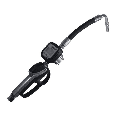
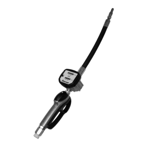
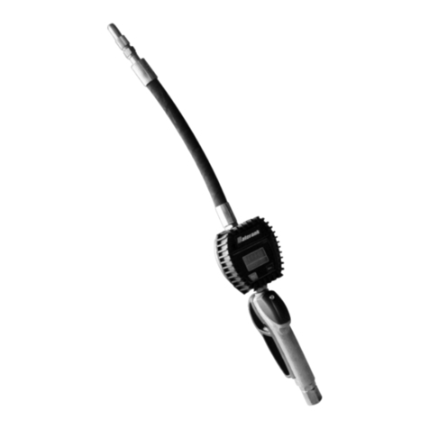
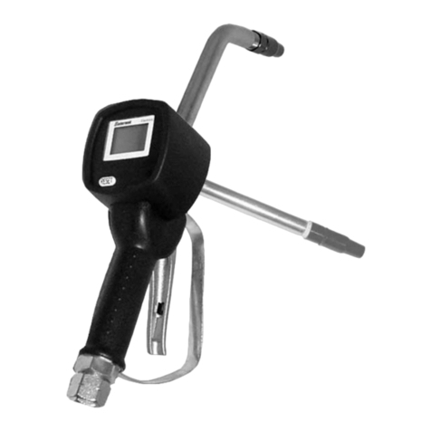
Balcrank 3331-014 Instruction Manual

Thoroughly read and understand this manual before
installing, operating or servicing this equipment.
OPERATION, INSTALLATION,
MAINTENANCE AND REPAIR GUIDE
SERVICE BULLETIN SB3021
Rev. H 10/08
P-SET ELECTRONIC
PRESET CONTROL HANDLE
Model 3331-014
(with Semi-Automatic Tip)
Model 3331-020
(with Flex Extension &
Semi-Automatic Tip)
Model 3331-012
(Bare)
®

2
General Description
This manual assists you in operating and
maintaining your new P-SET Electronic Preset
Control Handle. The information contained will
help you ensure many years of dependable
performance and trouble free operation.
Please take a few moments to read through
this manual before installing and operating
your new control handle. If you experience
problems with this product, refer to the trouble
shooting sections of this manual. If you require
further assistance please contact your local
Balcrank®distributor or Balcrank®authorized
service center.
General Safety
Thoroughly read and understand this manual
before installing, operating or servicing the
described products.
WARNING
!
DANGER: Not for use with uids
t that have a ash point below
100°F (38°C). Examples:
gasoline, alcohol. Sparking could result in an
explosion which could result in death.
Because this control handle can
be incorporated into a pressurized
systems, the following safety
precautions should be observed.
Check equipment regularly and repair or
replace worn and damaged parts.
Never alter or modify any parts of this control
handle, doing so may cause damage to the
control handle and/or personal injury.
Under no circumstances should the dispensing
valve be aimed at any person at any time.
Personal injury may result.
Release pressures built up in the system
before any service or repair is begun. See the
pressure relief procedure below.
Do not operate this control handle above the
maximum operating pressure of 1500 psi.
Always read and follow the uid manufacturer’s
recommendations regarding the use of
protective eye wear, clothing and respirators.
IMPORTANT
!
Pressure Relief Procedure:
Follow this procedure whenever you shut off
the pump, when checking or servicing any part
of the system and when installing, cleaning or
changing any part of the system.
1) Disconnect the air to the pump.
2) Point dispensing valve away from
yourself and others.
3) Open dispensing valve until
pressure is relieved.
WARNING
!
WARNING
!
A manual tip cannot be used on P-Set control
handle. An auto tip must be used. Use of a
manual tip can result in overpressurization,
which can cause control handle to crack.
WARNING
!
Airborne particles and loud noise hazards.
Wear ear and eye protection.
Do not place your hand or ngers over the
dispensing nozzle and/or aim the nozzle at a
person at any time. Personal injury may result.
WARNING
!

3
Specications
Accuracy: + - 0.5% (of Reading)
Flow Range: 0.26 – 8 gal/min
Maximum Operating Pressure: 1,500 PSI
Weight: 2.55 lbs
Inlet: ½” NPT
Outlet: 3/8” NPT (prior to 6/03)
3/8” NPS (after 6/03)
Operating Temperature: 320– 1220F
Wetted Parts: Aluminium, Acetal, Steel, Nitrile Rubber
Fluid Compatibility: Engine Oil, Diesel Oil, Automatic Transmission Fluid,
Anti-freeze
Pressure Loss: 14.4PSI at 3.2 US gal/min with calibration uid
(6 Centipoise viscosity) without extension.
Dimensions: 10 inch Long x 3.7 inch Wide, 4.33 inch High
(Dimensions without extension)
Assembly
Use Teflon®tape (or suitable thread sealant) when
connecting the control handle to the hose connection.
Outlet Extension
The outlet extension can be tted either inline (forward) or
on the outlet port “pistol style” located under the meter.
Note: The threaded plug removed from the outlet port on
the underside of the meter, is used to seal the outlet port
not in use.
Handle Operation
To latch the handle, press the lever, push the button and
then release the lever.
To release the latch, in manual or automatic mode, simply
press and release the lever.
When the control handle is in automatic mode the lever will
release automatically once the preset volume has been
dispensed.
WARNING
!
A manual tip cannot be used on P-Set control
handle. An auto tip must be used. Use of a
manual tip can result in overpressurization,
which can cause control handle to crack.
Meter Introduction
Operating mode description.
Sleep Mode: To minimize battery consumption the meter will
revert to sleep mode if left idle for more than 2 minutes, and
will automatically “power up” when the reset button is pressed
or there is ow through the meter.
Manual Mode: For manual operation. No status segments
displayed.
Auto Mode: For auto shut off operation Batch Display ash-
ing.
Reset Mode: Displays the re-settable accumulative total.
Setting Mode: Provides access to meter settings.
a) Change Preset volumes.
b) Unit settings. (gallons liters, etc.).
c) Options setting.
d) Calibration. (Factory setting).
Batch Display
Total / Status
Low Battery
Batch Display
Total / Status
Low Battery

4
Operation of Buttons
The control buttons can be used in two ways
1) Press: Press & release the button.
2) Double click: Press & release the button twice
quickly.
Totalizers
There are three totalizers built in to your meter
1) Reset batch total: To reset batch total press the reset
button.
2) Non-reset accumulative total: This is located below
the batch total and displays the total volume the meter
has dispensed.
3) Reset accumulative total: Is hidden from view and is
used to track daily, weekly, or monthly usage.
To View or Reset Total
a) If not in manual mode, press and hold the reset
button for approximately 5 seconds to return to
manual mode (no status segment visible)
b) Double click the reset button (the display will enter
the reset total mode)
c) To reset total, press and hold the reset button (3
seconds) until the total zeros.
d) The display will automatically return to manual
mode after 5 seconds, or alternatively double click
the reset button.
Manual Operation
Pull the control handle lever to control oil ow throughput,
opening or closing the lever will vary ow rate.
Auto Mode
In auto mode the meter can be programmed to automatically
shut-off after having dispensed the preset volume.
Presetting Dispense Volume
Press auto button (The display will ash and read the last
volume dispensed)
1) To change volume, press the 10, 1 or 0.1 buttons
to enter the required volume.
2) To dispense the preset volume press lever and
latch.
3) To reset the volume to zero press reset.
Pre-Programmed Volume
1) Press the auto button. Each press of the auto button
will cycle through the ve preset volumes.
2) Stop at the required volume, press and latch lever.
NOTE: The P-SET Electronic control handle automatically
shuts off at the preset volume.
Change Pre-Programmed Volume
A) If in maunal mode, press and release the auto button
two times, the status display will now show “PRES 1”
B) Press and release the auto button to cycle through the
ve preset volumes. Stop at the preset volume to be
changed.
C) To change the preset volumes press the 10, 1, or 0.1
buttons to obtain the desired volume.
D) Press and hold the auto button for approximately 5
seconds to store the new volume.
E) To return to manual mode press and hold the reset
button for approximately 5 seconds.
Changing Units
1) Press and hold the reset button until “units” appears.
2) Press the reset button to cycle through the units of
measure.
3) Stop at the desired setting.
Batch Total - Accumulative Total
Liter Liter
Pint Gallon
Quart Gallon
Gallon Gallon
When the desired unit of measure is reached, press and
hold the reset button for approximately 5 seconds to return
to manual mode.
Note: If you do not want to change the options settings
press and hold the reset button for approximately 5 seconds
to return to manual mode.
Factory Settings display mode
1) Displays factory setting and calibration settings.
2) In units setting mode press and hold reset for 10
seonds. After 5 seconds the display will revert to
manual mode and after a further 5 seconds will
change to factory settings display.
3) Pressing reset will cycle through seven parameters.
MODEL = model number
HWREL = Electronics hardware release
SWREL = software release
SEr = serial number
MAnuF = manufacturer number
K FAC = K factor
F CAL = eld calibration factor
4) Press and hold reset for 5 seconds to return to
manual mode.
Diagnostic mode
1) Diagnostics mode is for checking all of the functions
of the module
2) In manual mode press reset and CAL button (to
access the CAL button remove the calibration screw,
item 18 on the parts list then use a small hex key
or other small blunt instrument to press the CAL
button).
3) The display will change to show all segments of the
display on.
4) Pressing reset cycles through
- Diag displays the mark space ratio of the reed
switches
- Eeprom check
- Battery check shows the battery condition 100-
fully charged, 0 – at
5) Pressing auto displays auto and actuates the latch
release motor
6) Pressing 10, 1, 0.1 displays 10, 1, 0.1
7) Pressing cal shows CAL
Options settings
1) Allows options to be set
2) In diagnostic mode press Cal 5 seconds to enter
option mode

5
3) Pressing cal cycles through options
4) Pressing reset cycles through values for each option
5) Pressing and holding reset 5 seconds saves the set-
tings and returns to manual mode.
6) Options are
- Option 1 sleep y/n
- Option2 batch resets to zero on wake y/n
Low Battery
The battery segment will ash when the battery is low
and needs replacing.
The control handle will not operate in auto mode when
the battery is low, although the gun can still be used in
manual mode.
NOTE: When the battery segment starts ashing replace
the battery as soon as possible.
Battery Replacement
1) Remove the protective boot.
2) Remove the battery cover screw located near the inline
(forward) outlet port and remove the battery cover.
3) Replace the two AA Alkaline batteries. (Check + - are
correct)
4) Inspect the battery cover seal for damage and replace
if necessary.
5) Replace battery cover and tighten screw, while press-
ing cover in place.
Error Message
If an error is detected in meter operation, the following error
codes will appear on the display.
Err1 – Sensor error
Err2 – Auto shut off failure
Err3 – Flow rate too high
Err4 – Calibration error
Err5 – Computer error
To reset the meter after an error message press reset.
Note: Lightly lubricate the valve cam before
assembly.
B) Place o-ring (19) onto valve cam (16).
Note: The cutout section in the middle of the
valve cam (16) must face the inlet swivel (31).
C) Replace the valve cam (16) into the body (15).
Note the orientation shown on the assembly
drawing. Fit the second o-ring (19) and washer
(20).
D) Slide lever assembly (34) into position and replace
the two allen screws (32). Use loctite or similar
sealant.
E) Replace plunger (24).
Note: The end hole in the plunger must face the
meter.
F) Assemble the seal/valve body (25, 26) and
spring (27) and replace into the handle body.
Note: Install the spring, small end rst.
G) Replace handle sleeve (28).
H) Replace washer (29), o-ring (25), and swivel
assembly (31) and screw rmly into place. Use
Loctite or similar sealant.
Pressure Relief Procedure:
Follow this procedure whenever you shut off
the pump, when checking or servicing any part
of the system and when installing, cleaning or
changing any part of the system.
1) Disconnect the air to the pump.
2) Point dispensing valve away from
yourself and others.
3) Open dispensing valve until
pressure is relieved.
WARNING
!
Maintenance
Inspect your control handle daily for any signs of
damage. Replace any damaged parts or components as
required.
Handle Disassembly
Use a clean work area to carry out maintenance.
A) Remove the uid hose from the control handle
inlet swivel (31).
B) Unscrew and remove swivel (31), washer (29),
and o-ring (30) from the control handle inlet.
Clean or replace the strainer and o-ring.
CAUTION: The swivel is under spring
tension.
C) Slide off the handle sleeve (28).
D) Remove valve spring (27), seal/valve body
assembly (25,26) and plunger (24).
Lever and Valve Removal
A) Using a 2.5mm allen wrench, remove the two
handle screws (32).
B) Remove lever (34).
C) Remove the washer (20) and o-ring (19), then
push the valve cam (16) from the handle body
(15), and remove o-ring (19).
Handle Reassembly
A) Clean and inspect all parts. Replace any suspect,
worn, or damaged components.
Meter Disassembly
A) Unscrew the swivel assembly (31) two complete
turns to allow easy disassembly and reassembly of
the meter and remove boot (1).
B) Remove battery cover screw (5) and batteries (9).
C) Remove the three screws (11) and the calibration
port screw (18) from the underside of the meter.
D) Carefully remove the computer module (2) from the
module housing (10).
Note: The computer module is non repairable
and will need to be replaced if damaged.
E) Remove the four allen screws (17) from the
underside of the meter and remove the module
housing (10).

6
ELBUORTESUACYDEMER
ehthguorhtgnissapdiulfoN
retem
reniartsdekcolB.AreniartsecalperronaelC.A
srotorehtgnimmajselcitraptriD.B naelcdnaylbmessaretemeltnamsiD.B
laesregnulpdegamaD.ClaesregnulpdegamadecalpeR.C
gniretsigertonsiretemehT
tuptuodiulf
yrettabdaeD.AyrettabecalpeR.A
stengamehtmorflangisoN.BstengamkcehC.B
eludomretupmocdegamaD.CeludomretupmocecalpeR.C
1rrEsdaeryalpsidreteM rorrerosneS fI(retupmocehtteserotnottubte
serehtsserP
ehtnistengamehtkcehc,staeperrorreeht
)rotor
3rrEsdaeryalpsidreteM hgihootetarwolF nim/lagSU8-62.0otetarwolfehttsujdA
metsysehtmorfriaetanimilE
4rrEsdaeryalpsidreteM rorrenoitarbilaC retupmocehtteserotnottubteserehtsserP
5rrEsdaeryalpsidreteM rorreretupmoC retupmocehtteserotnottubteserehtsserP
pitehtmorfkaelliotnatsnoClaesregnulpdegamaD )egamadrofkcehc(laesregnulpecalpeR
pitehtmorfpirdtnettimretnIpiteht
nitriD ,selcitraptridynatuowolbdnapitehtevomeR
yrassecenfiecalper
revelehtmorfkaelliO
aeraylbmessa
sgnir-odegamaDsgnir-odegamadecalpeR
ehtneewtebmorfkaelliO
ehtdnagnitsacydob
gnitsaceludomretupmoc
sgnir-odegamaDsgnir-odegamadecalpeR
etarwolfwoLreniartsdekcolBreniartsecalpeR
telnileviwsehtmorfgnikaelliOleviwsrognir-odegamaDleviwsrognir-oecalpeR
Meter Reassembly
A) Clean and inspect all parts. Replace any suspect,
worn, or damaged components.
B) Replace rotors (13).
Note: Ensure the rotor with the magnets is
assembled with the magnets facing up and
positioned on the correct side of the meter. Both
rotors must also be positioned at 90 degrees to each
other.
C) Replace the handle body o-ring (14).
D) Carefully position the module housing, (10) on top of
the handle body (15), replace and tighten the four
allen screws (17).
E) Test the control handle for correct operation.
F) Replace the computer module (2).
G) Replace and tighten the three phillips head
screws (11) and calibration port screw (18).
H) Replace the two AA Alkaline batteries (9). Use the
directions on the label found inside the battery
housing for correct battery orientation.
I) Replace battery cover assembly (6, 7, and 8)
and tighten the screw (5).
J) Firmly tighten the swivel assembly (31).
K) Replace the boot (1).
L) Test the control handle for correct operation.
Field Calibration
1) Field calibration allows a +_5% adjustment of
the calibration.
2) In Options mode press cal 5 seconds. Current
eld calibration factor will be displayed 95-105
3) To reset the factor to 100
4) Press CAL 5 seconds F CAL ashes. (to access
the CAL button remove the calibration screw, item
18 on the parts list then use a small hex key or other
small blunt instrument to press the CAL button).
5) Press CAL and reset
6) To calibrate press cal 5 seconds fcal ashes
7) Dispense a volume 5-20L
8) Measure the dispensed volume
9) Enter the actual volume into the meter
NOTE: Auto version use 10, 1, 0.1 buttons and
Auto to adjust 0.01 value
NOTE: Single button version press cal cycles
through digits press reset adjusts selected digit.
10) To calculate new factor press and hold cal 5
seconds. Display will show new eld calibration
factor
11) Replace the calibration screw when complete.
Troubleshooting

7
P-Set Electronic Preset Control Handle Parts List
Control Valve Service Kit
(Order 900013)
* Prior to 7/03 (stamped on handle 0283) use metal washer.
After 7/03 (stamped on handle 0293) use plastic washer.
Item Part No. Qty. In Kit Description Item Part No. Qty. In Kit Description
1 830727 1 - Boot, P-Set 21 - 1 - Latch Plate Assembly
2 830726 1 - Module, P-Set 22 - 1 - Latch Pivot Pin
3 - 2 - Screws 23 - 1 - Spring
4 - 1 - Latch Release Assembly 24 - 1 - Plunger
5 - 1 - Battery Cover Screw 25 - 1 Seal
6 - 1 - O-Ring 26 - 1 - Valve Body
7 - 1 - Battery Cover 27 - 1 Valve Spring
8 - 1 - O-Ring 28 - 1 - Handle Sleeve
9 - 2 - AA Alkaline Batteries 29 - 1 - Washer
10 - 1 - Module Housing 30 - 1 - O-Ring
11 - 3 - Screws 31 830728 1 - Swivel, Control Handle
12 - 2 - Magnets 32 - 2 Screws
13 - 2 - Oval Gear Set 34 - 1 - Lever Latching
14 - 1 - O-Ring 35 - 1 - Button Spring
15 - 1 - Control Handle Body 36 - 1 - Lever Plug
16 - 1 - Valve Cam 37 - 1 Mesh
17 - 4 - Screws 38 - 1 O-Ring
18 - 1 - Calibration Screw 39 3332-
032
1 - Semi-Automatic Tip (not
shown) (prior to 6/03)
19 - 2 O-Ring 40 3332-
045
1 - Semi-Automatic Tip
(after 6/03)
20 - 1 Washer*

Balcrank®Corporation
Weaverville, NC 28787
800-747-5300
800-763-0840 Fax
www.balcrank.com
Distributed by:
SERVICE BULLETIN SB 3021
Rev. H 10/08
830351
Revision Log:
Rev. E - changed to NPS thread at outlet.
Rev. F - Added note about washer (item 20).
Rev. G - Added Calibration Procedure.
Rev. H - Updated operation instructions. and
added model 3331-020
Balcrank Lubrication Equipment Warranty Statement
All Balcrank equipment sold by authorized Balcrank distributors is warranted to their original customer to be free from defects in materials and workmanship
for a period of one year from the date of sale to that customer. Selected Balcrank equipment carries warranty terms for a more extended period as dened in
the Balcrank Lubrication Equipment & Accessories User Price List, wherein a “lifetime” warranty represents a warranty period of thirty years. Within the initial
one-year warranty period, Balcrank will repair or replace all Balcrank equipment determined by Balcrank to have defective materials or workmanship. For
equipment carrying more extended warranties, Balcrank will repair or replace the product including parts and labor during the rst full year and will provide
parts only for the remainder of the warranty period.
This warranty applies only to equipment installed and operated according to applicable Balcrank Service Bulletins and Installation Instructions.
Any equipment claimed to be defective must be returned, freight prepaid, to an Authorized Balcrank Service Center (ASC). Upon receiving candidate warranty
equipment from a customer, ASC will: 1) diagnose to determine the warrantable condition of the equipment, 2) submit, prior to repair or replacement, a
request to Balcrank for warranty authorization, then 3) in cooperation with Balcrank, proceed with repair locally or forward the equipment to Balcrank and
obtain replacement. If the part(s) or equipment items are found defective upon inspection by Balcrank, they will be repaired or replaced, and then will be
returned to the ASC. If Balcrank nds the claimed part(s) or equipment not to be defective, the ASC will receive written authorization from the original
customer, and then repair them for a reasonable charge to the customer, which will include all applicable parts, labor, and return transportation costs.
Optionally, the customer may submit certain eligible products directly to Balcrank for warranty return by using Balcrank Lubrication Equipment Direct Service
Warranty Procedure. Eligible products are dened in the Balcrank Lubrication Equipment & Accessories User Price List. Refer to the Balcrank web site www.
balcrank.com for a copy.
Any equipment returned to Balcrank must have the Warranty Service Claim number (WSC#) clearly marked on the outside of the carton. Balcrank’s sole
responsibility is for defects in material and workmanship, and Buyer’s sole and exclusive remedy hereunder, shall be limited to repair or replacement of the
defective part or equipment.
This warranty does not cover, nor shall Balcrank be liable for repair or replacement of parts or equipment resulting from general wear and tear through use,
or damage or failure caused by improper installation, abuse, misapplication, abrasion, corrosion, insufcient or improper maintenance, negligence, accident,
alteration, or substitution of non-Balcrank parts.
Furthermore, the Warranty for Lubrication Equipment and Accessories does not cover the following specic conditions:
• Failure or damage to equipment caused by dirt or debris in compressed air lines and uid lines. This includes, but is not limited to, clogged inlet lters,
strainers, or regulators; uid meters; control handles; uid tips; and valves.
• Failure of normal wear parts including but not limited to: o-rings, packings, seals and valves unless originally improperly installed by the
factory.
• Products placed in applications for which their use was not intended. Examples include but are not limited to Lubricant pump being used
to pump solvents, or placing equipment intended strictly for indoor use outdoors
• Damage to equipment resulting from operation above and beyond Balcrank’s recommendations.
• Leaks at air and uid ttings and connections.
• Damage caused by thermal expansion whenever adequate pressure relief was not included in the system.
• Loose suction tubes on pumps.
• Incorrect hose reel spring tension, requiring adjustment.
THERE ARE NO OTHER WARRANTIES, EXPRESSED OR IMPLIED, INCLUDING WARRANTIES OF MERCHANTABILITY OR FITNESS FOR A
PARTICULAR PURPOSE. IN NO EVENT SHALL BALCRANK BE LIABLE FOR ANY SPECIAL, CONSEQUENTIAL, OR OTHER DAMAGES OF SIMILAR
NATURE, INCLUDING BUT NOT LIMITED TO LOST PROFITS, LOST PRODUCTION, PROPERTY DAMAGE, PERSONAL INJURY, WHETHER SUFFERED
BY BUYER OR ANY THIRD PARTY, IRRESPECTIVE OF WHETHER CLAIMS OR ACTIONS, LEGAL OR EQUITABLE, FOR SUCH DAMAGES ARE BASED
UPON CONTRACTS, WARRANTY, NEGLIGENCE, STRICT LIABILITY, OR OTHERWISE. ANY CLAIM OR ACTION FOR BREACH OF WARRANTY MUST
BE BROUGHT WITHIN TWO (2) YEARS FROM THE DATE OF SALE TO THE ORIGINAL CUSTOMER.
This manual suits for next models
2
Table of contents
Other Balcrank Controllers manuals
Popular Controllers manuals by other brands

Siemens
Siemens SINAMICS PM240-2 Hardware installation manual

Bodine
Bodine Quality IN Motion 0810 Instructions for installation and operation

AEMT
AEMT TIME MARK 4082 manual

Smartgen
Smartgen HAT553V user manual

Grundfos
Grundfos DPC CSIR Installation & operating instruction

PlugTech
PlugTech MBC-DPIQ operating instructions