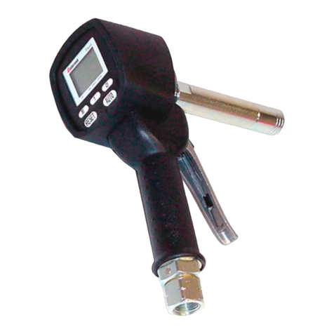
Balcrank 3330-142 Instruction Manual

In-Line Electronic
Control Handle
Thoroughly read and understand this manual before
installing, operating or servicing this equipment.
Operation, Installation,
Maintenance and Repair Guide
Model # 3330-142
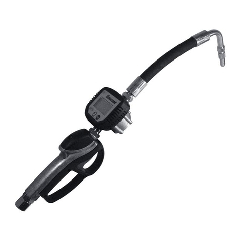
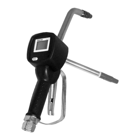
Rigid Extension
Model # 3330-144
Flex 90 Extension
Model # 3330-143
Flex Extension
(shown)
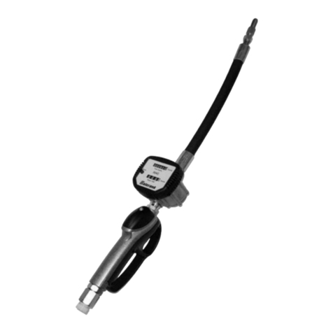
Model # 3120-067
In-Line Meter
(shown)
SERVICE BULLETIN SB 3070
Rev. A 2/10
®

PRODUCT DESCTIPTION
The In-Line Electronic Control Handle is designed specically
to dispense motor oils, automatic transmission uid, antifreeze
(Glycol) and antifreeze/water soulution. Perfect balance,
lightweight, ruggedness, and comfortable grip make it the
best choice for overhead reel systems.
The electronic register module can be programmed to
dispense in pints, quarts, liters, or gallons and will totalize in
liters or gallons. A calibration factor and unit of measure are
programmed during factory test. A 5-digit liquid crystal display,
accurate to the third decimal place, shows the exact amount
of uid dispensed.
Caution:
1) Always read and follow the uid manufacturers’s
recommendations regarding the use of protective
eye wear, clothing, gloves, and other personal
equipment.
2) Never alter or modify any parts of this product;
doing so may cause damage and/or personal
injury.
!
Do not place your hand or ngers over the
dispensing nozzle and/or aim the nozzle at
a person at any time. Personal injury may
result.
WARNING
!
GENERAL SAFETY
Always use the following
Pressure Relief Procedure
whenever shutting off, cleaning, or
in any way checking or servicing the control handle:
1) Disconnect compressed air line or turn off power
supply at the uid pump.
2) Point the control handle outlet into a waste
container and open trigger to relieve pressure.
3) Open any bleed-type supply air valves and uid
drain valves in the system.
4) Leave the drain valves open until you are ready to
re-pressurize the system.
WARNING
!
WARNING
!
DANGER: Not for use with uids that
have a ash point below 100°F ( 38°C,
examples: gasoline, alcohol). Sparking
could result in an explosion which could
result in death.
IMPORTANT
!
Read these safety warnings
and instructions in this manual
completely, before installation
and start up of the control
handle. It is the responsibility
of the purchaser to retain this manual for reference.
Failure to comply with the recommendations stated in
this manual will damage the control handle and void
factory warranty.
WARNING
!
Airborne particles and loud noise
hazards.
Wear ear and eye protection.
!
Maximum Fluid Pressure 1000 PSI. Under no
circumstances should the control handle be
aimed at any person or your own body at anytime.
Personal injury may result.
CAUTION
TABLE OF CONTENTS
Cover..................................................................................1
General Safety........................................................................2
Product Description............................................................2
Technical Specications.....................................................3
Operation......................................................................3 - 4
Conguration......................................................................4
Calibration......................................................................4 - 6
Maintenance...................................................................6 - 7
Parts List.............................................................................7
Troubleshooting...................................................................7
Warranty..............................................................................8

MODES OF OPERATION
Normal mode is the standard dispensing mode. While
the meter is counting, the batch and resettable totals are
displayed at the same time (see Figure 3 below).
If one of the keys is accidentally pressed it has no effect on
dispensing or the batch or resettable totals. A few seconds
after dispensing is complete, the lower totalizer will switch
from the resettable total to the non-resettable total. The word
reset above the word total disappears, and the resettable total
is replaced by the non-resettable total in the display (See
Figure 4 below). This is called standby mode and remains
on the display while the meter is not in use.
Batch Totalizer Reset
The batch totalizer can be reset by pressing the RESET to
zero button when the meter is in standby mode, meaning
when the the word “TOTAL” is in the display (See Figure 5
below).
Once the reset button has been pressed, all digits in the
display will momentarily light up (See Figure 6 below) and
then the display will blank out momentarily. When the display
comes back on, the batch total and the resettable totals will
be shown in the display (See Figure 7). After approximately
5 seconds the resettable total will revert to standby mode
(See Figure 8).
Figure 3 Figure 4
Figure 5 Figure 6
Figure 7 Figure 8
Resetting the Resettable Total
The resettable total can only be reset after resetting the batch
totalizer. To reset the resettable total, press the RESET button
once to reset the batch total. When the display comes back
on (See Figure 7 above), press and hold the RESET button
until all digits in the display light up then blank out momentarily.
When the display re-illuminates, the resettable total will read
0.0 (See Figure 9).
OPERATION
Depressing the Reset to zero button before each use resets
the batch totalizer to zero. Squeeze the trigger handle to
dispense the uid. The re-settable totalizer is displayed when
the reset to zero button is pressed. After approximately 5
seconds the non-resettable totalizer is displayed in the lower
right. If the units dispensed are pints, quarts, or gallons, the
totalizers will read in gallons. If the units dispensed are liters,
the totalizers will read in liters.
DISPLAY FUNCTIONS
Calibr. Button
The Calibr. button is used to enter calibration mode as well as
other functions described in the conguration and calibration
sections of this service bulletin.
Reset to zero Button
The Reset to zero button is used to reset the Batch Total
and to reset the re-settable total as well as other functions
described in the conguration and calibration sections of this
service bulletin.
12.345 QT
12.3 TOTAL
GAL
88.8.8.8 QT
PT
L
GAL
Cal 88888.8
F L OW R AT E
RES ET
TOTAL
x100
L
GAL
BAT
0.0000 QT
12.3 RE S ET
TO TAL
GAL
0.0000 QT
12.3 TOTAL
GAL
12.345 QT
12.3 TOTAL
GAL
12.345 QT
12.3 RE S ET
TO TAL
GAL
TECHNICAL SPECIFICATIONS
Accuracy (after eld calibration)..............................+/- 0.5%
Flow range..................................................0.25 - 7 Gal/min.
Max operating pressure...........................................1000 psi
Weight (meter only)..................................................1.55 lbs
Inlet.......................................................1/2” NPT compatible
Outlet....................................................1/2” NPT compatible
Operating Temp. Range....................................320F - 1400F
Fluid compatibility...............Oils (up to SAE 240), ATF,
Antifreeze (Glycol), Antifreeze/
water solution

CALIBRATION
It is highly recommended to perform meter calibration before
the rst use of the meter. The meter allows for precise
calibration by modifying the calibration factor (k factor).
To display the current k factor, press and hold the CALbutton
when the display is in standby mode and the current k factor
will be displayed. If the k factor has never been modied,
the factory k factor is displayed. If you are using the meter
with the “factory k factor”, the display will appear as shown
(See Figure 11 below).
If the k factor has been modied, the word “USER” will appear
in the display below the k factor (See Figure 12 below).
There are two ways to perform calibration of the meter:
- Field calibration, performed by dispensing
while in “Field” calibration mode.
- Direct calibration, performed by directly
modifying the calibration factor.
Figure 11
Figure 12
NOTE
!
For proper calibration is is important to:
- completely eliminate air from the system
- use an accurate sample container not less than
5 quarts
- during calibration, ensure dispensing is done at
a contant ow rate equivalent to normal
dispensing until the container reaches the 5
quart mark. You may start and stop the ow but
do not “trickle” ow
- after dispensing wait a short period to ensure
any air bubbles have dissipated
1.0000 QT
fact GAL
Cal
0.9998 QT
user GAL
Cal
Figure 9
CONFIGURATION - Unit of Measure
The meter has four possible combinations of units of measure
that can be set based on the table below.
Batch Totalizer Totals Register
Liters (L) Liters (L)
Gallons (Gal) Gallons (Gal)
Quarts (Qt) Gallons (Gal)
Pints (Pt) Gallons (Gal)
To change between these combinations, the meter
must be in standby mode (See Figure 5). With the
meter in standby mode, press and hold the
RESET and CAL buttons simultaneously. The word “Unit”
will appear in the display. You can then change the unit of
measure by pressing the RESET button until the desired
combination of units of measure is displayed. To save the
new unit of measure, press and hold the CAL button. The
meter will momentarily show all of the display digits lit up
(See Figure 6), will go through its startup cycle then will go
to standby mode.
0.0000 QT
0.0 R E S ET
TO TA L
GAL

Action Meter Display
1
Meter in standby mode
2
Press & hold CAL
button, current k factor
is displayed. The
words “FACT” and
“USER” indicate which
of the two factors is
currently in use.
3
Press & hold RESET
button. Meter enters
FIELD calibration
mode.
4
Dispense into sample
container. Dispensing
can be interrupted and
started again at will.
Continue dispensing
until the level of the
uid in the sample con-
tainer has reached the
graduated area. There
is no need to reach a
preset quantity.
Indicated value
Actual
Value
5.0
1
2
3
4
5
Field Calibration
The table below lists the steps for Field calibration.
5
Press the RESET until
an “up” arrow appears
in the bottom left of the
display. In the exam-
ple, the meter value is
below the actual value.
Press the CAL button
to adjust the meter
value to match the
actual value. You may
either press & release
the CAL button which
will advance the meter
value by one or press &
hold the CAL button for
more rapid adjustment.
If the meter value is
higher than the actual
value, press & release
the RESET button
again and the “up”
arrow will change to
a “down” arrow. You
can then use the CAL
button to lower the
meter value. If you
go over (or under) the
desired value while
adjusting the meters
k factor, press and
release the RESET
button again to change
the arrow direction.
6
Once the k factor has
been adjusted to match
the actual value, press
and hold the RESET
button to end calibra-
tion. This stores the
new k factor, which will
be displayed momen-
tarily after which the
meter will return to
standby mode.
Direct Modication of k factor
Direct modication of the k factor is useful to correct a “mean
error” based on serveral dispenses. If normal meter operation
shows a mean percentage error, this can be corrected by
applying a percentage correction factor to the current k factor.
The percentage correction of the k factor must be calculated
using the formula below:
New k factor = Old k factor x
Example:
Error percentage found E% -0.9%
Current k factor 1,000
New User k factor 1,000 * [(100-(0,9))/100]=
1,000 * [(100+0,9)/100]=1,009
100 –E%
100
()
1.0000 QT
fact GAL
Cal
0.0000 QT
field
Cal
4.9400 QT
field
Cal
4.9400 QT
field
Cal
4.9400 QT
field
Cal
- - - - QT
end
Cal
1.060 QT
end
Cal
0.0000 QT
12.3 GAL
TO T AL

BATTERY REPLACEMENT
To change the batteries:
- Press the RESET button to update all totals
- Remove the screws on from the battery cover
- Remove the cover
- Remove the old batteries
- Place new batteries in the meter (2 x AAA Alkaline)
* Always replace both batteries at the same time
* Conrm that the batteries are in the correct
position
- Replace the cover and screws
- Press the Reset to zero button and the meter will switch
on, normal operation can now be resumed
The meter will display the same Resettable Total, the same
Total and the same Batch indicated before the batteries were
changed. After changing the batteries the meter does not
need to be recalibrated.
MAINTENANCE
The meter is designed to be virtually maintenance free. The
only maintenance required is periodic battery replacement
and cleaning of the uid chamber if a reduction in ow is
observed.
The meter comes complete with two 1.5 V size AAA alkaline
batteries. The function of the low-battery alarm is shown in
the table below.
Alarm Meter Display
1
When the battery
voltage falls below the
operational level, “BAT”
appears on the display.
In this condition, the
meter will continue to
operate correctly but it
is advisable to replace
the batteries as soon
as possible.
12.345 QT
12.3 TO TA L
GAL
BA T
Action Meter Display
1
Meter in standby mode
2
Press & hold CAL
button, current k factor
is displayed
3
Press & hold RESET
button. Meter enters
FIELD calibration
mode.
4
Press & hold the
RESET button a
second time. Meter
enters DIRECT calibra-
tion mode. The current
k factor is displayed &
an “up” arrow appears
in the lower left of
the display. Press &
release the CAL button
to increase the k factor
(negative error). If the
k factor needs to be
decreased (positive
error), press & release
the RESET button to
change to the “down”
arrow.
5
Once the k factor has
been adjusted to match
the actual value, press
and hold the RESET
button to end calibra-
tion. This stores the
new k factor, which will
be displayed momen-
tarily after which the
meter will return to
standby mode.
NOTE: Replacing the batteries will not affect the
k factor.
If the meter indicates less than the actual amount dispensed
(negative error), the new k factor must be higher then the
old k factor as shown in the example. The opposite applies
if the meter shows more than the actual amount dispensed
(positive error).
The table below lists the steps for Direct modication of the
k factor.
1.0000 QT
fact GAL
Cal
0.0000 QT
12.3 GAL
TO T AL
0.0000
FIELD
Cal
1.0000
DIRECT
Cal
1.0000
DIRECT
Cal
- - - - QT
end
Cal
1.009
END
Cal
BATTERY REPLACEMENT

Always use the following
Pressure Relief Procedure
whenever shutting off, cleaning, or
in any way checking or servicing the control handle:
1) Disconnect compressed air line or turn off power
supply at the uid pump.
2) Point the control handle outlet into a waste
container and open trigger to relieve pressure.
3) Open any bleed-type supply air valves and uid
drain valves in the system.
4) Leave the drain valves open until you are ready to
re-pressurize the system.
WARNING
!
Follow the steps below for cleaning the uid chamber.
- Remove the four screws from the back cover.
- Remove the cover then remove the oval gears make note
of the position/orientation of the oval gears.
- Clean the chamber and the gears carefully using a soft
brush.
- Replace the oval gears (ensure they are re-installed in the
position/orientation in which they were removed).
- Replace the cover and install the screws.
TROUBLE POSSIBLE CAUSE REMEDY
Faded Display Weak batteries Replace batteries
No reading in display Dead batteries Replace batteries
Meter has not been reset after
battery replacement
Press the Reset to zero button
Damaged meter Replace meter
The meter is not accurate Wrong calibration factor Calibrate the meter
Flow rate is above or below the
operational ow range
Increase or decrease the ow
rate.
Display is on but meter does not
count
Gears placed incorrectly after
cleaning the uid chamber
Reposition the gears
Damaged meter Replace meter
Reduced or no ow Clogged gears Clean the uid chamber
Blocked strainer Clean or replace strainer
Leaking nozzle (tip) Damaged seals Replace the nozzle (tip)
Oil leak from trigger area Damaged seals Replace the grip
Oil leak from inlet swivel Damaged O-ring or swivel Replace the grip
TROUBLESHOOTING GUIDE
CLEANING THE FLUID CHAMBER
REMOVING BACK COVER & OVAL GEARS
4
3
5
12
ITEM PART # DESCRIPTION
1829482 Grip
2832863 Digital Meter
3832190 Rigid Extension
4831789 Flex 90 Extension
5 832199 Flex Extension
PARTS LIST

Balcrank®Corporation
Weaverville, NC 28787
800-747-5300
800-763-0840 Fax
www.balcrank.com
SERVICE BULLETIN SB3070
Rev. A 2/10
Distributed by:
Balcrank Lubrication Equipment Warranty Statement
All Balcrank equipment sold by authorized Balcrank distributors is warranted to their original customer to be free from defects in materials and workmanship
for a period of one year from the date of sale to that customer. Selected Balcrank equipment carries warranty terms for a more extended period as dened in
the Balcrank Lubrication Equipment & Accessories User Price List, wherein a “lifetime” warranty represents a warranty period of thirty years. Within the initial
one-year warranty period, Balcrank will repair or replace all Balcrank equipment determined by Balcrank to have defective materials or workmanship. For
equipment carrying more extended warranties, Balcrank will repair or replace the product including parts and labor during the rst full year and will provide
parts only for the remainder of the warranty period.
This warranty applies only to equipment installed and operated according to applicable Balcrank Service Bulletins and Installation Instructions.
Any equipment claimed to be defective must be returned, freight prepaid, to an Authorized Balcrank Service Center (ASC). Upon receiving candidate warranty
equipment from a customer, ASC will: 1) diagnose to determine the warrantable condition of the equipment, 2) submit, prior to repair or replacement, a
request to Balcrank for warranty authorization, then 3) in cooperation with Balcrank, proceed with repair locally or forward the equipment to Balcrank and
obtain replacement. If the part(s) or equipment items are found defective upon inspection by Balcrank, they will be repaired or replaced, and then will be
returned to the ASC. If Balcrank nds the claimed part(s) or equipment not to be defective, the ASC will receive written authorization from the original
customer, and then repair them for a reasonable charge to the customer, which will include all applicable parts, labor, and return transportation costs.
Optionally, the customer may submit certain eligible products directly to Balcrank for warranty return by using Balcrank Lubrication Equipment Direct Service
Warranty Procedure. Eligible products are dened in the Balcrank Lubrication Equipment & Accessories User Price List. Refer to the Balcrank web site www.
balcrank.com for a copy.
Any equipment returned to Balcrank must have the Warranty Service Claim number (WSC#) clearly marked on the outside of the carton. Balcrank’s sole
responsibility is for defects in material and workmanship, and Buyer’s sole and exclusive remedy hereunder, shall be limited to repair or replacement of the
defective part or equipment.
This warranty does not cover, nor shall Balcrank be liable for repair or replacement of parts or equipment resulting from general wear and tear through use,
or damage or failure caused by improper installation, abuse, misapplication, abrasion, corrosion, insufcient or improper maintenance, negligence, accident,
alteration, or substitution of non-Balcrank parts.
Furthermore, the Warranty for Lubrication Equipment and Accessories does not cover the following specic conditions:
• Failure or damage to equipment caused by dirt or debris in compressed air lines and uid lines. This includes, but is not limited to, clogged inlet lters,
strainers, or regulators; uid meters; control handles; uid tips; and valves.
• Failure of normal wear parts including but not limited to: o-rings, packings, seals and valves unless originally improperly installed by the
factory.
• Products placed in applications for which their use was not intended. Examples include but are not limited to Lubricant pump being used
to pump solvents, or placing equipment intended strictly for indoor use outdoors
• Damage to equipment resulting from operation above and beyond Balcrank’s recommendations.
• Leaks at air and uid ttings and connections.
• Damage caused by thermal expansion whenever adequate pressure relief was not included in the system.
• Loose suction tubes on pumps.
• Incorrect hose reel spring tension, requiring adjustment.
THERE ARE NO OTHER WARRANTIES, EXPRESSED OR IMPLIED, INCLUDING WARRANTIES OF MERCHANTABILITY OR FITNESS FOR A
PARTICULAR PURPOSE. IN NO EVENT SHALL BALCRANK BE LIABLE FOR ANY SPECIAL, CONSEQUENTIAL, OR OTHER DAMAGES OF SIMILAR
NATURE, INCLUDING BUT NOT LIMITED TO LOST PROFITS, LOST PRODUCTION, PROPERTY DAMAGE, PERSONAL INJURY, WHETHER SUFFERED
BY BUYER OR ANY THIRD PARTY, IRRESPECTIVE OF WHETHER CLAIMS OR ACTIONS, LEGAL OR EQUITABLE, FOR SUCH DAMAGES ARE BASED
UPON CONTRACTS, WARRANTY, NEGLIGENCE, STRICT LIABILITY, OR OTHERWISE. ANY CLAIM OR ACTION FOR BREACH OF WARRANTY MUST
BE BROUGHT WITHIN TWO (2) YEARS FROM THE DATE OF SALE TO THE ORIGINAL CUSTOMER.
Revision Log:
Rev. A - Release 2/10
This manual suits for next models
3
Table of contents
Other Balcrank Controllers manuals
Popular Controllers manuals by other brands

Newport
Newport SMC100CC user manual

Titan Controls
Titan Controls Helios 10 instruction manual

Emerson
Emerson Dixell XRi60CH Installing and operating instructions

Magnetek
Magnetek SBN Series instruction manual

Reflex
Reflex Reflexomat RS 90/1 operating manual

Bug-O Systems
Bug-O Systems AVC-2100 Series Instructions and parts manual