manuals.online logo
Brands
  1. Home
  2. •
  3. Brands
  4. •
  5. Bamo
  6. •
  7. Measuring Instrument
  8. •
  9. Bamo IER Turbicube 20 User manual

Bamo IER Turbicube 20 User manual

OPERATING INSTRUCTIONS
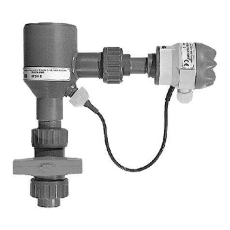
Turbidity measuring TURBICUBE
BAMO IER GmbH Pirnaer Straße 24 D-68309 Mannheim
Tel. +49 (0)621 84224-0 Fax: +49 (0)621 84224-90 www.bamo.de [email protected]
SU3332a.doc 01/13 1
Installation, initial start-up and maintenance may only be performed by trained personnel! All applicable
European and national regulations regarding installation of electrical equipment must be adhered to.
The device may only be connected to supply power which complies with the specifications included in the
technical data and on the serial plate!
The device must be disconnected from all sources of power during installation and maintenance work!
The device may only be operated under the conditions specified in the operating instructions!
Functions Description:
The turbidity measuring device determines the turbidity of liquids using the light absorption and scattered light
measuring method.
The inline measuring cell at the sensor set makes use of two IR transmitters and one IR receiver in pulsating light
mode (IR measuring method according ISO 7027).
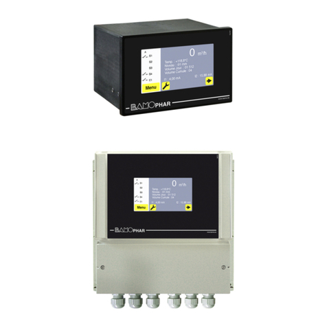
The interconnected BAMOPHOX TUR measuring amplifier analyses the 4 to 20 mA signal generated by the sensor
set.
Installing the Sensor Fixture:
Observe:
The fixture must be installed vertically!
Best installation is the mounting in a ascending tube with slow down section 600 mm in front and 400
mm behind the turbidity measuring device
The sensor fixture must be completely filled with liquid medium during the performance of measurements.
Install to the vertical portion of a siphon trap if necessary.
Air bubbles distort measurement results.
Glasses must be clean – clean at regular intervals as required.
Safety Precautions:
OPERATING INSTRUCTIONS
Turbidity measuring TURBICUBE
BAMO IER GmbH Pirnaer Straße 24 68309 Mannheim
Tel. +49 (0)621 84224-0 Fax: +49 (0)621 84224-90 . www.bamo.de info@bamo.de
SU3332a.doc 01/13 2
Technical Data:
Measuring signal 4 ... 20 mA, for connection to the BAMOPHOX TUR measuring amplifier
Observe: If a different measuring amplifier is used, an external 10 to 30 V DC voltage source is required.
The measuring signal output is a current sink (see wiring diagram at the end of these instructions).
Auxiliary supply power 24V DCrated (10 ... 30V DC)
Connected load 0.5 W
Remark: if the measuring circuit is also connected to the auxiliary power supply of
the load will increase to additional 24 VDC x 20mA = 0,48W
Terminal housing: PBT, IP 65
Ambient temperature +5 ... +45° C
Medium temperature PVC-type: +5 ... + 60° C
PP-Type: +5 ... + 80° C
Max. allowable operating pressure 6 bar max. 20°C / 1 bar max. 60°C
Measuring range Version 20: 0,01 … 20 FNU
Version 1000: 0,1 … 1000 FNU
(5 selectable resolutions)
FNU - “Formazine Nephelometric Units“
Measuring accuracy ±5 % of actual measuring value,
±1 % of upper limit of effective range
Colour- / Fouling compensation: only for TURBICUBe 20 available
Control elements 6-fold DIP switch , calibration potentiometer
Indicators Status LED (green)
CE Mark:
In accordance with low-voltage directive RL 2006/95/EC and EMC directive 2004/108/EC
OPERATING INSTRUCTIONS
Turbidity measuring TURBICUBE
BAMO IER GmbH Pirnaer Straße 24 68309 Mannheim
Tel. +49 (0)621 84224-0 Fax: +49 (0)621 84224-90 . www.bamo.de info@bamo.de
SU3332a.doc 01/13 3
The sensor set consists of a receiver module with microprocessor-controlled analysis electronics and two
transmitter modules.
The sensor set generates a 4 to 20 mA output signal in accordance with the following diagram.
Measuring ranges are selected with the help of the DIP switches on the receiver module.
Settings:
TURBICUBE 20 TURBICUBE 1000
DIP Switch Settings
Measuring
Range
[FNU]
DIP1 DIP2 DIP3 DIP4 DIP5 DIP6 *)
1 = 0,01 ... 1 ON ON OFF OFF OFF OFF
2 = 0,01 ... 2 OFF OFF ON OFF OFF OFF
3 = 0,01 ... 5 ON OFF ON OFF OFF OFF
4 = 0,01 ... 10 OFF ON ON OFF OFF OFF
5 = 0,01 ... 20 ON ON ON OFF OFF OFF
*) DIP 6 = ON Colour-/ Fouling compensation is
switched on
DIP Switch Settings
Measuring
Range
[FNU]
DIP1
DIP2 DIP3 DIP4
DIP5*)
DIP6*)
1 = 0,1 ... 50 OFF
OFF OFF ON OFF OFF
2 = 0,1 ... 100 ON OFF OFF ON OFF OFF
3 = 0,1 ... 200 OFF
ON OFF ON OFF OFF
4 = 0,1 ... 500 (**300) ON ON OFF ON OFF OFF
5 = 100 ...1000 OFF
OFF OFF OFF OFF OFF
*) DIP-switch 5 and 6 without function,
Normal position = OFF
**) armatures with nominal diameter > DN65 - DN100
Troubleshooting:
Measuring current 22 mA = overflow
Measuring current 0 mA = wrong DIP-switch setting (no valid measuring range selected)
Indication
green LED = 1 Hz blinking ready, measuring in operation
green LED = permanent ON ready, measuring not in operation
green LED = OFF no power supply or defective
Fault indication
red LED = ON = measuring circuit faulty, (short circuit or broken)
red LED = 1 Hz blinking
only TURBICUBE 20 = glasses dirty or liquids to much colorized
(damping factor > 20 dB)
Note:
The turbidity measuring instruments are calibrated with the internationally specified standard suspension Formazin. The indication takes place
thus not in form of the measured light intensity, but as concentration of the Formazin calibration suspension. During the measurement of any
liquid this means thus that the liquid concerned causes the same light scattering as the standard suspension of the indicated concentration.
Measured values of other turbidity measuring instruments, which use other calibration suspensions and measuring angle, cannot be compared
directly with those with Formazin calibrated measuring instruments!
OPERATING INSTRUCTIONS
Turbidity measuring TURBICUBE
BAMO IER GmbH Pirnaer Straße 24 68309 Mannheim
Tel. +49 (0)621 84224-0 Fax: +49 (0)621 84224-90 . www.bamo.de info@bamo.de
SU3332a.doc 01/13 4
Receiver Module PCB
Elektrical Connection:
Observe:
The measuring output “4-20 mA" is a current drain, that means,
the output channel has the same electrical behavior as a variable resistor.
A active power supply for the measuring circuit is always needed.
Connection to BAMOPHOX TUR (436)
see Operation instruction SU0325
Programming
co
nn
ect
i
o
n
calibration
potentiometers
terminals
DIP-switch
red black red black
OPERATING INSTRUCTIONS
Turbidity measuring TURBICUBE
BAMO IER GmbH Pirnaer Straße 24 68309 Mannheim
Tel. +49 (0)621 84224-0 Fax: +49 (0)621 84224-90 . www.bamo.de info@bamo.de
SU3332a.doc 01/13 5
Maintenance:
Cleaning intervals depend upon the type of liquid medium and must be determined by the user.
Cleaning the lenses:
Disconnect the turbidity-measuring instrument from all sources of power.
Depressurize pipes and empty liquid medium from the device.
Remove the transmitters and the receiver from the fixture by unscrewing the sleeve nuts.
screw the ETR-glasses with the
included tool and remove. clean the lens – do not use abrasive cleansers,
which may cause scratching!!
tighten the ETR-glasses with the included tool .
Before reinstalling the transmitters and the receiver, refill the fixture with liquid medium and inspect for
possible leaks.
Observe positioning of hole and pin!
Observe for cold fluids
The fixture has to be installed to the pipelines with mounted sensors only
For cleaning the glasses dismount the complete fixture, after cleaning install as described above
Note:
Inspect the O-ring before reassembly
and replace if necessary.
mount the o-ring approximately as
shown in the picture
OPERATING INSTRUCTIONS
Turbidity measuring TURBICUBE
BAMO IER GmbH Pirnaer Straße 24 68309 Mannheim
Tel. +49 (0)621 84224-0 Fax: +49 (0)621 84224-90 . www.bamo.de info@bamo.de
SU3332a.doc 01/13 6
Testing and Readjustment
Factory Calibration
The sensor set is equipped with a calibration constant as a design feature.
As a rule, no recalibration is required.
Calibration point accuracy is better than 2%‚ and drift is less than 1% per year.
Test Equipment Monitoring
If device calibration testing is required as part of the respective quality assurance system for test equipment
monitoring, calibration can be checked with the calibration rods, and the device can be readjusted if necessary.
A suitable calibration standard is delivered with each turbidity measuring instrument.
Each calibration standard is matched to the specific circumstances of the mating turbidity measuring instrument,
and cannot be used for other measuring instruments of the same type!
The calibration standard and the turbidity measuring instrument must have the same serial number!
Calibration box with mounting tool and calibration rod for TURBICUBE 20
(for TURBICUBE 1000 there are two rods in the box)
OPERATING INSTRUCTIONS
Turbidity measuring TURBICUBE
BAMO IER GmbH Pirnaer Straße 24 68309 Mannheim
Tel. +49 (0)621 84224-0 Fax: +49 (0)621 84224-90 . www.bamo.de info@bamo.de
SU3332a.doc 01/13 7
Attention:
It must be assured that all utilised control and switching devices are switched off during recalibration!
Procedure for TURBICUBE 20:
The following adjustment sequence must be adhered to!!
Clean all lenses and wipe them dry (all visible water droplets and water film must be removed!).
Then reinstall the lenses for the receiver and the S1 transmitter only.
Do not yet install the lens and the compression disc for the S2 transmitter (180° scattered light)!!
Reinstall the S1 transmitter and the receiver.
Remove the KN 20 calibration rod from the box.
Insert the calibration rod into the fixture
Mount the S2 transmitter to the calibration rod (observe the locking pin)
Insert the calibration rod with attached transmitter completely into the fixture (observe the locking pin),
and tighten the sleeve nut.
Set the DIP switches to the MB5 range = 0,01 to 20FNU (ON/ON/ON/OFF/OFF/OFF)
Switch supply power back on again – the status LED blinks!
Compare the setpoint value and the actual value.
Setpoint 1 (SW1) = setpoint on the plate in the box of the KN20 calibration rod
Actual value = measured value
Setpoint / actual value deviation:
Less than ±5% measuring instrument is OK
Greater than ±5% adjust actual value with potentiometer P4
remove transmitter and calibration rod
mount glass with sealing ring and compression disc and transmitter S2
select the right DIP-switch setting for operation
OPERATING INSTRUCTIONS
Turbidity measuring TURBICUBE
BAMO IER GmbH Pirnaer Straße 24 68309 Mannheim
Tel. +49 (0)621 84224-0 Fax: +49 (0)621 84224-90 . www.bamo.de info@bamo.de
SU3332a.doc 01/13 8
Procedure for TURBICUBE 1000:
The following adjustment sequence must be adhered to!!
Step 1
Clean all lenses and wipe them dry (all visible water droplets and water film must be removed!).
Then reinstall the lenses for the receiver and the S1 transmitter only.
Do not yet install the lens and the compression disc for the S2 transmitter (180° scattered light)!!
Reinstall the S1 transmitter and the receiver.
Remove the KN-D calibration rod (through light) from the box.
Insert the calibration rod into the fixture
Mount the S2 transmitter to the calibration rod (observe the locking pin)
Insert the calibration rod with attached transmitter completely into the fixture (observe the locking pin),
and tighten the sleeve nut.
Set the DIP switches to the MB5 range = 100 to 1000 (all DIP-switches OFF).
Switch supply power back on again – the status LED blinks!
Compare the setpoint value and the actual value.
Setpoint 1 (SW1) = setpoint on the plate in the box of the KN-D calibration rod
Actual value = measured value
Setpoint / actual value deviation:
Less than ±5% measuring instrument is OK
Greater than ±5% adjust actual value with potentiometer P3
Remove the KN-D calibration rod (through light).
Step 2
Remove the KN-S calibration rod (scattered light) from the box.
Mount the calibration rod to the S2 transmitter as described above.
DIP switches stay on the MB5 range = 100 to 1000 (all switches off).
Compare the setpoint value and the actual value.
Setpoint 2 (SW2) = setpoint on the plate in the box of the KN-S calibration rod
Actual value = measured value
Setpoint / actual value deviation:
Less than ±5% measuring instrument is OK
Greater than ±5% adjust actual value with potentiometer P2
Step 3
Set the DIP switches to the MB4 range = 0,1 to 500 (DIP-switches ON/ON/OFF/ON/OFF/OFF).
Compare the setpoint value and the actual value.
Setpoint 3 (SW3) = setpoint on the plate in the box of the KN-D calibration rod
Actual value = measured value
Setpoint / actual value deviation:
Less than ±5% measuring instrument is OK
Greater than ±5% adjust actual value with potentiometer P4
Remove the KN-D calibration rod.
Step 4
mount glass with sealing ring and compression disc and transmitter S2
select the right DIP-switch setting for operation
OPERATING INSTRUCTIONS
Turbidity measuring TURBICUBE
BAMO IER GmbH Pirnaer Straße 24 68309 Mannheim
Tel. +49 (0)621 84224-0 Fax: +49 (0)621 84224-90 . www.bamo.de info@bamo.de
SU3332a.doc 01/13 9
Mounting distance:
PVC
(tolerance: –0/+2 mm- ) PP-type
(tolerance: ±2 mm )
nominal dia (DN)
process conn. d both side thread
connection both side flange
DIN 2501 both side thread
connection both side flange
DIN 2501
DN20 d25 240 240 300 300
DN25 d32 240 240 300 300
DN32 d40 240 240 300 300
DN40 d50 240 240 300 300
DN50 d63 262 262 342 300
DN65 d75 314 314 342 300
DN80 d90 347 347 394 400
DN100 d110 347 347 394 400
Observe! Only for vertical ascending tubes!
Mounting in a ascending tube with slow down section in front and behind the
TURBICUBE is optimal.
Dimensions
Example:
TURBICUBE FF ..2 ( PP-type with flanges on both sides , flanges acc. ISO 7005, EN 1092, DIN 2501 PN10
Example:
TURBICUBE VV .. 1 (PVC-type with DN-threading on both sides)

This manual suits for next models

1

Other Bamo Measuring Instrument manuals

Bamo BAMOWIZ OX 452 User manual

Bamo

Bamo BAMOWIZ OX 452 User manual

Bamo TURBISENS User manual

Bamo

Bamo TURBISENS User manual

Bamo BAMOFLONIC User manual

Bamo

Bamo BAMOFLONIC User manual

Bamo MAGTOP 300 User manual

Bamo

Bamo MAGTOP 300 User manual

Bamo FS4 User manual

Bamo

Bamo FS4 User manual

Bamo Pooltest 3 User manual

Bamo

Bamo Pooltest 3 User manual

Bamo BAMOPHAR 759 User manual

Bamo

Bamo BAMOPHAR 759 User manual

Bamo MAXIMAT CX User manual

Bamo

Bamo MAXIMAT CX User manual

Bamo BAMOPHAR 107 User manual

Bamo

Bamo BAMOPHAR 107 User manual

Bamo MW-10 User manual

Bamo

Bamo MW-10 User manual

Bamo DF 1000 A User manual

Bamo

Bamo DF 1000 A User manual

Bamo MEMPRO Ex C User manual

Bamo

Bamo MEMPRO Ex C User manual

Bamo MAXIMAT LW CN-SDR User manual

Bamo

Bamo MAXIMAT LW CN-SDR User manual

Bamo SFA User manual

Bamo

Bamo SFA User manual

Bamo 9336 User manual

Bamo

Bamo 9336 User manual

Popular Measuring Instrument manuals by other brands

Flybox Omnia57 MAP Installation and user manual

Flybox

Flybox Omnia57 MAP Installation and user manual

sauter LA instruction manual

sauter

sauter LA instruction manual

Endress+Hauser Proline Promag 10 operating instructions

Endress+Hauser

Endress+Hauser Proline Promag 10 operating instructions

R.U. Ready Speed-Timer 3000 instruction manual

R.U. Ready

R.U. Ready Speed-Timer 3000 instruction manual

Siemens SITRANS F M MAGFLO operating manual

Siemens

Siemens SITRANS F M MAGFLO operating manual

AmpliVox Otowave 202-H operating manual

AmpliVox

AmpliVox Otowave 202-H operating manual

Milkotronic LACTOSCAN SA Operation manual

Milkotronic

Milkotronic LACTOSCAN SA Operation manual

Hameg HM 5005 manual

Hameg

Hameg HM 5005 manual

PROLEC PME100 user manual

PROLEC

PROLEC PME100 user manual

Megger IDAX Series user manual

Megger

Megger IDAX Series user manual

Seametrics FT415 instructions

Seametrics

Seametrics FT415 instructions

ARJAY ENGINEERING 4200-IG-2 user manual

ARJAY ENGINEERING

ARJAY ENGINEERING 4200-IG-2 user manual

Pyle PSPL05R manual

Pyle

Pyle PSPL05R manual

Sierra Monitor Corporation 2050-00 Applicability & effectivity manual

Sierra Monitor Corporation

Sierra Monitor Corporation 2050-00 Applicability & effectivity manual

Dynojet 200iX installation guide

Dynojet

Dynojet 200iX installation guide

PCB Piezotronics TLD356A32 Installation and operating manual

PCB Piezotronics

PCB Piezotronics TLD356A32 Installation and operating manual

GeoSIG GMS plus user manual

GeoSIG

GeoSIG GMS plus user manual

Alice's Garden ZEUS manual

Alice's Garden

Alice's Garden ZEUS manual

manuals.online logo
manuals.online logoBrands
  • About & Mission
  • Contact us
  • Privacy Policy
  • Terms and Conditions

Copyright 2025 Manuals.Online. All Rights Reserved.