Bamo BAMOPHAR 107 User manual

BAMOPHAR 107
pH/ mV monitors
USER MANUAL
MES
23-11-2018 M-107.01-EN-AE 107-01/1
pH/ mV monitors
BAMOPHAR 107
22, Rue de la Voie des Bans · Z.I. de la gare · 95100 ARGENTEUIL
Tel
Fax
+33 (0)1 30 25 83 20
+33 (0)1 34 10 16 05
Web
E-mail
www.bamo.eu
INTERNATIONAL

SUMMARY
1. 3DESCRIPTION
2. 3TECHNICAL FEATURES
3. 3DIMENSIONS
4. 4ELECTRICAL CONNECTIONS
4.1 4VIEWS OF TERMINALS
4.2 5TERMINAL STRIP ASSIGNMENTS
4.3 6CONNECTION OF pH CABLE 9060 TO WALL MOUNT BAMOPHAR
4.3.1 69060 coaxial cable preparation
4.3.2 7Connection of pH cable 9060 to terminal of BAMOPHAR
5. 8MAIN DISPLAY
5.1 8WITHOUT EXTENSION UNIT
5.2 8WITH AN EXTENSION UNIT
6. 9DESCRIPTION OF ICONS
7. 9DISPLAY SETTINGS
7.1 9SCREEN INFORMATION
7.2 9SCREEN SAVER
7.3 9LANGUAGE SELECTION
7.4 10DESIGNATION
8. 10CONSULTATION/ MODIFICATION
9. 10pH/ ORP SETTINGS
9.1 10ELECTRODE CALIBRATION
9.2 11SETTING THE RELAY OUTPUTS S1, S2 AND S3 AS THRESHOLDS
9.2.1 11COMMENTS ABOUT REGULATION WITH BAMOPHAR
9.2.2 11ADJUSTMENT OF THRESHOLDS S1, S2 AND S3 IN MODE ON/OFF REGULATION
9.2.3 11ASSIGNMENT OF S3 THRESHOLD TO EXTERNAL SIGNAL (E1)
9.3 12SETTING OF TEMPERATURE
9.4 12SETTINGS OF ANALOGUE OUTPUT FOR MEASUREMENT
9.5 12SETTINGS OF ANALOGUE OUTPUT FOR TEMPERATURE
9.6 12FORCED RELAY
9.7 13SETTING OF THE RELAY REGULATION MODE
9.8 14OUTPUT S4 SETTINGS
9.8.1 14DEFAULT SETTING
9.8.2 14ADJUST ALARM
9.8.3 14CLEANING PROBE
9.9 14PID REGULATION
9.10 15TYPE OF INSTRUMENT
9.11 15FORCED MEASURE
MES
23-11-2018 M-107.01-EN-AE 107-01/2
pH/ mV monitors
BAMOPHAR 107
22, Rue de la Voie des Bans · Z.I. de la gare · 95100 ARGENTEUIL
Tel
Fax
+33 (0)1 30 25 83 20
+33 (0)1 34 10 16 05
Web
E-mail
www.bamo.eu
INTERNATIONAL

1. DESCRIPTION
BAMOPHAR 107 is designed for pH and ORP measurements. It is equipped with a color touch screen for the display of a multilingual menu
friendly and intuitive. The reading is easy at the same time for measurement, temperature and relay status. It displays a menu with all
parameters for configuration of analogue outputs, thresholds and regulation mode. In order to facilitate its commissioning, a programming
menu can simulate the measurement, acting on themeasurement analog outputs and P.I.D, as well as on the thresholds.
2. TECHNICAL FEATURES
End-user interface Color touch screen 4.3'', resolution 480x272 pixels
Display of measurements, menus, temperature, relay status
Configuration: password protected
Measuring scales 0... 14 pH or -1000 ... +1000 mV
Accuracy ± 0.03 pH or ± 3 mV
Input impedance > 10¹³ Ω
Sensor signal connection For coaxial connector (9054) on panel and rail mount devices
Screw terminals on wall mount instrument
Temperature compensation Automatic, input for sensor Pt 100 Ω at 0 °C, range 0 to 100 °C
Manual, between 0 and 100 °C, by configuration
Relay outputs 4 contacts N.O., voltage free
Configurable thresholds 2 independent thresholds, to set up for measurement or temperature
1 independant threshold to set up for measurement or temperature, or for an external signal (E1)
1 threshold for alarm (too long injection, measurement out of range, faulty Pt100 sensor or
cleaning mode)
Contact Initial resistance 100 mΩ max. (voltage drop 6 V DC 1 A)
Switching power 831 VA AC / 3 A / 277 V AC
90 W / 3 A / 30 V DC
Switching capacity (min.) 100 mA, 5 V DC (depending of frequency, ambient conditions)
ON/ OFF Regulation Adjustable cycle time from 0 to 9999 s,
High and low proportional bandwidths, high and low dead zones
PID Regulation Adjustable proportionality from 0 to 200%; Integrant and Derivative: 0 to 999 s
Calibration routine Relay outputs inhibited; Analogue outputs on standby at latest values
Auto-cleaning menu Settings of frequency and duration; Relay outputs inhibited, analogue outputs on standby at latest
values
Measurement output 0/4 ... 20 mA (max. 600 Ω) proportional to measurement value of pH or ORP
Temperature output or PID 0/4 ... 20 mA (max. 600 Ω), scaling within 0 … 100°C
Program testing Simulation through the menu on measurement output, temperature, PID and thresholds
Main power supply 230 V AC - 50/60 Hz - consumption 10 VA (other supplies on request)
Models Panel mount, 96x144 mm; Front IP 65, rear IP 40
Wall mount, IP65; Cable glands
Temperature limits Operating: -5 ... +50 °C; Storage: -10 ... +70 °C
OPTION (RS 422 + data logger)
Interface RS422 output, J-BUS link; Binary slave mode; 2400 to 9600 bauds
Data Logger Record of cycle average measurement; 150 000 records max. on memory card, reading on
external driver.
3. DIMENSIONS
MES
23-11-2018 M-107.01-EN-AE 107-01/3
pH/ mV monitors
BAMOPHAR 107
22, Rue de la Voie des Bans · Z.I. de la gare · 95100 ARGENTEUIL
Tel
Fax
+33 (0)1 30 25 83 20
+33 (0)1 34 10 16 05
Web
E-mail
www.bamo.eu
INTERNATIONAL

4. ELECTRICAL CONNECTIONS
4.1 VIEWS OF TERMINALS
SIGNAL INPUT
(for coaxial connector 9054)
PANEL MOUNTING MODEL
WALL MOUNTING MODEL
OPTION: RS422 AND DATA LOGGER
Wall mounting model: Access to memory card
by opening the top cover
Measurement input
Screw connector for pH cable type 9060
Note: Signal input on screw connector for 9060 cable type.
(Only for wall mount models - codes 107520, 107521, 107523 and 107524)
MES
23-11-2018 M-107.01-EN-AE 107-01/4
pH/ mV monitors
BAMOPHAR 107
22, Rue de la Voie des Bans · Z.I. de la gare · 95100 ARGENTEUIL
Tel
Fax
+33 (0)1 30 25 83 20
+33 (0)1 34 10 16 05
Web
E-mail
www.bamo.eu
INTERNATIONAL

4.2 TERMINAL STRIP ASSIGNMENTS
Description Terminal Connection
Output [mA], pH or Redox measurement 1+ mA
2- mA
Output [mA] of temperature or PID 3- mA / PID
4+ mA / PID
Input E1 (external contact) 5+ 24V
Whith voltage occurs between terminals 5 & 6: regulation is set on stand-by (see § 9.2.1) 60V
Power supply to 4-20 mA sensor (2-wire) 70V
8+ 24V
Input for Pt 100 sensor (2- or 3-wire)
9+
10 +
11 -
12 Shielding
Connections for an extension terminal (blind unit)
13 Y
14 Z
15 B
16 A
Relay S4 (N.O. contact) for Fault alarm/ Regulation/ Cleaning routine 17 S4
18
Relay S2 (N.O. contact) for measurement/ temperature 19 S2
20
Relay S1 (N.O. contact) for measurement/ temperature 21 S1
22
Relay S3 (N.O. contact) for measurement or temperature 23 S3
May be assigned to the external signal: becomes NC contact (see § 9.2.3) 24
25
Main power supply
26 PE = Earth (equipotential)
27 N = Neutral
28 L = Live
Example of connecting on E1 input a flow
controller, NPN type, Normally closed
(code 194831)
Brown (shunt)
Black
Blue
Brown
Brown (+)
Blue (-)
Black (output)
Inductive detector
NPN type, normally closed
Connection of an extension unit
Main unit Extension unit
Cable length max.. 500 m
Cable type Network cable or
4-wire shielded cable, ≥ 0,25 mm²
MES
23-11-2018 M-107.01-EN-AE 107-01/5
pH/ mV monitors
BAMOPHAR 107
22, Rue de la Voie des Bans · Z.I. de la gare · 95100 ARGENTEUIL
Tel
Fax
+33 (0)1 30 25 83 20
+33 (0)1 34 10 16 05
Web
E-mail
www.bamo.eu
INTERNATIONAL

4.3 CONNECTION OF pH CABLE 9060 TO WALL MOUNT BAMOPHAR
Only for wall mount models - codes 107520/ 21/ 22/ 23/ 24
Measuring signal is safely transmitted through a special low noise cable (Ref. 9060)
The insulation must be perfect between the core and the shield. Humidity traces are prohibited.
IMPORTANT: a defect on insulation or a short-circuit will be displayed as pH 7.
4.3.1 9060 coaxial cable preparation
1. 4.
2.
5.
6.
3.
Remove the outer insulation by 20 mm.
Fold back the shield (copper mesh)
Remove the 2nd sheath (black layer) over 20 mm.
Strip the core of the coaxial cable for 10 mm
Recommended: Crimp a wiring tip (1 mm², length 8 mm,
red color)
Shorten the tip (length of 4 mm is necessary).
MES
23-11-2018 M-107.01-EN-AE 107-01/6
pH/ mV monitors
BAMOPHAR 107
22, Rue de la Voie des Bans · Z.I. de la gare · 95100 ARGENTEUIL
Tel
Fax
+33 (0)1 30 25 83 20
+33 (0)1 34 10 16 05
Web
E-mail
www.bamo.eu
INTERNATIONAL

4.3.2 Connection of pH cable 9060 to terminal of BAMOPHAR
1°) Remove the BAMOPHAR lower cover to access to the terminal block.
2°) Remove the lid of the terminal, sliding it downwards or upwards.
Coaxial cable: Core terminal
Clamp for copper shieldLid
3°) Pass the prepared cable through the cable gland.
4°) Insert the tip in the screw connector
5°) Be sure that the electrical contact between the copper shield and the 2 brackets will be perfect.
6°) Press on the cable to insert it properly in the brackets.
7°) Screw on tightly to block the tip in its connector.
8°) Replace the lid of the terminal in its initial position.
10°) Fit back the lid of the BAMOPHAR.
9°) Tightly screw on the cable gland to assure a watertight connection.
MES
23-11-2018 M-107.01-EN-AE 107-01/7
pH/ mV monitors
BAMOPHAR 107
22, Rue de la Voie des Bans · Z.I. de la gare · 95100 ARGENTEUIL
Tel
Fax
+33 (0)1 30 25 83 20
+33 (0)1 34 10 16 05
Web
E-mail
www.bamo.eu
INTERNATIONAL

5. MAIN DISPLAY
5.1 WITHOUT EXTENSION UNIT
Switching status of relays S1, S2, S3, S4 Measurements display
Parameter settings of BAMOPHAR
Display settings Measurements details
Designation - Identification of your
instrument
Date and time
(Opened or Closed)
(Only for BAMOPHAR with data
logger)
pH (or ORP) and temperature values
Status of E1
Actuated =
Closed; Not active
= open
5.2 WITH AN EXTENSION UNIT
Switching status of relays S1, S2, S3, S4
Designations - Identifications of your
instruments
Measurements display
Parameter settings of both BAMOPHAR
Display settings
Date and time
Measurements details
(Opened or closed)
Main A is shown in yellow
Extension unit B is shown in green
(Only for BAMOPHAR with data
logger)
pH (or ORP) and temperature values for main and extension units (e.g. flow rate)
MES
23-11-2018 M-107.01-EN-AE 107-01/8
pH/ mV monitors
BAMOPHAR 107
22, Rue de la Voie des Bans · Z.I. de la gare · 95100 ARGENTEUIL
Tel
Fax
+33 (0)1 30 25 83 20
+33 (0)1 34 10 16 05
Web
E-mail
www.bamo.eu
INTERNATIONAL

6. DESCRIPTION OF ICONS
The touch screen allows you to navigate within the menus and set up the display according your application.
To each yellow icon dedicated to main unit A corresponds a green icon dedicated to the extension unit B.
HOME
DISPLAY SETTINGS
Access to parameters of display (language and identification of the monitor)
Return to main display
Language selection
LANGUAGES
MENU
Access to parameter settings of the monitor
INFORMATION
Access to serial number and version of your BAMOPHAR
PADLOCK
Open: means MODIFICATION mode
RETURN
To go back to the previous screen
ARROWS
Cursors to navigate within the menus
SELECTION
Scroll through the selection list
CONFIRMATION
Confirm setting and go to the next parameter
SAVE
To save the parameters
Closed: means CONSULTATION (review) mode
e.g. Green icon for extension unit
7. DISPLAY SETTINGS
Note : To access to the display settings, BAMOPHAR must be in MODIFICATION mode (See § CONSULTATION/
MODIFICATION).
7.1 SCREEN INFORMATION
Screen identification number and its version are available in this menu.
7.2 SCREEN SAVER
Screen saver brightness is adjusted by moving the cursor: decreased (to the left) or increased (to the right).
7.3 LANGUAGE SELECTION
Select the flag according to your choice.
The display automatically returns to previous view.
Press icon "HOME" to go back to the main display.
MES
23-11-2018 M-107.01-EN-AE 107-01/9
pH/ mV monitors
BAMOPHAR 107
22, Rue de la Voie des Bans · Z.I. de la gare · 95100 ARGENTEUIL
Tel
Fax
+33 (0)1 30 25 83 20
+33 (0)1 34 10 16 05
Web
E-mail
www.bamo.eu
INTERNATIONAL

7.4 DESIGNATION
it is recommended to name each channel (main unit A and Extension unit B) for an easiest reading:
1) Press on icon A or B according to the instrument you wish to rename.
2°) A keyboard appears, enter the new name.
3°) Save the new designation.
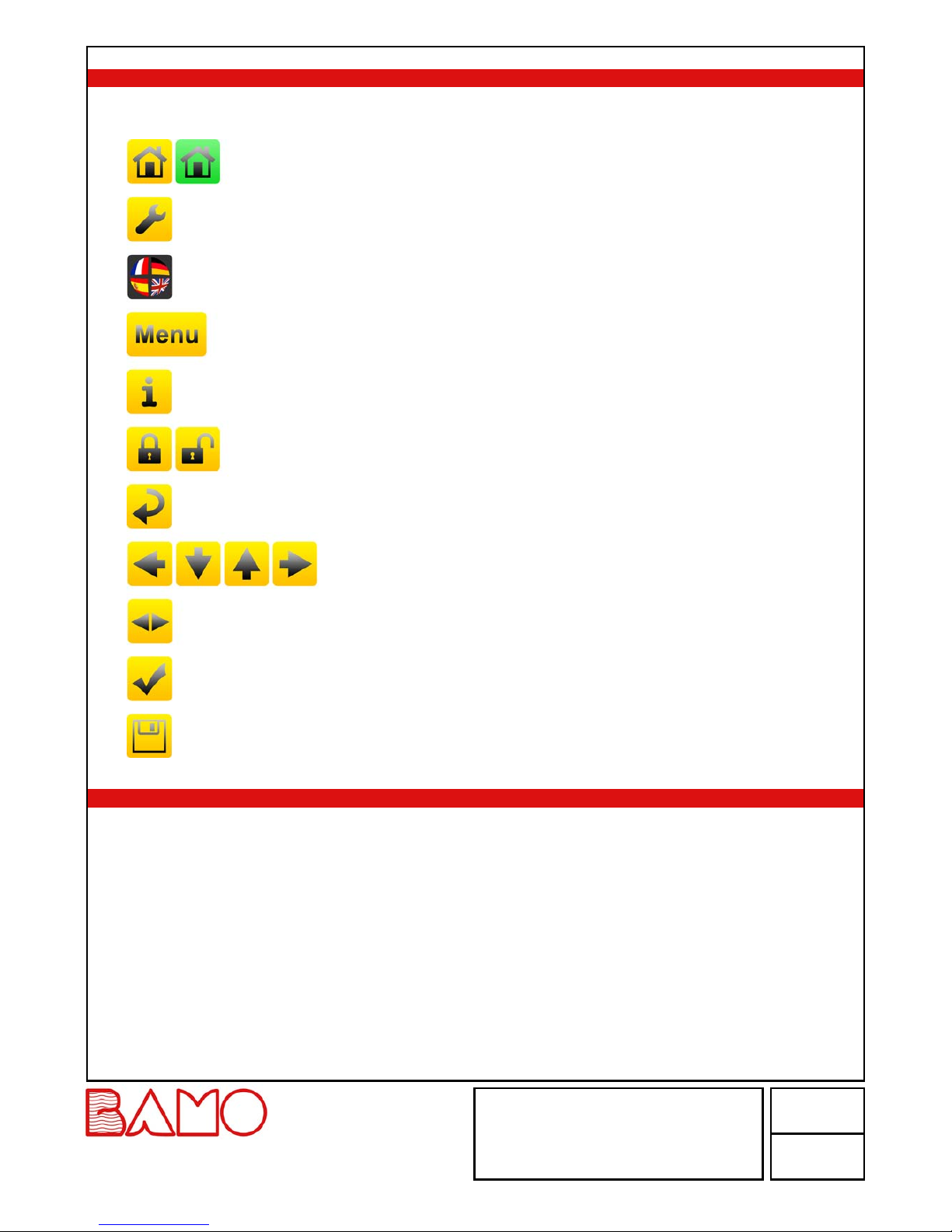
8. CONSULTATION/ MODIFICATION
CONSULTATION mode let the operator to check out all working parameters.
This mode is represented by the closed padlock icon.
To change the settings of the BAMOPHAR, you need to enter in the MODIFICATION mode.
This mode is protected by a password identical to the last 4 digits of the serial number.
On the main display, press MENU icon.
Press the padlock icon and type the 4 last digits of Serial Number.
To validate it, press "OK"; Device is now in MODIFICATION mode (padlock is open).
If the entered keyword is wrong, BAMOPHAR stays in the mode CONSULTATION.
After 30 minutes the mode MODIFICATION switches back to CONSULTATION mode.
Where can we find the serial number?
The serial number (SN) is written on the identification label of the device.
It appears as well in MENU, icon " i " (INFORMATION).
9. pH/ ORP SETTINGS
9.1 ELECTRODE CALIBRATION
For calibration routine, temperature displayed on main menu should be close to the real temperature of buffers.
• To avoid the mixing of buffer solutions, rinse the pH electrode with water each time you change the buffer.
• Never wipe the electrode.
• For a correct calibration, choose the buffer value in relation with the process (e.g. buffer pH 4.00 for a process with acids).
Press MENU and choose ADJUST ELECTRODE.
STANDARD 7.00 pH Plunge the tip of the electrode in the pH 7.00 buffer solution (Ref 9011), then confirm.
Do not forget to remove the electrode protection (translucent cap).
ASYM. +00.00pH Leave the solution for about 5 minutes in order to stabilize the pH 7 measurement, then confirm.
If the measurement for ASYM. (asymmetry) is too high, a message ERROR appears:
- Verify that the buffer in use is the right one.
- Verify all connections and cable.
- In case the trouble persists, change the electrode.
BUFFER 4 pH or 10pH Once the pH measurement with buffer 7.00 is correct, rinse the electrode and plunge the
electrode tip in other buffer solution, or pH 4.00 (Reference 9012) or pH 10 (reference 9013).
Type the pH buffer value, then confirm.
SLOPE 100.0 % Wait a moment for the slope measurement to stabilize, then confirm.
If the slope is weak (<70%), a message “ERROR“ appears.
In such a case, if the buffer is the right one and not obsolete, change the electrode.
DELAY 0000 Sec When the slope is valid (70 to 110%), enter the delay while measurement and outputs stay
blocked at values, previous to calibration routine; then confirm.
SAVE ? To record the calibration parameters, press the icon SAVE.
Do not forget to set up the temperature mode to its previous setting: manual mode (fluid
temperature) or automatic mode (Pt 100 sensor connected), see the menu TEMPERATURE.
MES
23-11-2018 M-107.01-EN-AE 107-01/10
pH/ mV monitors
BAMOPHAR 107
22, Rue de la Voie des Bans · Z.I. de la gare · 95100 ARGENTEUIL
Tel
Fax
+33 (0)1 30 25 83 20
+33 (0)1 34 10 16 05
Web
E-mail
www.bamo.eu
INTERNATIONAL

9.2 SETTING THE RELAY OUTPUTS S1, S2 AND S3 AS THRESHOLDS
9.2.1 COMMENTS ABOUT REGULATION WITH BAMOPHAR
Before to set up or to choose the regulation mode, it is necessary to define the operating mode.
BAMOPHAR 107 allows you to choose between 3 operating modes:
1) ON/ OFF regulation mode with thresholds values S1, S2 and/ or S3
2) Relay regulation mode with proportional bandwidth and dead zones (relays S1 and S2)
3) P.I.D. regulation mode using the 4-20 mA output signal of BAMOPHAR
Specificity of threshold S3:
May be assigned to the external signal (E1): to block the regulation (terminals 5 and 6, see wiring diagram).
In this case, relay S3 becomes a normally closed contact (N.C) and E1 is not active; S3 opens when blocking regulation operates (E1 active).
This means:
- Relay S3 is normally closed (N.C.) if no voltage applies between terminal 5 and 6 (E1 not active).
- Relay S3 will open when voltage applies between terminals 5 and 6 (E1 active)
Consequences of blocking the regulation:
• When working in ON/ OFF regulation mode, there is no additional action on relays S1 and/ or S2.
• However, it is possible for the user to connect the relays S1 and S3 in series to secure the injection (if relay S1 manages the injection of
reagent). When working in relay regulation mode, relays s1 and s2 are opened (non actuated); regulation is inhibited.
• When working in PID regulation mode, the 4-20 mA signal is frozen.
9.2.2 ADJUSTMENT OF THRESHOLDS S1, S2 AND S3 IN MODE ON/OFF REGULATION
Below is a detailed description of the steps to set the threshold S1:
Enter to the menu ADJUST ALARM 1
ALARM 1 ON / OFF To set up output S1, select ON, then confirm.
To disable the relay S1 select OFF mode, then confirm and save the setting.
ALARM 1 MEASURE / TEMP. In ON mode, threshold S1 can be set in MEASUREMENT or TEMPERATURE mode:
MEASURE mode = threshold dedicated to pH or mV (ORP) measurements
TEMP. mode = threshold dedicated to temperature measurement
Select the appropriate mode, then confirm.
ALARM 1 HIGH / LOW HIGH = Trigger when measurement rises over threshold S1
LOW = Trigger when measurement decreases below threshold S1
Select the appropriate actuating mode, then confirm.
ON 08.00 pH / °C Enter the value at which relay S1 will actuate (closing), then confirm.
OFF 07.50 pH / °C Enter the value at which relay S1 will be opened, then confirm.
DELAY UP ON / OFF With or without delay to actuate the relay S1.
TIME 0000 Sec Enter the duration of delay before actuating S1, then confirm.
DELAY DOWN ON / OFF With or without delay to open relay S1
TIME 0000 Sec Enter the duration of delay before opening S1, then confirm.
SAVE ? To record the settings, press the icon SAVE.
All settings for S2 and S3 are available respectively in ADJUST ALARM 2 and ADJUST ALARM 3 menus, identical to S1.
9.2.3 ASSIGNMENT OF S3 THRESHOLD TO EXTERNAL SIGNAL (E1)
Go to the menu ADJUST ALARM 3.
ADJUST ALARM 3 ON / OFF Select the ON mode to set up the output S3, then confirm.
EXTERN. YES / NO If NO : the sequence of settings are same as for S1 or S2 in ON/ OFF regulation mode
If YES = external signal (E1) is assigned to relay S3
Relay S3 becomes a normally closed contact (E1 not active) and will open when blocking of
regulation operates (E1 active).
Confirm the selection.
SAVE ? To record the settings, press the icon SAVE.
MES
23-11-2018 M-107.01-EN-AE 107-01/11
pH/ mV monitors
BAMOPHAR 107
22, Rue de la Voie des Bans · Z.I. de la gare · 95100 ARGENTEUIL
Tel
Fax
+33 (0)1 30 25 83 20
+33 (0)1 34 10 16 05
Web
E-mail
www.bamo.eu
INTERNATIONAL

pH RISING
pH DECREASING
Trigger point RELAY ON
Trigger point RELAY OFF
Time
pH pH
Time
8.5
7
Relay actuated
Relay actuated
Delay before relay switches ON
Actuation of S2
pH pH
Trigger point RELAY OFF
Trigger point RELAY ON
Time
Time
Relay ON
Relay ON
Delay before relay switches OFF
8.5
7
9.3 SETTING OF TEMPERATURE
Go to the menu TEMPERATURE
MEASURE: AUTO / MANUAL AUTO : With signal from a sensor Pt 100 Ohm at 0°C
MANUAL : Without sensor Pt 100 Ω; temperature value is entered manually.
Confirm the selection.
FLUID T. + 025.0°C If the MANUAL mode is selected, enter the temperature value of the fluid, in °C, then confirm.
SAVE ? To record the settings, press the icon SAVE.
9.4 SETTINGS OF ANALOGUE OUTPUT FOR MEASUREMENT
Go to menu OUTPUT mA pH (or RH for ORP)
HIGHER 14.00 pH Enter the highest value for pH (or ORP) for the output signal at 20.00 mA, then confirm.
LOWER 00.00 pH Enter the lowest value for pH (or ORP) for the output signal at 4.00 mA (or 0.00 mA), then confirm.
OUTPUT 4/20 mA or 0/20 mA Select the right scale 4...20 mA or 0...20 mA for output signal, then confirm.
SAVE ? To record the settings, press the icon SAVE.
9.5 SETTINGS OF ANALOGUE OUTPUT FOR TEMPERATURE
Go to menu OUTPUT mA TEMP.
HIGHER +160.0°C Enter the temperature value in °C for output signal value at 20.00 mA, then confirm.
LOWER +000.0°C Enter the temperature value in °C for output signal value output signal at 4.00 mA (or 0.00 mA),
then confirm.
OUTPUT 0/20 mA or 4/20 mA Select the right scale 4...20 mA or 0...20 mA for output signal, then confirm.
SAVE ? To record the settings, press the icon SAVE
9.6 FORCED RELAY
This menu allows to test manually the relays S1, S2, S3 and S4 through simulations.
Status of last one (S4) is OFF (non actuated) by default. Test begins with threshold S1 with status relay OFF.
To test it, press the arrows SELECTION to switch relay to ON status (activated).
Confirm to go to next threshold; Same routine for testing S2, S3 and S4.
MES
23-11-2018 M-107.01-EN-AE 107-01/12
pH/ mV monitors
BAMOPHAR 107
22, Rue de la Voie des Bans · Z.I. de la gare · 95100 ARGENTEUIL
Tel
Fax
+33 (0)1 30 25 83 20
+33 (0)1 34 10 16 05
Web
E-mail
www.bamo.eu
INTERNATIONAL

9.7 SETTING OF THE RELAY REGULATION MODE
Go to the menu RELAY REGULATION
• There is no access to settings of relay regulation mode if relays S1 and/ or S2 are operating; So, go to::
ON / OFF MODE To access to this mode, first go back to menus ADJUST ALARM S1 and S2 to set them in OFF
mode.
• There is no access to relay regulation mode when PID regulation is operating; So go to:
PID MODE To access to relay regulation mode, go to to the menu REGUL. PID to switch it OFF.
• Regulation mode is thus accessible if, and only if, the THRESHOLD and PID modes are deactivated.
REGULATION ON / OFF Select ON mode to set up parameters, then confirm.
SET VAL 07.00 pH Enter the threshold value, then confirm.
T. CYCLE 0060 Sec Enter the cycle time according to the process, then confirm.
HIGH PB 00.80 pH Enter the differential for upper bandwidth, then confirm.
Note: Output S2 is dedicated for upper bandwidth.
LOW PB 00.50 pH Enter the differential for lower bandwidth, then confirm.
Note: Output S1 is dedicated to lower bandwidth.
HIGH DZ 00.50 pH Enter the differential value for the upper dead zone, then confirm.
LOW DZ 00.20 pH Enter the differential value for the lower dead zone, then confirm.
SAVE ? To record the settings, press the icon SAVE.
Cycle time
High limit
Set point
Low limit
Time
S1 actuated
No action
Dead zone
Measurement S2
EXAMPLE:
For settings such as following:
- Set point: pH 7.00
- Cycle time: 10 s
- Upper bandwidth: 3 pH (i.e. high limit is pH 10.00)
- Lower bandwidth: 1 pH (i.e. lower limit is pH 6.00)
- High dead zone: 0.3 pH (from pH 7.00 to 7.30)
- Lower dead zone: 0.7 pH (from pH 6.30 to 7.00)
Results for operating regulation:
- Above the High limit, between pH 10 and 14, output S2 is continuously activated (continuous injection of base, pH will decrease).
- Below the Low limit, between pH 0 and 6, output S1 is continuously activated (continuous injection of acid, pH will increase).
- Within the Dead zones, between pH 6.3 and 7.3, the outputs S1 and S2 are not actuated.
- When measurement is above Dead zone and below High limit (pH 7.3 to 10), or below Dead zone and above the Low limit (pH 6 to 6.3), the
outputs S1 or S2, are actuated during a time proportional to the difference between set point and measurement.
Actuation time = Cycle time x (Measurement - Set point) / High or Low bandwidth
Caution:
According to the above example, if measurement is pH 7.80, actuation time = 3 s: 2.66 = 10 x (7.8 - 7) / 3
MES
23-11-2018 M-107.01-EN-AE 107-01/13
pH/ mV monitors
BAMOPHAR 107
22, Rue de la Voie des Bans · Z.I. de la gare · 95100 ARGENTEUIL
Tel
Fax
+33 (0)1 30 25 83 20
+33 (0)1 34 10 16 05
Web
E-mail
www.bamo.eu
INTERNATIONAL

9.8 OUTPUT S4 SETTINGS
9.8.1 DEFAULT SETTING
By default, relay S4 is dedicated to alarms on pH and temperature faults:
- The contact closes, if the measurement is less than pH 0.10
- The contact closes if the measurement is above pH 14.10.
- The contact closes if the sensor Pt 100 is faulty (damaged cable).
Otherwise, relay S4 can be dedicated to another function:
• Either in alarm (relay fault S1 or S2): See § ADJUST ALARM
• Or cleaning function: See § CLEANING PROBE
9.8.2 ADJUST ALARM
This function activates relay S4 when the switch-on time of relays S1 or S2 is too long (e.g. injection time too long).
Go to the menu ADJUST ALARM
• This ALARM function is not available if the CLEANING PROBE mode is activated; So, go to:
CLEANING PROBE MODE Deactivate first the cleaning function in CLEANING PROBE menu before to access to ADJUST
ALARM menu..
• If the CLEANING PROBE mode is disabled, the ADJUST ALARM function is available:
WITH ALARM / WITHOUT ALARM Select WITH ALARM to activate the relay S4, then confirm.
TIME S1 0005 Sec Enter the holding time max. for relay S1, then confirm.
TIME S2 0020 Sec Enter the holding time max. for relay S2, then confirm.
SAVE ? To record the settings, press the icon SAVE.
9.8.3 CLEANING PROBE
This function actuates the S4 relay when automatic cleaning of the electrode is required.
In order not to disturb the regulation, measurements are frozen during the cleaning routine.
Go to the menu CLEANING PROBE.
• If alarms are set up in ADJUST ALARM, the cleaning mode menu is not available; So, go to:
ADJUST ALARM To access to the CLEANING PROBE menu, switch alarms mode to WITHOUT ALARM in menu
ADJUST ALARM.
• If the ALARM mode is not activated, the CLEANING PROBE function is available.
CLEANING YES / NO Select YES to set up the cleaning routine, then confirm.
PERIOD 2300 Sec Enter the cycle time between two cleaning routines, then confirm.
TIME 0010 Sec Enter the duration of cleaning routine, then confirm.
DELAY 0010 Sec Enter the delay before the measurement is resumed.
SAVE ? To record the settings, press the icon SAVE.
9.9 PID REGULATION
REGUL. PID allows seting of a PID regulation through analogue output (0...20 or 4...20 mA) between terminals 3 and 4.
This output is no more dedicated to the copy of temperature measurement.
Go to the menu REGUL. PID
REGULATION ON / OFF Select ON to set up the function PID REGULATION, then confirm.
REGUL. AUTO / MANU Select AUTO to access to parameters, then confirm.
SET VAL 07.00 pH Enter the value of desired trigger point, then confirm.
GAIN : 4.800 Enter the required proportional gain value, then confirm.
Ti : 0050 Sec Enter the value for integral timer, then confirm.
Td : 0012 Sec Enter the required value for derivative timer, then confirm.
ACID INJECTION / BASE INJECTION Select the right chemical, then confirm.
OUTPUT 4/20 mA or 0/20 mA Select the required output signal range, then confirm.
SAVE ? To record the settings, press the icon SAVE.
Note: To block the PID regulation, set a voltage of 24V DC (=20 mA)between terminals 5 (+) and 6 (0).
MES
23-11-2018 M-107.01-EN-AE 107-01/14
pH/ mV monitors
BAMOPHAR 107
22, Rue de la Voie des Bans · Z.I. de la gare · 95100 ARGENTEUIL
Tel
Fax
+33 (0)1 30 25 83 20
+33 (0)1 34 10 16 05
Web
E-mail
www.bamo.eu
INTERNATIONAL

METHOD FOR ADJUSTMENT OF PID PARAMETERS
In order to setup values for start-up on PID, we recommend to use the Ziegler-Nichols open loop method.
Proceed as follows:
- Connect a recorder to the analogue output or write the displayed values, then draw the diagram pH vs. time.
- Switch on MANUAL the PID regulation mode.
- Reach and keep the measurement close to the set point by adjusting the PID output.
- Apply a step (∆Cde) of 10 % for instance, on the analogue output (e.g. If preset value was 30%, apply 40%).
- Note on the diagram the corresponding time for this event (step of +10%).
- Find out on this diagram both times t and T:
t = delay of response
T = Time corresponding to a variation Δm of measurement equal to percentage of variation
∆Cde of output (∆m = ∆Cde)
This value may be found out from the slope at the beginning of measurements.
- Set up the PID parameters with the values from the following table:
Regulation Gain Ti [s] Td [s]
PID 1,2 x T/t 2 x t 0,5 x t
PI 0,9 x T/t 3,3 x t 00
P T/t 9999 00
PID
analogue
output
8.4
In MANUAL mode (REGUL. MANU)
pH measurement
Reached set point
Time
Time
∆Cde = 10 %∆m = 10 %
To
To
9.10 TYPE OF INSTRUMENT
pH / RH CHOICE Choose your application, then confirm
pH - METER for pH monitoring
RH - METER for ORP applications
SAVE ? To record the settings, press the icon SAVE.
9.11 FORCED MEASURE
It is possible to force the measurement or the PID.
The first line shows the current measurement.
Confirm to access to the keyboard.
Enter the value you need to simulate.
Note: The value is immediately considered by BAMOPHAR (thresholds, regulation, 4-20mA outputs ...)
To exit this menu, press icon RETURN KEY.
Note : It is possible to force the output 4-20 mA for PID when PID regulation is in manual mode (REGUL. MANU).
If PID regulation is operating, the display of analogue output is in %.
MES
23-11-2018 M-107.01-EN-AE 107-01/15
pH/ mV monitors
BAMOPHAR 107
22, Rue de la Voie des Bans · Z.I. de la gare · 95100 ARGENTEUIL
Tel
Fax
+33 (0)1 30 25 83 20
+33 (0)1 34 10 16 05
Web
E-mail
www.bamo.eu
INTERNATIONAL
Table of contents
Other Bamo Measuring Instrument manuals

Bamo
Bamo BAMOWIZ OX 452 User manual

Bamo
Bamo MEMPRO Ex C User manual

Bamo
Bamo Pooltest 3 User manual

Bamo
Bamo MAXIMAT CX User manual

Bamo
Bamo MW-10 User manual

Bamo
Bamo MAXIMAT LW CN-SDR User manual

Bamo
Bamo FS4 User manual

Bamo
Bamo IER Turbicube 20 User manual

Bamo
Bamo TURBISENS User manual

Bamo
Bamo BAMOPHAR 759 User manual
Popular Measuring Instrument manuals by other brands

Interscan Corporation
Interscan Corporation GF1900 manual

BEA
BEA LZR-MICROSCAN U920 user guide

Hanna Instruments
Hanna Instruments HI 9219 instruction manual

Futech
Futech MULTICROSS 5 SUPER Vision user manual

Davis Instruments
Davis Instruments Rain Collector instruction manual

Norsonic
Norsonic nor121 instruction manual