Page 2
443 M1 01 E 10-03-2015
FUNCTI NS – DESCRIPTI N
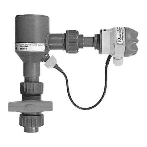
- TURBISENS determines the turbidity of liquids according ISO 7027, using infrared light in pulsating light mode with 2 emitters and
1 receiver.
- Output signal: 4 to 20 mA
- Automatic compensation is assured on external light and colour.
M UNTING : Caution! The probe must be installed vertically using the supplied bracket in order to let a free space of 10 cm
as a minimum from the tank or channel floor. The cable sensor is connected with an IP67 protected connector to the head housing.
RANGE SET UP
●Connect the power supply, at this moment the initializing
sequence runs until the green ED blinks.
●Press the push button. Display: "OUT"
●Press the push button once more. Display: "present value"
●Choose the right range with the selector.
●The instrument after 5 seconds saves your selected range
and returns back to measuring mode.
See fig.1: Configuration menu
Switching the power on:
The initializing sequence begins, display indicates the sofware
version.
Whitin 3 seconds, green ED blinks: measuring mode is opera-
ting and display indicates the measured turbidity.
Compensation:
Colour compensation only for 0...50 and 0...100 FNU ranges.
Status indicators:
Blinking green ED: = All in operation, measurement mode
OFF green ED: = Faulty power supply
ON red ED: = Dysfunction on 4-20 mA output
Error indications on the display:
"SUN" –> Too much external light
"dlrt" –> Dirty glass windows
" " –> Over range
"noSd" –> Faulty probe or not connected,
broken cable
Dysfunction diagnostics
- No entry on colour compensation:
This function is available only for two ranges 0...50 and
0...100 FNU.
Choose an appropriate range to check this function.
- No choice of range over 100 FNU:
The colour compensation is working and does not allow any
range over 0...100 FNU.
Set off the colour compensation and set up the right range.
Monitor
+-+
www.ier.de
Enter
- +
-
4-20mA 10-30V
Power
Output
DC
LED status
Display
parameters
and turbidity
Rotating selector for
parameters selection
and
Push button for
parameters entry
Galvanic
insulated
output Input
Power supply
Fig.1
SAFETY PRECAUTI NS
• nly qualified person should operate, install and assure the maintenance. All International and European recommendations on electrical
installation should be applied.
• The device may only be connected to supply power, which complies with the specifications included in the technical data.
• The device must be disconnected from all sources of power during installation and maintenance work.
• The device may only be operated under the conditions specified in the operating instructions.
