Banner Engineering Corp. • Minneapolis, U.S.A.
www.bannerengineering.com • Tel: 763.544.3164
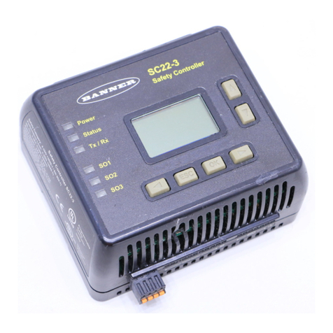
SC22-3 Safety Controller
Instruction Manual
Table of Contents
Important . . .
read this before proceeding!
It is the responsibility of the machine designer, controls engineer,
machine builder and/or maintenance electrician to apply and maintain
this product in full compliance with all applicable regulations and
standards. The product can provide the required safeguarding
function only if it is properly installed, properly operated, and properly
maintained. This manual attempts to provide complete installation,
operational, and maintenance instruction. Reading the manual
completely is highly recommended. Please direct any questions
regarding the application or use of the product to the Banner
Engineering Applications department at the phone number or address
shown on the back cover.
For more information regarding U.S. and international institutions
that provide safeguarding application and safeguarding product
performance standards, see the list on the inside of the back cover.
Use of Warnings
Warnings are intended to remind the machine designer, control
engineer, machine builder, maintenance electrician, or end user
how to avoid misapplication of this product and effectively apply
the Safety Controller to meet the various safeguarding application
requirements. Reading and abiding by the warnings is highly
recommended.
WARNING . . .
It is the responsibility of the qualified person who
configures, installs, or maintains the SC22-3 Safety
Controller to:
• Carefully read, understand and follow the information in this
manual.
• Perform a risk assessment of the specific machine guarding
application.
• Determine what safeguarding devices and methods are
appropriate per the requirements defined in ISO 13849-1 and
EN 945-1 and that are referenced in the SC22-3 manual.
• Create and confirm each SC22-3 configuration and then verify that
the entire safeguarding system (including input devices and output
devices) is operational and working as intended.
• Periodically re-verify as needed, that the entire safeguarding
system is working as intended.
Failure to follow any of these recommendations can potentially
create a dangerous condition that may lead to serious injury
or death.
Section1. Overview.............................................1
1.1 Applications................................................1
1.2 DesignandTesting .........................................1
1.3 Components...............................................2
1.4 Configuring the Safety Controller . . . . . . . . . . . . . . . . . . . . . . . . . . . . . . .4
1.5 InputandOutputDevices ....................................7
1.6 SystemSettings ...........................................10
1.7 InternalLogic..............................................11
1.8 PasswordOverview ........................................11
1.9 ConfirmingaConfiguration...................................11
Section 2. Components and Specifications . . . . . . . . . . . . . . . . . . . . . . .12
2.1 Models...................................................12
2.2 Specifications .............................................14
2.3 Dimensions . . . . . . . . . . . . . . . . . . . . . . . . . . . . . . . . . . . . . . . . . . . . . . .15
Section3. SystemInstallation...................................16
3.1 AppropriateApplication .....................................16
3.2 SafetyInputDevices........................................17
3.3 Non-SafetyInputDevices....................................20
3.4 Resets...................................................21
3.5 SafetyInputFunctions ......................................22
3.6 EDM, OSSD (Safety Output), and FSD Hookup . . . . . . . . . . . . . . . . . .25
3.7 StatusOutputs ............................................33
3.8 CommissioningCheckout....................................33
Section 4. Configuration — PC Interface (PCI). . . . . . . . . . . . . . . . . . . . . 34
4.1 PC Interface (PCI) Overview. . . . . . . . . . . . . . . . . . . . . . . . . . . . . . . . . .34
4.2 ConfigurationTools.........................................35
4.3 BuildingaConfiguration.....................................36
4.4 Revise an Existing Configuration . . . . . . . . . . . . . . . . . . . . . . . . . . . . . .41
4.5 Other Functions . . . . . . . . . . . . . . . . . . . . . . . . . . . . . . . . . . . . . . . . . . .41
Section 5. Configuration — Onboard Interface (OBI) . . . . . . . . . . . . . . .43
5.1 Onboard Interface (OBI) Overview . . . . . . . . . . . . . . . . . . . . . . . . . . . .43
5.2 RunMode................................................45
5.3 ConfigurationMode.........................................46
5.4 EditConfiguration..........................................49
5.5 AddanInput..............................................52
Section 6. Operation Instructions. . . . . . . . . . . . . . . . . . . . . . . . . . . . . . . .55
6.1 Display Controller Information — PC Interface (PCI) . . . . . . . . . . . . . . .55
6.2 Display Controller Information — Onboard Interface (OBI) . . . . . . . . . .55
6.3 ManualReset.............................................59
6.4 System Resets and Lockout Conditions . . . . . . . . . . . . . . . . . . . . . . . . .59
6.5 Reset Signal Requirements . . . . . . . . . . . . . . . . . . . . . . . . . . . . . . . . . .59
Section7. SystemCheckout....................................60
7.1 ScheduleofCheckouts .....................................60
7.2 Commissioning Checkout Procedure . . . . . . . . . . . . . . . . . . . . . . . . . . .61
7.3 Initial Setup and Commissioning/Periodic Checkouts . . . . . . . . . . . . . .62
Section 8. Troubleshooting and Maintenance . . . . . . . . . . . . . . . . . . . . .67
8.1 Cleaning .................................................67
8.2 Repairs and Warranty Service . . . . . . . . . . . . . . . . . . . . . . . . . . . . . . . .67
8.3 Troubleshooting — Finding and Fixing Faults . . . . . . . . . . . . . . . . . . . .67
8.4 RecoveringfromaLockout...................................70
8.5 FaultDiagnostics—PCI.....................................70
8.6 FaultDiagnostics—OBI.....................................71
Appendix A. Input Device and Safety Category Reference . . . . . . . . . . 73
A.1 Safety Circuit Integrity and
ISO13849-1 (EN954-1) Safety Circuit Principles . . . . . . . . . . . . . . . . . .73
A.2 Protective(Safety)Stop .....................................75
A.3 InterlockedGuardorGate ...................................76
A.4 OpticalSensor.............................................80
A.5 Two-HandControl..........................................82
A.6 SafetyMats ..............................................84
A.7 Emergency Stop Push Buttons. . . . . . . . . . . . . . . . . . . . . . . . . . . . . . . .87
A.8 Rope/CablePull ...........................................89
A.9 EnablingDevice ...........................................91
A.10 Bypass Switches (Bypassing Safeguards) . . . . . . . . . . . . . . . . . . . . . .93
A.11 MuteSensorPair ..........................................95
Appendix B. Configuration Tutorial — PC Interface (PCI) . . . . . . . . . .101
Appendix C. Configuration Tutorial — Onboard Interface (OBI). . . . .113
Glossary ................................................122


