baridi DH49 User manual

Baridi 5L Universal Beer Dispenser Tap
with Integrated Cooling
Model No. DH49
Thank you for purchasing a Baridi product from the Dellonda range. Manufactured to a high standard,
this product will, if used according to these instructions, and properly maintained, give you years of
trouble free performance.
DH49 v1 Issue 1 25/08/20
2
Important Information
Please read these instructions carefully and note any safe operational requirements, warnings &
cautions. Use the product correctly and with care for the purpose for which it is intended. Failure
to do so may cause damage and/or personal injury and will invalidate the warranty. Keep these
instructions safe for future use.
• ELECTRICAL SAFETY
• WARNING! It is the user’s responsibility to
check the following:
• Check all electrical equipment and appliances
to ensure that they are safe before using.
Inspect power supply leads, plugs and all
electrical connections for wear and damage.
Dellonda recommend that an RCD (Residual
Current Device) is used with all electrical
equipment.
You may obtain an RCD by contacting your
local domestic stockist. If the product is used
in the course of business duties, it must be
maintained in a safe condition and routinely
PAT (Portable Appliance Test) tested.
• Electrical safety information: It is important
that the following information is read and
understood.
• Ensure that the insulation on all cables and on
the appliance is safe before connecting it
to the power supply.
• Regularly inspect power supply cables and
plugs for wear or damage and check all
connections to ensure that they are secure.
• Important: Ensure that the voltage rating on
the appliance suits the power supply to be
used and that the plug is tted with the correct
fuse - see fuse rating in these instructions.
• DO NOT pull or carry the appliance by the
power cable.
• DO NOT pull the plug from the socket by the
cable.
• DO NOT use worn or damaged cables, plugs or
connectors.
• Ensure that any faulty item is repaired or
replaced immediately by a qualied electrician.
• This product is tted with a BS1363/A 13 Amp
3 pin plug. If the cable or plug is damaged
during use, switch off the electricity supply and
remove from use. Ensure that repairs are
carried out by a qualied electrician.
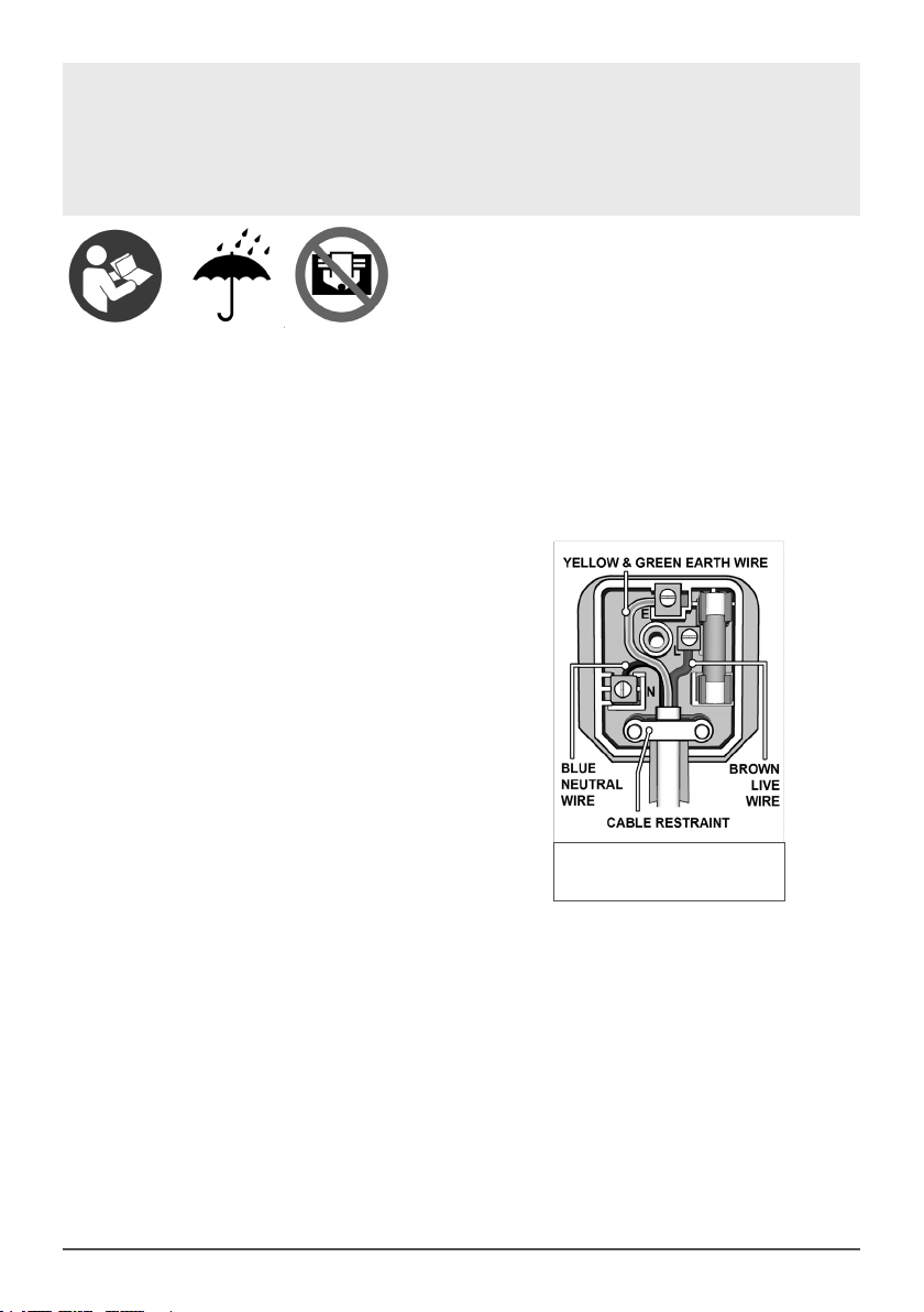
• Replace a damaged plug with a BS1363/A 13
amp 3 pin plug. If in doubt contact a qualied
electrician.
A) Connect the GREEN/YELLOW
earth wire to the earth terminal ‘E’.
B) Connect the BROWN live wire to the
live terminal ‘L’.
C) Connect the BLUE neutral wire to
the neutral terminal ‘N’.
• Ensure that the cable outer sheath extends
inside the cable restraint and that the restraint
is tight.
• Dellonda recommend that repairs are carried
out by a qualied electrician.
• GENERAL SAFETY
• DO NOT remove keg until fully empty.
Replacement fuse rating:
13A
Refer to
instructions
Keep out of
rain
Do not cover

3
• DO NOT remove CO2 cartridge until fully empty.
• DO NOT cover the unit while working.
• DO NOT place in direct sunlight.
• WARNING: Ensure the supply cord is not
trapped or damaged.
• WARNING: This appliance is intended
• This appliance can be used by children
aged from 8 years and above and persons
with reduced physical, sensory or mental
capabilities or lack of knowledge and
experience if they have been given supervision
or instruction concerning the use of the
appliance in a safe way and understand the
hazards involved. Children shall not play with
the appliance. Cleaning and user maintenance
shall not be made by children without
supervision.
• INTRODUCTION
• Universal tting for all 5L beer kegs.
Thermoelectric cooling technology chills beer
to as low as 4°C. Keeps beer fresh for up to 30
days. Removable drip tray with raised lip helps
prevent spillage. LED temperature gauge.
Operates using standard 16g CO2canisters.
Modern stainless steel and black design.
• SPECIFICATION
• Model no: DH49
• Lowest temperature: 4°C
• Rated current: 0.76A
• Voltage: 220-240V
• Frequency: 50Hz
• Noise level: ≤38dB(A); Ambient noise ≤25dB(A)
• Dimensions (W x D x H): 335 x 460 x 470mm
• Keg capacity: 5L
• INSTALLATION
• DO NOT locate the unit in a damp or moist
location.
• Operate unit on dry and level surface.
• NOTE: The unit is designed to be free-standing
and to ensure adequate ventilation, leave at
least 12 cm free space around the unit.
• Once in position allow the unit to rest for an
hour before turning it on.
• OPERATION
• Read this document thoroughly and assemble
the unit accordingly.
• Check that the unit is fully assembled and
installed in the appropriate location.
• Ensure that CO2valve is fully closed.
• Locate drip tray (g.1) into body and make
sure that the drain switch (g.1) is set in the
off (upright) position.
• Carefully pour 800 ml of clean tap water into
the cooling cavity.
• DO NOT exceed the ‘MAX’ mark inside the
chamber when lling.
• Select a temperature setting using the LED
interface on the top of the unit (g.1).
• NOTE: The LED display shows the current
temperature of the beer and pressing
and holding the ‘+’ key displays the set
temperature.
• Allow the unit time to reach the set
temperature before placing keg into the
cooling compartment.
• If using a ‘universal’ beer keg, open the
pressure control valve (g.1) and gently pull
the tap handle to begin ow.
• Use the pressure control valve to control the
beer’s ow rate and level of frothing.
• If serving Heineken beer, ensure the pressure
control valve is fully closed as the kegs have
their own internal pressurising device hence
there is no need to use the gas.
Pressure
Control
Drain
LED
Display
Drip tray
Latch
Fig.1

4
• CO2CARTRIDGE
• DO NOT attempt to remove a cartridge if it is
not empty.
• NOTE: Ensure that the pressure control
valve is set to fully closed before attempting
removal or replacement of a gas cylinder.
• NOTE: The cartridge mount has an ‘O’ ring
seal. If the seal is proven to be leaking,
replacement ‘O’ rings are supplied in the kit.
• NOTE: The cartridge used on this unit is NOT
the threaded type.
• Open the unit lid by pressing the button on the
lid (g.1).
• Unscrew the CO2 bottle housing from its
location within the lid and remove empty
cartridge from the unit (g.2).
• Check that the ‘O’ ring seal is in situ and in
good condition. Replace seal if in doubt.
• Place new cylinder into housing and relocate
into head.
• CARTRIDGE PIERCING CARE
• The cartridges used in this unit are of the blind
type i.e. they are NOT threaded. As such they
require piercing in order to operate.
• Should the piercing tool need replacement,
remove the empty gas cartridge.
• Carefully remove the ‘O’ ring seal from the
cartridge nest and lift out the installed piercing
tool (g.3).
• Insert the replacement piercing tool and ‘O’
ring noting that the orientation of the piercing
point is towards an inserted gas cartridge.
• BEER DISPENSING UNIT
• Assemble the dispensing unit by locating the
peg on the main body into the notch in the
clamp frame (g.4) NOTE: It can only t in one
direction.
• Screw the delivery tube onto the dispensing
unit making sure that the ‘O’ ring seal is in situ
and in good condition. Replace seal if in doubt.
• CONNECT DISPENSER TO TAP
• Assemble clear hose and connector as g.5.
• Lift the lid of the unit and press the release
mechanism on the tap body to release the
centre section of the tap body (g.5).
• Place the clear hose through the hole in the
removable centre section and while pushing
the tap handle down in the open position,
thread the clear hose down into the tap body.
CO2Cartridge housing
Pierce tool and ‘O’ ring
Fig.2
Fig.3
Fig.4

5
• NOTE: Ensure a rm leak proof location within
the tap body. Relocate centre section back to
original position.
• MOUNTING A UNIVERSAL KEG
• NOTE: Allow beer to fully settle before
attempting to t dispensing unit.
• NOTE: DO NOT leave keg standing in direct
sunlight or near a heat source.
• NOTE: It is recommended that you allow the
keg to cool for some time before use.
• NOTE: Carefully read any information
provided by the beer manufacturer that
relates to the keg and its operation.
• If tted, remove keg safety clasp according to
keg manufacturers instructions.
• Pierce keg seal with beer dispensing unit
probe (g.6).
• Push the tube down as far as it will go in
order to be able to t dispenser unit onto keg
rim.
• If the keg seal is of the type that is fully
removable, use the supplied tapered seal
(g.11) to make a leak proof seal.
• NOTE: The dispensing unit has a directional
arrow that indicates the direction of CO2 ow
through it.
• Ensuring directional ow as described above,
x dispensing unit into keg rim using the rim
of the keg to provide grip (g.7).
• Clip left side to keg rim and close opposite
side of clip under keg rim.
• Connect CO2 feed pipe and beer delivery tube
to either side of the unit by depressing white
tabs to allow full and leak proof engagement.
• MOUNTING A HEINEKEN KEG
• NOTE: Heineken kegs are pre-charged
with CO2 and DO NOT need the use of the
regulator.
• NOTE: Before connecting the keg ensure that
the tap is in the fully closed position.
• Remove the plastic cap from the keg using a
at head screwdriver.
• Using the Heineken adaptor (g.9) and before
tting it to the keg, attach the clear beer tube
to the Heineken adaptor and the other end to
the tap unit (g.8).
• Mount the adaptor into the keg by pressing it
into keg hole and clipping it in place.
• Carefully close the top cover.
• To remove the adaptor squeeze side tabs to
avoid damaging the adaptor (g.9).
Release
Button
Connection direct
To dispensing unit
Pierce keg seal
And push down
Clip unit under keg rim
Fig.5
Fig.7
Fig.6
Centre
section
Other baridi Kitchen Appliance manuals


