Bartell TS100 User manual

BARTELL MORRISON INC. BARTELL MORRISON (USA) LLC
375 ANNAGEM BLVD, MISSISSAUGA, ONTARIO, CANADA, L5T 3A7, 905-364-4200 FAX 905-364-4201
200 COMMERCE DRIVE, FREEHOLD, NEW JERSEY, USA, 07728, 732-566-5400 FAX 732-5444
Doc. # OI – B09006
Orig. Rel. – 06/2005
Curr. Rev. – 03
Rev. Date – 06/2014
INSTRUCTION MANUAL & PARTS BOOK
TS100 RIDE-ON TROWEL
POWERFUL - EFFICIENT - DEPENDABLE

TS100 RIDE-ON TROWEL INSTRUCTION MANUAL
BARTELL MORRISON INC. BARTELL MORRISON (USA) LLC
375 ANNAGEM BLVD, MISSISSAUGA, ONTARIO, CANADA, L5T 3A7, 905-364-4200 FAX 905-364-4201
200 COMMERCE DRIVE, FREEHOLD, NEW JERSEY, USA, 07728, 732-566-5400 FAX 732-566-5444
Created: 06/05
Revised: 06/14
- 2 -
SAFETY PRECAUTIONS
DANGER
EXPLOSION HAZARD
Never operate the machine in an
explosive atmosphere, near
combustible materials or where
ventilation does not clear exhaust
fumes.
WARNING
BURN HAZARD
Never come into contact with the
engine or muffler when engine is
operating or shortly after it is
turned off. Serious burns may
occur.
WARNING
ROTATING HAZARD
Never place hands or feet inside
safety guard rings. Serious injury
will result from contact with rotating
blades.
CAUTION
MOVING PARTS
Before starting the machine ensure
that all guards and safety devices
are in place and functioning
properly.
ATTENTION
READ OWNERS MANUAL
Read and understand operator's
manual before using this machine.
Failure to follow operating
instructions could result in serious
injury or death.
!
!
!
!
!

TS100 RIDE-ON TROWEL INSTRUCTION MANUAL
BARTELL MORRISON INC. BARTELL MORRISON (USA) LLC
375 ANNAGEM BLVD, MISSISSAUGA, ONTARIO, CANADA, L5T 3A7, 905-364-4200 FAX 905-364-4201
200 COMMERCE DRIVE, FREEHOLD, NEW JERSEY, USA, 07728, 732-566-5400 FAX 732-566-5444
Created: 06/05
Revised: 06/14
- 3 -
TABLE OF CONTENTS
QUALITY ASSURANCE/MACHINE BREAK-IN................................ 4
RIDE-ON POWER TROWEL WARRANTY........................................ 5
MAINTENANCE RECORD................................................................. 6
ROUTINE SERVICE INTERVALS...................................................... 7
FOREWORD....................................................................................... 9
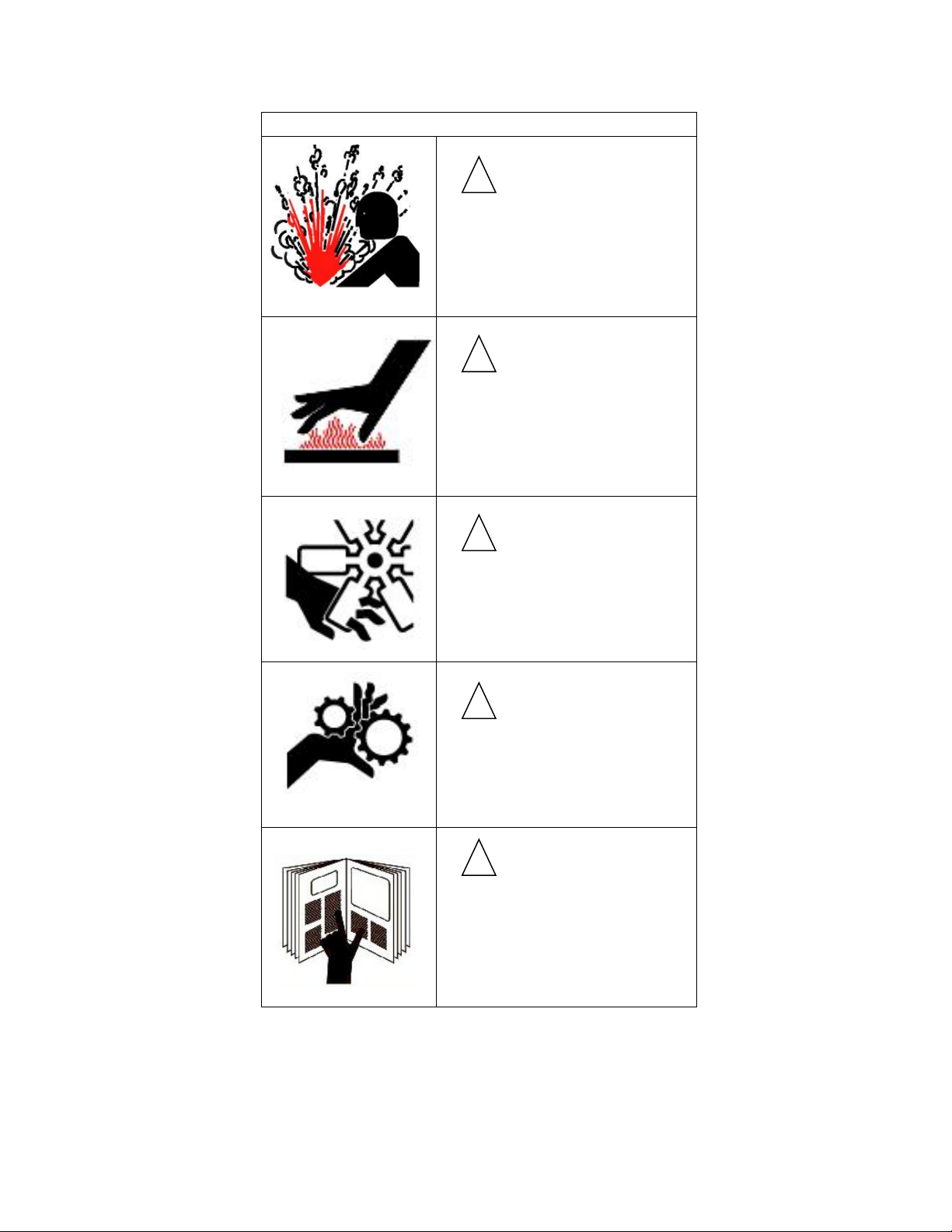
SAFETY PRECAUTIONS................................................................... 9
ASSEMBLY INSTRUCTIONS............................................................ 9
1. BATTERY........................................................................................ 9
2. PITCH CONTROL SYSTEM (FIGURE 1)....................................... 9
3. SEAT ASSEMBLY ........................................................................ 10
4. TRANSPORTER ASSEMBLY....................................................... 10
OPERATING INSTRUCTIONS......................................................... 10
1. STARTING PROCEDURES - WARM TEMPERATURES ............ 10
2. STARTING PROCEDURES - COLD TEMPERATURES.............. 10
3. STOPPING PROCEDURES.........................................................10
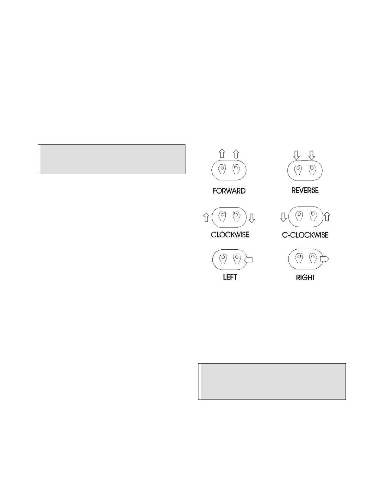
4. STEERING (FIGURE 2)................................................................ 10
5. FLOAT/TROWEL PITCH SETTING.............................................. 11
6. BLADE SYNCHRONIZATION (FIGURE 3)................................... 11
7. TRANSPORTER USE................................................................... 11
MAINTENANCE INSTRUCTIONS.................................................... 11
1. GENERAL..................................................................................... 11
2. AIR CLEANER.............................................................................. 11
3. SPARK PLUG............................................................................... 11
4. BELT CHANGE PROCEDURE..................................................... 12
5. BELT TENSIONING SPECIFICATION (FIGURE 4)..................... 12
LUBRICATION ................................................................................. 12
1. ENGINE OIL.................................................................................. 12
2. SPIDER PLATE ............................................................................ 12
3. GEARBOX ....................................................................................12
4. GEARBOX OIL CHANGE.............................................................12
5. GREASE FITTINGS...................................................................... 12
ASSEMBLY DRAWINGS AND PARTS LIST...................................13
1. CHASSIS ASSEMBLY (FIGURE 1) ..............................................14
CHASSIS PARTS LIST.................................................................16
2. POWERPLANT ASSEMBLY (FIGURE 2).....................................18
POWERPANT PARTS LIST..........................................................19
3. DRIVE TRAIN ASSEMBLY (FIGURE 3) .......................................20
DRIVE TRAIN PARTS LIST..........................................................21
4. STEERING ASSEMBLY (FIGURE 4)............................................22
STEERING PARTS LIST...............................................................23
5. GEARBOX ASSEMBLY (FIGURE 5) ............................................24
GEARBOX PARTS LIST...............................................................25
6. PITCH CONTROL ASSEMBLY (FIGURE 6).................................26
PITCH CONTROL ASSEMBLY PARTS LIST...............................27
7. SPIDER PLATE ASSEMBLY (FIGURE 7)/ PRESSURE
PLATE ASSEMBLY (FIGURE 8)...................................................28
SPIDER PLATE ASSEMBLY / PRESSURE PLATE
ASSEMBLY PARTS LIST..............................................................29
8. TROWEL BLADE ASSEMBLY (FIGURE 9)..................................30
TROWEL BLADE PARTS LIST.....................................................31
9. RETARDANT SPRAY SYSTEM (FIGURE 10)..............................32
RETARDANT SPRAY SYSTEM PARTS LIST..............................33
10. TRANSPORTER ASSEMBLY (FIGURE 11) ..............................34
TRANSPORTER PARTS LIST......................................................35
11. TRANSPORTER DOLLY ASSEMBLY (FIGURE 12) .................36
TRANSPORTER DOLLY PARTS LIST.........................................37
12. TRANSPORTER HANDLE ASSEMBLY (FIGURE 13) ..............38
TRANSPORTER HANDLE PARTS LIST......................................39
13. ELECTRICAL SCHEMATIC (FIGURE 14) .................................40
TROUBLESHOOTING......................................................................41
SPECIFICATIONS ............................................................................42
COMPANY INFORMATION..............................................................43
NOTES ..............................................................................................44

TS100 RIDE-ON TROWEL INSTRUCTION MANUAL
BARTELL MORRISON INC. BARTELL MORRISON (USA) LLC
375 ANNAGEM BLVD, MISSISSAUGA, ONTARIO, CANADA, L5T 3A7, 905-364-4200 FAX 905-364-4201
200 COMMERCE DRIVE, FREEHOLD, NEW JERSEY, USA, 07728, 732-566-5400 FAX 732-566-5444
Created: 06/05
Revised: 06/14
- 4 -
QUALITY ASSURANCE / MACHINE BREAK IN
The Bartell Ride-on Trowel is the product of extensive engineering development designed to
give long life and unmatched performance. Once machines are fully assembled, a run-in test
is performed to ensure quality standards of the highest level. A series of operational tests are
conducted on concrete, incorporating a phase of operations at 1/2 to ¾ throttle for a minimum
of 20 minutes and a final run phase at full throttle for a minimum of 25 minutes.
You can help ensure that your ride-on trowel will perform at top levels by observing a simple
routing on first use. Consider that your new Ride-on Trowel is like a new car. Just as you
would break in a new car to the road or any new machine to the job, you should start gradually
and build up to full use. Learn what your machine can do and how it will respond. Refer to the
engine manufacturer’s manual for run-in times. Full throttle and control may be used after this
time period, as allowed by material. This will serve to further break in the machine on your
specific application, as well as provide you with additional practice using the machine.
We thank you for the confidence you have placed in us by purchasing a Bartell Ride-on Trowel
and wish you many years of satisfied use.

TS100 RIDE-ON TROWEL INSTRUCTION MANUAL
BARTELL MORRISON INC. BARTELL MORRISON (USA) LLC
375 ANNAGEM BLVD, MISSISSAUGA, ONTARIO, CANADA, L5T 3A7, 905-364-4200 FAX 905-364-4201
200 COMMERCE DRIVE, FREEHOLD, NEW JERSEY, USA, 07728, 732-566-5400 FAX 732-566-5444
Created: 06/05
Revised: 06/14
- 5 -
RIDE-ON POWER TROWEL WARRANTY
Bartell Morrison Inc. agrees to furnish without charge, F.O.B. our plant, a replacement
for any part or portion thereof, comprising the drive train of the Bartell Ride-on Power
Trowel, consisting of the drive shaft assembly and the gear case assemblies, save and
except drive belts, power units, and/or bearing or electrical controls which prove upon
our examination, to be defective in either material or workmanship within a period of
twelve (12) months from date of purchase, provided that notice of such defective part or
portion thereof is given to Bartell Morrison Inc. within the twelve month warranty period.
No further or other guarantee or warranty expressed or implied in connection with the
sale of the Ride-on Power Trowel is given and our sole liability consists in replacing
defective parts or portions thereof. We shall not be responsible for any special, indirect
or consequential damages arising in any manner whatsoever.
This guarantee is for the sole benefit of the original purchaser as end user. Our
responsibility under this guarantee ends in the case the original purchaser transfers
ownership of the Ride-on Power Trowel, makes any changes or adds any parts or
devices not of our manufacture to the Ride-On Power Trowel.

TS100 RIDE-ON TROWEL INSTRUCTION MANUAL
BARTELL MORRISON INC. BARTELL MORRISON (USA) LLC
375 ANNAGEM BLVD, MISSISSAUGA, ONTARIO, CANADA, L5T 3A7, 905-364-4200 FAX 905-364-4201
200 COMMERCE DRIVE, FREEHOLD, NEW JERSEY, USA, 07728, 732-566-5400 FAX 732-566-5444
Created: 06/05
Revised: 06/14
- 6 -
MAINTENANCE RECORD
PREVENTATIVE MAINTENANCE AND ROUTINE SERVICE PLAN
This Bartell ride-on power trowel has been assembled with care and will provide years of service. Preventative
maintenance and routine service are essential to the long life of your Bartell ride-on power trowel. Your dealer is
interested in your new trowel and has the desire to help you get the most value from it. After reading through this
manual thoroughly you will find that you can do some of the regular maintenance yourself. However, when in
need of parts or major service be sure to see your Bartell dealer. For your convenience we have provided this
space to record relevant data about your ride-on Trowel. When in need of parts or service be prepared to provide
your trowel serial number. Locate the serial number now and record in the space below.
Date Purchased:
Type of Machine:
Dealer Name:
Model:
Dealer Phone:
Serial Number:
REPLACEMENT PARTS USED MAINTENANCE LOG
PART NO. QUANTITY COST DATE DATE OPERATION

TS100 RIDE-ON TROWEL INSTRUCTION MANUAL
BARTELL MORRISON INC. BARTELL MORRISON (USA) LLC
375 ANNAGEM BLVD, MISSISSAUGA, ONTARIO, CANADA, L5T 3A7, 905-364-4200 FAX 905-364-4201
200 COMMERCE DRIVE, FREEHOLD, NEW JERSEY, USA, 07728, 732-566-5400 FAX 732-566-5444
Created: 06/05
Revised: 06/14
- 7 -
Routine Service
Intervals
Each
use After 1.5
months
or
50 hrs
Each 3
months
or
100 hrs
Each 6
months
or
200 hrs
Each 9
months
or
300 hrs
Each 12
months
or
400 hrs
General Inspection:
Operation of lights Check o o o o o
Battery Clean & Check o o o o
Recharge o o o o
Replace 2 yrs
Guards Check o o o o o o
Warning stickers Check o o o o o
Test run: Check operation o o o o o
Controls:
Dead-man switch operation Check o o o o o o
Throttle pedal operation Check o o o o o o
Joystick controls Check o
Hydraulic system Check levels o o o o
Check hoses o o o o
Replace hoses 2 yrs
Engine:
Fuel pipes & clamps Check o o o o o
Replace 2 yrs
Engine oil Check Level o o oooo
Change o o o
Engine oil filter Replace o o
Oil cooler Clean o o o o
Cooling Fins Clean o o o o o
Air cleaner Check - clean o o o o o o
Replace o
Air Intake Line Check o
Replace 2 yrs
Fan Belt Check tightness o o
Replace 500 hrs
Valve clearance Check-adjust o o
Fuel filter Check & Clean o o o o
Replace o o
Fuel Tank Clean 500 hrs
Fuel Injection Nozzles Check pressure 500 hrs
Fuel Injection Timer Check 500 hrs
Injection Pump Check 500 hrs
Engine wiring Check o
Continued on next page…

TS100 RIDE-ON TROWEL INSTRUCTION MANUAL
BARTELL MORRISON INC. BARTELL MORRISON (USA) LLC
375 ANNAGEM BLVD, MISSISSAUGA, ONTARIO, CANADA, L5T 3A7, 905-364-4200 FAX 905-364-4201
200 COMMERCE DRIVE, FREEHOLD, NEW JERSEY, USA, 07728, 732-566-5400 FAX 732-566-5444
Created: 06/05
Revised: 06/14
- 8 -
Routine Service Intervals
- Continued -
Each
use After 1.5
months
or
50 hrs
Each 3
months
or
100 hrs
Each 6
months
or
200 hrs
Each 9
months
or
300 hrs
Each 12
months
or
400 hrs
Drive Train:
Bearings Lubricate o o o o o o
Universal couplings Lubricate o o o o
Belt tension / Condition Check o o o o o o
Clutch / Pulley operation Check o o o o o o
LH spider plate ass’m Check o o o o o
Lubricate o o o o o o
RH spider plate ass’m Check o o o o o
Lubricate o o o o o o
Gearboxes:
LH Gearbox oil Check Level o o o o o o
Change o o o
RH Gearbox oil Check Level o o o o o o
Change o o o
Gearbox breathers Check operation o o o o
Retardant Spray System:
Water pump operation Check o o o o o o
Spray nozzles Clean o
Retardant Fluid Check levels o
Due to the nature and environment of use, power trowels are exposed to severe operating conditions.
Some general maintenance guidelines will extend the useful life of your trowel.
The initial service for your power trowel should be performed after 25 hours of use, at which time your
mechanic (or authorized repair shop) should complete all of the recommended checks in the schedule above.
The chart on page 6 (six) is handy for keeping a record of the maintenance performed and the parts used for
servicing your trowel.
Regular service according to the schedule above will prolong the life of the power trowel and prevent
expensive repairs.
Keeping your power trowel clean and free from concrete residue is the single most important regular
maintenance operation, over and above the checks in the service schedule above, that can be performed.
Components such as oil seals, belts, drive line parts and bearings are prone to premature wear from
exposure to concrete residue. Using a spray-on non-stick coating on your power trowel before each use will
make clean-up after use easy and extend the time between replacement of most of the wearing components
of the machine.
After each use your power trowel should be cleaned to remove any concrete residue from the undercarriage
and surrounding components. Use of a power washer will make clean up quick and easy, especially if a non-
stick coating was applied prior to use.
In the Service Schedule above, items that should be checked, replaced or adjusted are indicated by “o” in the
appropriate column. Not all power trowel models include the same features and options and as such not all
service operations may have to be performed. For ease of recording place a checkmark () through the “o”
when the item is complete. If an item is not required or not completed place an “x” through the “o” in the box.
For all fuel-line powered trowels the governed speed of the engine is 2000 to 3600 rpm. See engine
manufacturer’s manual for exact specifications. Care should be used when making any adjustments to the
power trowel not to change the governed speed. Increasing the governed speed of the engine may lead to
premature failure and void the manufacturer’s warranty.
Failure to have your power trowel regularly serviced and properly maintained in accordance with the
manufacturer’s instructions will lead to premature failure and void the warranty.

TS100 RIDE-ON TROWEL INSTRUCTION MANUAL
BARTELL MORRISON INC. BARTELL MORRISON (USA) LLC
375 ANNAGEM BLVD, MISSISSAUGA, ONTARIO, CANADA, L5T 3A7, 905-364-4200 FAX 905-364-4201
200 COMMERCE DRIVE, FREEHOLD, NEW JERSEY, USA, 07728, 732-566-5400 FAX 732-566-5444
Created: 06/05
Revised: 06/14
- 9 -
FOREWORD
It is important that the following be read carefully in order
that the operational performance of the Bartell RIDE-ON
Trowel be fully understood. Proper maintenance
procedures will ensure long life and top performance of
the unit.
SAFETY PRECAUTIONS
Always keep unauthorized, inexperienced, untrained
people away from this machine.
Rotating and moving parts will cause injury if
contacted. Make sure guards are in place. Keep
hands and feet away from moving parts.
Fuel the machine only when the engine is stopped,
using all necessary safety precautions.
The engine must always be stopped before
attempting any repair or adjustments. Ignition key
should be off. Danger: Never operate the machine
in an explosive atmosphere, near combustible
materials or where ventilation does not clear
exhaust fumes. Repair fuel leaks immediately.
Refer to your engine owner’s manual for more
safety instructions.
Be careful not to come in contact with the muffler
when the engine is hot, serious burns may result!
Always operate the machine in a seated position to
maintain machine balance.
The transporter is designed for moving the unit
around the job site only. It is not to be used for
towing the Ride-On unit off-site.
When starting the trowel, do not exceed the 1/4
throttle position as recommended. A higher setting
could cause the centrifugal clutch to engage,
activation the trowel blades.
Be careful with the trowel around stub pipes or other
obstructions on the floor. Should the machine catch,
or hit such an obstruction, serious damage may
result to the machine, or operator may be thrown
from the machine.
Excess surface water may result in sudden loss of
control of steering.
Disconnect battery before attempting any electrical
maintenance.
Ensure that the electrical dead-man switch, located
under the left foot pedal is operating. Placing your left
foot flat on the pedal will engage the safety switch.
Removing you foot from the pedal will disengage the
safety switch and stop the engine. The engine will
not start unless the safety switch is depressed. This
safety feature must be used as designed.
ASSEMBLY INSTRUCTIONS
Your new Bartell Ride-On Trowel has been shipped to
you partially disassembled. To prepare for operation use
the following instructions:
1. BATTERY – SHIPPED DRY – NO ACID
Connect and secure the battery cables before
attempting starting procedures.
2. PITCH CONTROL SYSTEM
Figure 1a.
Bolt pitch control tube (C) to pitch control bracket (D) with
bolts provided. Put cable end (E) through yoke arm (F)
and secure with nylon insert locknut (G). For proper cable
adjustment, turn crank (A) counter-clockwise to the stop
position. Tighten nut (G) until all slack in the cable is
removed. If more than 2 or 3 threads show through the
nut, it should be turned back and the guide screw (B)
moved to the next lower hole. Tension in the cable
should then be readjusted. After adjusting tension, turn
hand crank full clockwise (ABOUT 24 TURNS) and check
for clearance between the yoke arm (F) and the gear box
at point (H). There should be enough space to pass a
business card through but not more than 1/8 inch.

TS100 RIDE-ON TROWEL INSTRUCTION MANUAL
BARTELL MORRISON INC. BARTELL MORRISON (USA) LLC
375 ANNAGEM BLVD, MISSISSAUGA, ONTARIO, CANADA, L5T 3A7, 905-364-4200 FAX 905-364-4201
200 COMMERCE DRIVE, FREEHOLD, NEW JERSEY, USA, 07728, 732-566-5400 FAX 732-566-5444
Created: 06/05
Revised: 06/14
- 10 -
3. SEAT ASSEMBLY
Remove protective wrapping from seat. The seat is
now ready to secure to the frame using included
washers and hex nuts. If the seat adjuster is ordered,
the slider bars must be positioned between the seat
and the frame using included screws to secure the
seat to the sliders, and then securing the sliders to
the frame as indicated above.
4. TRANSPORTER ASSEMBLY
The components of the are detailed in the parts
drawing within this manual (pg. 34). The assembly of
the transporter consists of only the wheel and pin,
and the main transporter body. This transporter is
shipped with very little assembly required.
CAUTION:
The transporter is designed to be used on the job
site only. Do not use the transporter to tow the
machine off-site.
OPERATING INSTRUCTIONS
1. STARTING PROCEDURES
* WARM TEMPERATURES
a) Prior to starting the trowel, check the engine and
gearbox oil levels. Be sure the fuel tank is full.
Fuel is not shipped with the unit. Before
attempting to start, fill the fuel tank. Check
engine and gearbox oil levels. WARRANTY IS
VOID IF RUN WITHOUT OIL. Fill tank with safety
approved fuel containers. DO NOT MIX OIL
WITH FUEL.
b) Bleed the diesel fuel system by loosening the bolt
on the fuel filter until the fuel begins to leak out.
Re-tension the bolt. This relieves the air pockets
in the fuel system, permitting it to flow properly.
c) Operate the choke as required. (according to
climatic conditions)
d) Maintain left foot pressure on the dead-man
safety switch. Engine will disengage and stop if
safety switch is released. Do not tape, tie-down,
or otherwise attempt to bypass safety device.
e) Turn throttle control to approximately 1/4 turn.
Turn the ignition counterclockwise to energize the
glow plugs for a few seconds. Allow engine to
warm up before proceeding with full trowel
operation.
2. STARTING PROCEDURES
* COLD TEMPERATURES
Follow same procedure as above but allow for a
longer warm up period 3-5 min. (In cold weather oil is
much heavier to move. Extra time is required to heat
the oil.)
3. TO STOP ENGINE
a) Bring throttle to low idle, wait a few seconds.
b) Remove left foot from dead-man safety switch.
c) Turn off ignition key.
4. STEERING (HYDRAULIC CONTROLS)
Guiding the machine on the slab is quite simple but
does require some familiarity before actually working
with the machine. The hydraulic steering system is
more responsive than the manual steering levers on
our other Bartell ride-on trowels. The controls
respond as shown in figure 2a below. Test the
machine on a finished section of the floor, with the
blades in a flat position, and the engine at a low
revolution to gain the necessary feel for the steering.
Figure 2a.
For straight-line movement, move both joysticks as one
in the direction you wish to travel. Move the joysticks in
opposite directions to produce rotation on the machines’
axis. Left joystick forward, right joystick backward for
clockwise rotation. Left joystick backward, right joystick
forward, for counterclockwise rotation. Sideways direction
is achieved by sideways movement of the right joystick in
the required direction of travel.
WARNING:
SERIOUS INJURY OR PROPERTY DAMAGE MAY
RESULT DUE TO TEMPORARY LOSS OF
CONTROL IF OPERATED WITH FRESH WATER
ON THE CONCRETE SURFACE.

TS100 RIDE-ON TROWEL INSTRUCTION MANUAL
BARTELL MORRISON INC. BARTELL MORRISON (USA) LLC
375 ANNAGEM BLVD, MISSISSAUGA, ONTARIO, CANADA, L5T 3A7, 905-364-4200 FAX 905-364-4201
200 COMMERCE DRIVE, FREEHOLD, NEW JERSEY, USA, 07728, 732-566-5400 FAX 732-566-5444
Created: 06/05
Revised: 06/14
- 11 -
5. FLOAT/TROWEL PITCH SETTING
Once you are familiar with the steering functions on a
flat floor, you are ready to combine the steering with
float/trowel pitch settings to produce the finish you
require. The pitch adjustment feature of the Ride-on
Trowel permits quick and accurate pitch changes of
the finishing/float blades, without having to stop the
machine. Turning the adjustment crank-handle at the
end of the pitch control tubes enables you to change
the pitch whenever necessary to allow for varying
conditions over the slap surface.
Each spider plate is adjusted independently. The
pitch setting will affect the steering of your unit.
Experiment with the settings as you test drive so you
will know what to expect.
CAUTION:
Do not let the machine stand in one spot on the
soft cement; This may place unnecessary strain
on the clutch to break it free of the cement. If the
unit has been sitting for any length of time, break
it free from the concrete before attempting
operation.
CAUTION:
When finishing concrete above grade, erect a
situation barrier along the edge of the slab as a
protective measure. The barrier should be such
that it will stop the trowel from riding over the
edge of the slab in case of loss of control.
6. BLADE SYNCHRONIZATION
(SPECIALLY MODIFIED UNITS ONLY)
Figure 3a.
To avoid blades hitting, make sure spider plates are
positioned as shown with respect to each other after
performing any maintenance.
7. TRANSPORTER USE
CAUTION:
The transporter is designed to be used on the job
site only, Do not use it to tow the machine off-
site.
The transporter, for the TS100 Ride-on model, has
sleeve tubes located on the sides of the frame. The
transporter chassis has the mating points for these
sleeve tubes built in. Once the transporter has been
assembled, the crank on the jack may have to be
lowered in order for the sleeves to line up with the
transporter before elevating. When the transporter is at
the correct level, the mating square tubes can be fully
inserted into the sleeves. The jack handle can now be
rotated in the clockwise direction to elevate the machine
to the desired level for transport. Ensure enough ground
clearance to the trowel blades, once lifted, before moving
the machine. To disconnect the transporter, follow the
above steps in reverse.
MAINTENANCE INSTRUCTIONS
1. GENERAL
Keep engine oil clean. Change according to
engine manufacturer’s specifications.
Maintain the oil levels in the engine and gearbox
assemblies. Change as required.
Use only clean fuel in the engine.
Check for loose nuts and bolts on the trowel and
tighten as necessary.
Check “V” belts for wear, replace if worn.
Grease all fittings daily. See diagram.
Clean the unit after every use to prevent
hardening of sludge. Hard concrete is very
difficult to remove, greatly increases weight and
reduces efficient subsequent operation of unit.
Check clutch linings regularly for wear. Linings
should be changed when ¾ worn. Do not allow
metal to metal contact as this will damage the
clutch drum. (New lining is 8mm.)
2. AIR CLEANER
Maintaining a clean engine will extend engine life.
Keep air filter clean at all times. Clean air filter using
the recommended solvent daily. See engine manual
for proper cleaning procedure. Let the filter dry before
reinstalling.
3. SPARK PLUG
Check and clean spark plugs regularly. A fouled, dirty
spark plug caused hard starting and poor engine
performance. Set spark plug gap to recommended
clearance. Refer to engine manual.

TS100 RIDE-ON TROWEL INSTRUCTION MANUAL
BARTELL MORRISON INC. BARTELL MORRISON (USA) LLC
375 ANNAGEM BLVD, MISSISSAUGA, ONTARIO, CANADA, L5T 3A7, 905-364-4200 FAX 905-364-4201
200 COMMERCE DRIVE, FREEHOLD, NEW JERSEY, USA, 07728, 732-566-5400 FAX 732-566-5444
Created: 06/05
Revised: 06/14
- 12 -
4. BELT CHANGE PROCEDURE
Remove the seat frame from the machine in order to
gain access to the belts without obstruction. The
bearings mounted on the two bearing plates have
bolts fastening them down. In addition, there is a
tensioning nut welded to these plates in order to
apply the proper tension to the belts. See chart below
for proper tension specifications. When the bolts
holding these bearings are loosened, and the
tensioning bolt released, there should be enough
slack to remove the belts. The new belts can be
installed and re-tensioned in the reverse order.
5. BELT TENSIONING SPECIFICATIONS
NOTE:
Belts may become slightly loose after the first
few hours of operation. It is important to re-
tension the belts with the table below as
reference.
Belt Section Span Deflection Force
(in/mm) (in/mm) (lbs/kg)
Primary 13.4/340 0.21/5.31 9.5/4.3
Secondary 8.9/225 0.138/3.5 9.0/4.1
LUBRICATION
1. ENGINE OIL
The long life and successful operation of any piece of
machinery is dependent on frequent and thorough
lubrication.
Before using the trowel, always check your engine for
oil. Use proper engine oil as recommended in the
engine manufacturer’s manual. Fill crankcase to
levels as recommended.
2. SPIDER PLATE (4-Spoke Greased)
There are 8 (eight) grease fittings on the spider
plates, 4 (four) on each side, which must be greased
often to ensure smooth pitch efficiency and life of the
trowel arms. SPIDER PLATES MUST BE GREASED
EVERY TIME MACHINE IS USED.
3. GEARBOX
Check the oil level sight plugs on both gearboxes
daily to ensure the oil is half way on the site glass.
Top up with Chevron HiPerSYN ISO 320 or
equivalent gear oil only.
4. TO CHANGE GEARBOX OIL
Place a pan beneath the drain plug to catch the oil.
Loosen the breather plug at the top of the gearbox for
faster oil drainage. Remove the drain plug and the
filler plug from the gearbox. After the oil has drained
completely, replace the drain plug and tighten. Fill the
gearbox through the filler plug with Chevron
HiPerSYN ISO 320 or equivalent gear oil. Gearbox
capacity is 134.4oz./ 4000ml. (1.05 US gal./4.0 L).
Tighten breather plug and replace the filler plug.
5. GREASE FITTINGS
There are 12 bearings in total. Grease all bearings to
ensure adequate supply of lubricant. They are
located above the gearboxes (2 per gearbox), 4
located in the secondary drive system, and 4 in the
steering linkages.
ENGINE OIL SPECIFICATIONS
Season Grade of En
g
ine Oil
All Season SAE 10W-30 or 10W-40

TS100 RIDE-ON TROWEL INSTRUCTION MANUAL
BARTELL MORRISON INC. BARTELL MORRISON (USA) LLC
375 ANNAGEM BLVD, MISSISSAUGA, ONTARIO, CANADA, L5T 3A7, 905-364-4200 FAX 905-364-4201
200 COMMERCE DRIVE, FREEHOLD, NEW JERSEY, USA, 07728, 732-566-5400 FAX 732-566-5444
Created: 06/05
Revised: 06/14
- 13 -
A
AS
SS
SE
EM
MB
BL
LY
Y
D
DR
RA
AW
WI
IN
NG
GS
S
A
AN
ND
D
P
PA
AR
RT
TS
S
L
LI
IS
ST
T

TS100 RIDE-ON TROWEL INSTRUCTION MANUAL
BARTELL MORRISON INC. BARTELL MORRISON (USA) LLC
375 ANNAGEM BLVD, MISSISSAUGA, ONTARIO, CANADA, L5T 3A7, 905-364-4200 FAX 905-364-4201
200 COMMERCE DRIVE, FREEHOLD, NEW JERSEY, USA, 07728, 732-566-5400 FAX 732-566-5444
Created: 06/05
Revised: 06/14
- 14 -
CHASSIS ASSEMBLY
Figure 1 - Complete Chassis

TS100 RIDE-ON TROWEL INSTRUCTION MANUAL
BARTELL MORRISON INC. BARTELL MORRISON (USA) LLC
375 ANNAGEM BLVD, MISSISSAUGA, ONTARIO, CANADA, L5T 3A7, 905-364-4200 FAX 905-364-4201
200 COMMERCE DRIVE, FREEHOLD, NEW JERSEY, USA, 07728, 732-566-5400 FAX 732-566-5444
Created: 06/05
Revised: 06/14
- 15 -
CHASSIS BOM
Item # Description Item # Description Item # Description
1 Chassis Weldment 22 Washer 43 Hex Bolt
2 Seat Frame 23 Lockwasher 44 Hex Bolt
3 TS100 End Ring 24 Hex Bolt 45 Hex Nut
4 Heat Shield Weldment 25 Hex Bolt 46 Hex Bolt
5 Front Floor Plate 26 Washer 47 Lock Nut
6 Rear Floor Panel 27 Lock Nut 48 Lock Nut
7 Front Seat Frame Panel 28 Washer 49 Prop Rod
8 Rear Seat Frame Panel 29 Lockwasher 50 Hour Meter
9 Instrument Panel 30 Throttle Cable 51 Control Lamp
10 TS100 Hinge Plate 31 Ball Joint 52 Starter Key Switch
11 Seat 32 Dead Man Pedal Bracket 53 Socket Screw
12 Fuel Tank 33 Hex Bolt 54 Lock Nut
13 Joystick Box 34 Gas Pedal Bracket 55 Flatwasher
14 Joystick Box 35 Lock Nut 56 Anti-Vibration Mount
15 Pitch Control 36 Gas Pedal 57 Hex Bolt
16 Sheet Metal Screw 37 Deadman Pedal 58 Battery Box
17 Lamp 38 Lockwasher 59 Rubber Grommet
18 Fuel Tank Neck 39 Hex Bolt 60 Hex Bolt
19 Fuel Cap With Gauge 40 Throttle Clip 61 Hex Nut
20 Lockwasher 41 Lockwasher 62 Oil Tank
21 Machine Screw 42 Machine Screw

TS100 RIDE-ON TROWEL INSTRUCTION MANUAL
BARTELL MORRISON INC. BARTELL MORRISON (USA) LLC
375 ANNAGEM BLVD, MISSISSAUGA, ONTARIO, CANADA, L5T 3A7, 905-364-4200 FAX 905-364-4201
200 COMMERCE DRIVE, FREEHOLD, NEW JERSEY, USA, 07728, 732-566-5400 FAX 732-566-5444
Created: 06/05
Revised: 06/14
- 16 -
CUSTOMER PARTS LIST
Assembly # Chassis Assembly
Item # Part # Description Qty Eff. Date
1 14050 Chassis Weldment 1 6/22/05
2 14666 Seat Frame 1 6/22/05
3 14135 TS100 End Ring 2 6/22/05
4 14690 Heat Shield Weldment 1 6/22/05
5 14051 Front Floor Plate 1 6/22/05
6 14052 Rear Floor Panel 1 6/22/05
7 14084 Front Seat Frame Panel 1 6/22/05
8 Rear Seat Frame Panel 1 6/22/05
9 14154 Instrument Panel 1 6/22/05
10 14662 TS100 Hinge Plate 1 6/22/05
11 14581 Seat - With Armrest 1 6/22/05
12 14323 Fuel Tank, 6.5 Gal 1 6/22/05
13 14526 Joystick Box Ass'y - RH 1 6/22/05
14 14525 Joystick Box Ass'y - LH 1 6/22/05
15 14122 Pitch Control Ass'y 2 6/22/05
16 14596 HWHS 1/4-20 x 1/2"LG Thread Cutting 30 6/22/05
17 12528 Lamp 55 Watts 4 6/22/05
18 14322 Fuel Tank Neck 1 6/22/05
19 14321 Fuel Cap With Gauge 1 6/22/05
20 14600 Lockwasher,Ext. Tooth,#10, Zinc Plated 11 6/22/05
21 14590 RHMC #10-32 x 3/8"LG (Phillips) 11 6/22/05
22 10905 Washer 3/8" (M10) 16 6/22/05
23 10902 Lockwasher 3/8" 20 6/22/05
24 30181 HHCS 3/8-16 x 3/4"LG 8 6/22/05
25 30031 HHCS 1/4-20UNC x 1/2"LG 2 6/22/05
26 11586 Washer 5/16" 12 6/22/05
27 11554 Nylock Nut #10-32 1 6/22/05
28 11043 Washer 1/4" 2 6/22/05
29 10521 Lockwasher, 1/4"Dia 8 6/22/05
30 14043 Throttle Cable 50"LG 1 6/22/05
31 11124 Ball Joint 1 6/22/05
32 14605 Dead Man Pedal Bracket 1 6/22/05
33 10963 HHCS 1/4-20 x 3/4"LG 16 6/22/05
34 14606 Gas Pedal Bracket 1 6/22/05
35 30141 Nylock Nut 1/4-20UNC 10 6/22/05
36 22546 Gas Pedal 1 6/22/05
37 22547 Deadman Pedal 1 6/22/05
38 10402 Lockwasher 5/16" 16 6/22/05
39 30142 HHCS 5/16-18UNC x 3/4"LG 2 6/22/05
40 13863 Throttle Clip 1 6/22/05
41 10703 Lockwasher #10 Internal Tooth 2 6/22/05
42 10706 HHMS #10-24 x 1/2"LG 2 6/22/05
43 13312 HHCS 3/8-16UNC x 1-1/4"LG 8 6/22/05
44 30008 HHCS 5/16 - 18 x 1 3/4 2 6/22/05
45 10915 Hex Nut 5/16-18UNC 14 6/22/05
Continued on next page…

TS100 RIDE-ON TROWEL INSTRUCTION MANUAL
BARTELL MORRISON INC. BARTELL MORRISON (USA) LLC
375 ANNAGEM BLVD, MISSISSAUGA, ONTARIO, CANADA, L5T 3A7, 905-364-4200 FAX 905-364-4201
200 COMMERCE DRIVE, FREEHOLD, NEW JERSEY, USA, 07728, 732-566-5400 FAX 732-566-5444
Created: 06/05
Revised: 06/14
- 17 -
CUSTOMER PARTS LIST
Assembly # Chassis Assembly - Continued
Item # Part # Description Qty Eff. Date
46 10102 HHCS 5/16-18UNC x 2-3/4"LG 4 6/22/05
47 10108 Nylock Nut 5/16-18UNC 4 6/22/05
48 10317 Nylock Nut 3/8-16UNC 4 6/22/05
49 14641 Prop Rod, TS100H 1 6/22/05
50 12991 Hour Meter 1 6/22/05
51 12945 Control Lamp, Amber, 12 VDC 3 6/22/05
52 14143 Starter Key Switch - Honda 1 6/22/05
53 30012 SHCS 1/2-20UNF x 3"LG 2 6/22/05
54 12517 Nylock Nut, 1/2-20UNF 2 6/22/05
55 10919 Flatwasher 5/16"Dia 4 6/22/05
56 14101 Anti-Vibration Mount 4 6/22/05
57 10441 HHCS 5/16-18UNC x 1"LG 8 6/22/05
58 13192 Battery Box-Black Poly 1 6/22/05
59 12697 Rubber Grommet 1 6/22/05
60 10507 HHCS 3/8-16UNC x 1"LG 4 6/22/05
61 10901 Hex Nut 3/8-16UNC 4 6/22/05
62 14344 Oil Tank 1 6/22/05

TS100 RIDE-ON TROWEL INSTRUCTION MANUAL
BARTELL MORRISON INC. BARTELL MORRISON (USA) LLC
375 ANNAGEM BLVD, MISSISSAUGA, ONTARIO, CANADA, L5T 3A7, 905-364-4200 FAX 905-364-4201
200 COMMERCE DRIVE, FREEHOLD, NEW JERSEY, USA, 07728, 732-566-5400 FAX 732-566-5444
Created: 06/05
Revised: 06/14
- 18 -
POWERPLANT ASSEMBLY
Figure 2 - Complete Powerplant
Item # Description Item # Description Item # Description
1 Engine 9 Ball Joint 17 Hex Bolt
2 Pulley Mnt Brkt 10 Locknut 18 Key
3 Pulley Mnt Brkt 11 Hex Bolt 19 Washer
4 Mounting Brkt 12 Fuel Filter 20 Hex Bolt
5 Mounting Brkt 13 Washer 21 Lockwasher
6 Throttle Bracket 14 Lockwasher 22 Spacer
7 Stub Shaft 15 Hex Bolt
8 Main Pulley 16 Lockwasher

TS100 RIDE-ON TROWEL INSTRUCTION MANUAL
BARTELL MORRISON INC. BARTELL MORRISON (USA) LLC
375 ANNAGEM BLVD, MISSISSAUGA, ONTARIO, CANADA, L5T 3A7, 905-364-4200 FAX 905-364-4201
200 COMMERCE DRIVE, FREEHOLD, NEW JERSEY, USA, 07728, 732-566-5400 FAX 732-566-5444
Created: 06/05
Revised: 06/14
- 19 -
CUSTOMER PARTS LIST
Assembly # Powerplant Assembly
Item # Part # Description Qty Eff. Date
1 21367 Kubota V1505 38 HP, 3000 RPM 1 6/23/05
2 14145 Pulley Mount Bracket – LH 1 6/23/05
3 14144 Pulley Mount Bracket – RH 1 6/23/05
4 14119 Kubota Mnt'ing Brkt. - 1/2" 1 6/23/05
5 14120 Kubota Mnt'ing Brkt. - 5/16" 1 6/23/05
6 14117 Throttle Bracket 1 6/23/05
7 14222 Stub Shaft, 38 Hp Kubota 1 6/23/05
8 12793 Clutch/Drive Pulley (BLM) 1 6/23/05
9 11124 Ball Joint 1 6/23/05
10 10402 Locknut 5/16" 2 6/23/05
11 30142 HHCS 5/16-18 UNC x 3/4"LG 2 6/23/05
12 21367 Kabuta Gas Filter (comes with engine) 1 6/23/05
13 11314 Thick Washer 0.433”ID 1 6/23/05
14 10009 Lockwasher 1/2" 5 6/23/05
15 10008 HHCS 1/2-13 x 1-1/4"LG 1 6/23/05
16 12089 Lockwasher 10mm 6 6/23/05
17 12088 HHCS M10 x 1.25 - 30mm (8.8) 22 6/23/05
18 11003 Key 1/4" Sq x 2"LG 1 6/23/05
19 50026 Washer 1/2” 4 6/23/05
20 10955 HHCS 12mm-1.25 x 40mm, (8.8) 4 6/23/05
21 11621 Lockwasher 10mm 16 6/23/05
22 13963 Spacer 1.125"ID x 1-1/8"LG 1 6/23/05

TS100 RIDE-ON TROWEL INSTRUCTION MANUAL
BARTELL MORRISON INC. BARTELL MORRISON (USA) LLC
375 ANNAGEM BLVD, MISSISSAUGA, ONTARIO, CANADA, L5T 3A7, 905-364-4200 FAX 905-364-4201
200 COMMERCE DRIVE, FREEHOLD, NEW JERSEY, USA, 07728, 732-566-5400 FAX 732-566-5444
Created: 06/05
Revised: 06/14
- 20 -
DRIVETRAIN ASSEMBLY
Figure 3 - Complete Drivetrain
Item # Description Item # Description Item # Description Item # Description
1 Spider Plate Ass’y 13 Trowel Blade 25 Flange Bearing 37 Key
2 Spider Plate Ass’y 14 U-Joint Drive 26 Lockwasher 38 Bushing
3 Gear Box Ass’y 15 Lockwasher 27 Hex Bolt 39 Sheave
4 Gear Box Ass’y 16 Hex Bolt 28 Washer 40 Belt
5 Mounting Plate 17 Set Screw 29 Hex Nut 41 Belt
6 Mounting Brkt– RH 18 Hex Bolt 30 Jackshaft 42 Retaining Ring Shaft
7 Pivot Brkt– RH 19 Lock Nut 31 Driveshaft 43 Yoke Arm
8 Mounting Brkt– LH 20 Bearing 32 Key 44 Yoke Arm Pin
9 Pitch Ctrl Brkt– LH 21 Key 33 Sheave 45 Flange Bushing
10 Pitch Ctrl Brkt– RH 22 Key 34 Bushing 46 Hex Nut
11 Control Arm 23 Retainer 35 Bushing
12 Pressure Plate 24 Socket Screw 36 Sheave
Table of contents
Other Bartell Trowel manuals

Bartell
Bartell TS74 User manual

Bartell
Bartell B446 User manual

Bartell
Bartell BXR836 User manual

Bartell
Bartell BXR830 User manual

Bartell
Bartell B430 User manual

Bartell
Bartell BC120 User manual

Bartell
Bartell BC90 User manual

Bartell
Bartell BM90 User manual

Bartell
Bartell B430 User manual

Bartell
Bartell B436 User manual
Popular Trowel manuals by other brands

Altrad
Altrad Belle Pro 600X Operator's manual

Altrad
Altrad BELLE Operator's manual

allen
allen Hydra-Drive Extreme Series Operation and parts manual

Dynapac
Dynapac BG39 Series Instructions and spare parts catalogue

North Star
North Star 163cc owner's manual

MULTIQUIP
MULTIQUIP Whiteman Series Operation manual