Bartington Grad601 User manual

Operation Manual for
Grad601 Single Axis Magnetic Field
Gradiometer System


BARTINGTON INSTRUMENTS
Page 3 of 61 OM1800/26
Table of Contents
List of Figures 6
1. About this Manual 7
1.1. Symbols Glossary 7
1.2 Typography and Units 7
2. Safe Use 7
3. General Description 8
4. Battery Cassette and Charger 11
4.1. Charging the Battery 11
4.2. Changing the Battery 12
4.3. Shipping the Battery 13
5. Assembly 13
6. Connections 15
7. Grad601-2 Carrying Harness 16
8. Instrument Stands 16
9. Setting Up 17
10. Keypad Operation and Display 17
11. Grid Mode 18
11.1. Main Menu: Grid Mode 19
11.2. Set Parameters Menu: Grid Mode 20
12. NMEA Mode 21
12.1. Set Parameters Menu: NMEA Mode 22
12.2. Capturing Data in NMEA Mode 23
13. Gradiometer Range and Resolution 23
14. Operator Magnetic Hygiene 24
15. Checking and Adjusting the Sensors 24
15.1. Introduction 24
15.2. Selecting a Site for Error Measurement and Adjustment 25

BARTINGTON INSTRUMENTS
Page 4 of 61 OM1800/26
15.3. Error Measurement 25
15.4. Adjustment 26
16. Scan Mode (Grid Mode) / Run Mode (NMEA Mode) 28
17. Survey Mode (Grid Mode) 29
17.1. Survey Parameters 29
17.2. Single and Multiple Sensors 30
17.3. Surveying at 1 line/m 35
17.4. Surveying at 2 or 4 lines/m 35
18. Survey Operation (Grid Mode) 39
18.1. Interrupting a Survey 40
19. Downloading Survey Data to a PC 42
19.1. Installing the Grad601 Datalog Software 43
19.2. Running the Program 43
19.3. The Save Screen 44
19.4. File Formats 45
20. Serial Output 47
20.1. Data Format 47
20.2. Markers 47
20.3. Transmission Format 48
21. Troubleshooting 49
21.1. Adjusting the Gradiometer 49
21.2. Datalogger 50
22. Care and Maintenance 52
23. End of Life Disposal 53
23.1. Waste Electrical and Electronic Equipment (WEEE) Regulations 53
Appendix: Practical Aspects of Surveying 54
A.1. Conventions 54
A.2. Planning the Survey 54
A.3. Gridding Data 55

BARTINGTON INSTRUMENTS
Page 5 of 61 OM1800/26
A.4. Grids, Lines and Positions 56
A.5. Survey Methods 56
A.6. Equipment Required 56
A.7. Setting Out the Area 57
A.8. Setting up the Gradiometer 57
A.9. Logging Data 57
A.10. Other Methods 58
Notes 59

BARTINGTON INSTRUMENTS
Page 6 of 61 OM1800/26
List of Figures
Figure 1: Grad-01-1000L identification label 8
Figure 2: Grad601-2 dual sensor gradiometer arrangement with harness 9
Figure 3: Grad601-1 single sensor gradiometer arrangement 9
Figure 4a: BC601 battery cassette & charger 11
Figure 4b: BC601 battery cassette charging input socket and red LED 12
Figure 4c: BC601 battery cassette 5A fuse, and spare 12
Figure 5: Gradiometer clamp showing Grad-01-1000L cable 13
Figure 6: Heading direction label on Grad-01-1000L connector junction block 13
Figure 7a: DL601 Data Logger underside 14
Figure 7b: DL601 Data Logger connections guide 15
Figure 8: Grad601-2 dual sensor gradiometer carrying harness 16
Figure 9: DL601 Data Logger control panel 16
Figure 10: Parallel traverse pattern 30
Figure 11: Zigzag traverse pattern 30
Figure 12: Possible starting points for first traverse 32
Figure 13: First traverse direction when plotted 32
Figure 14: Measurement points on a series of Grids 33
Figure 15: Single sensor operation with trapeze (1m traverses) 34
Figure 16: Dual sensor operation with trapeze (1m traverses) 35
Figure 17: Dual sensor parallel survey at 2 lines/m (dimensions in metres) 37
Figure 18: Dual sensor zigzag survey at 2 lines/m (dimensions in metres) 37
Figure 19: Dual sensor parallel survey at 4 lines/m (dimensions in metres) 38
Figure 20: Dual sensor zigzag survey at 4 lines/m (dimensions in metres) 39
Figure 21: Dual sensor tape marking for 1, 2, & 4 lines/m 40

BARTINGTON INSTRUMENTS
Page 7 of 61 OM1800/26
1. About this Manual
This document describes the installation, function, testing, operation and maintenance of the
Grad601 single axis magnetic field gradiometer system.
It should be read in conjunction with the product brochure (DS1800), which can be found on the
Grad601 Single Axis Magnetic Field Gradiometer System product page at www.bartington.com.
A training video is also available from the training page.
Software is available for downlaod available for download at www.bartington.com/software.html.
Note that failure to follow the instructions in this manual may invalidate your product’s warranty.
If in doubt, do not hesitate to contact Bartington Instruments.
1.1. Symbols Glossary
The following symbols used within this manual call your attention to specific types of
information:
Caution: Indicates a situation in which bodily injury or damage to your instrument, or both,
could result if the caution is ignored.
Identifies items that must be disposed of safely to prevent unnecessary damage to the
environment.
Note: A note provides useful supporting information on how to make better use of your
purchase.
1.2 Typography and Units
In the following text, references to keys and displayed characters are shown in italic text. The
output of the Grad601 represents a differential measurement. As the separation of the sensing
elements in each gradient sensor is 1m, all measurements reported in nT also correspond to
gradients in units of nT/m.
2. Safe Use
WARNING: These products are not qualified for use in explosive atmospheres or life
support systems. Consult Bartington Instruments for advice.

BARTINGTON INSTRUMENTS
Page 8 of 61 OM1800/26
3. General Description
The Grad601 is a single axis, vertical component fluxgate gradiometer comprising a DL601 Data
Logger, BC601 Battery Cassette battery cassette, and either one or two Grad-01-1000L
cylindrical gradiometer sensors (Figure 1) mounted on a rigid beam. Each sensor contains two
fluxgate magnetometers with one metre vertical separation.
The Grad601 magnetic gradiometer is supplied in two versions, the dual sensor Grad601-2
(Figure 2) and the single sensor Grad601-1 (Figure 3).
Figure 1: Grad-01-1000L identication label.

BARTINGTON INSTRUMENTS
Page 9 of 61 OM1800/26
The Grad601-2, with two sensors, records two lines of data during each traverse and reduces
the survey time and distance walked to one half that of using a single sensor gradiometer. Both
versions can operate in one of two modes:
Figure 2 Grad601-2 dual sensor gradiometer arrangement with
harness.
Figure 3 Grad601-1 single sensor gradiometer arrangement.

BARTINGTON INSTRUMENTS
Page 10 of 61 OM1800/26
Mode Function
Grid The instrument can be used:
• as a survey tool, where data is logged while covering the site in parallel
or zigzag paths. Data is saved in Grids of 10x10, 20x20, 30x30 or 40x40m.
The magnetic gradient is measured along a series of lines spaced at
0.25, 0.5 or 1m depending on the resolution required. Measurements are
taken at intervals of 0.125 to 1m along each traverse.
• in scan mode, where the unit is used as a search tool with an audible
output for locating and tracing pipes, cables etc. without data logging.
See Grid Mode.
NMEA NMEA Mode is designed for use with GPS hardware and features an NMEA
output. The Grid settings are not present and the logger will only run in scan
mode, called Run mode in NMEA Mode (see Scan Mode (Grid Mode)). NMEA
Mode has been added to data loggers with firmware version 7.1 and above,
and is purchasable as an upgrade to previous data logger versions if the
data logger is returned to Bartington Instruments.
In this mode data is not recorded but can be streamed to another device in
NMEA format, and is intended to be combined with a suitable GPS device
and logger. In this way the exact location of each reading can be recorded
against the data, removing the need to walk in Grids.
See NMEA Mode.
BARTINGTON INSTRUMENTS
Page 11 of 61 OM1800/26
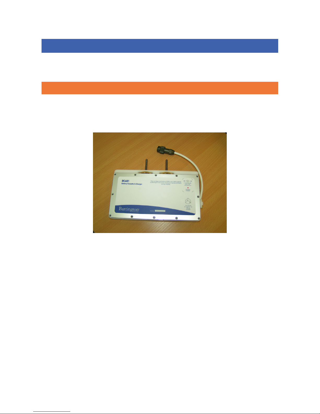
4. Battery Cassette and Charger
The gradiometer battery is a sealed Lithium Ion type and is housed in a sealed, separate cassette
(Figure 4a) which also contains the charging circuitry.
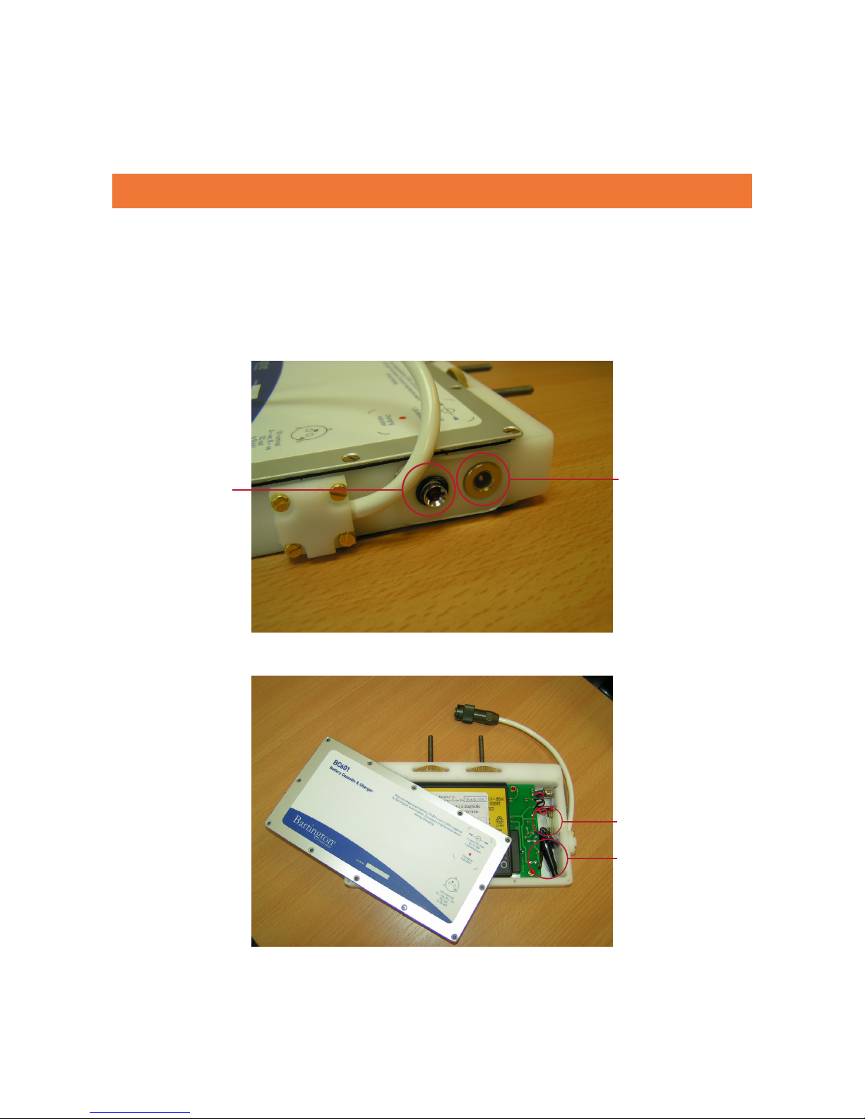
4.1. Charging the Battery
To charge the battery, connect the mains adapter supplied, or any isolated 9-18V DC supply (at
1.2A minimum), to the 2.1mm input socket (Figure 4b) for 6-8 hours. One charge will operate the
system for up to 27 hours with two gradient sensors or 36 hours with one gradient sensor.
Note: The case may become warm during charging. This is perfectly normal.
The red LED on the side of the cassette will be illuminated while the battery is being charged
(Figure 4b). At the end of the charging period the charging current will be switched off
automatically and the red LED will be extinguished. The data logger may be switched ON when the
battery is being charged, but the red LED will then not indicate the end of the charging period. The
protective cover provided for the connector should always be used when not charging.
The battery voltage is shown on the data logger display at switch-on and at the end of each
survey Grid.
Note: The battery should be recharged at the end of each surveying session.
Figure 4a: BC601 battery cassette. & charger
BARTINGTON INSTRUMENTS
Page 12 of 61 OM1800/26
Note: The battery contains electronic protection against short circuit which, if activated,
will reset after a delay of 10 minutes.
4.2. Changing the Battery
The battery or anti-surge fuse can be replaced by the operator. Remove the back cover of the
Battery Cassette. Replace the battery or fuse.
Note: When closing the Battery Cassette, ensure that an anti-surge protection fuse of the
type specified in the product brochure is in place. The fuse, and its spare, are shown in
Figure 4c.
Figure 4b: BC601 battery cassette charging input socket and red LED.
Figure 4c: BC601 battery cassette 5A fuse, and spare.
Socket
LED
Spare
Fuse
BARTINGTON INSTRUMENTS
Page 13 of 61 OM1800/26
4.3. Shipping the Battery
Caution: Batteries and equipment containing batteries should only be shipped in
accordance with local regulations. Refer to the IATA website (www.iata.org) for regulations
regarding air transport.
Caution: If there is any doubt at all as to the integrity of a battery – for example, cracked or
dented casing – then it must not be shipped. Remove it from the equipment and dispose of
it according to local regulations.
Note: Ensure that any replacement battery is of the same type as described in the product
brochure.
5. Assembly
The gradiometer system is supplied with battery and data logger attached to the beam, and
one or two separate gradient sensors as appropriate. The data logger, battery cassette and
connecting cables will normally be left attached to the beam, which is carried by the operator.
For the dual sensor version, the gradient sensors are spaced at a fixed 1m apart at the ends of
the beam.
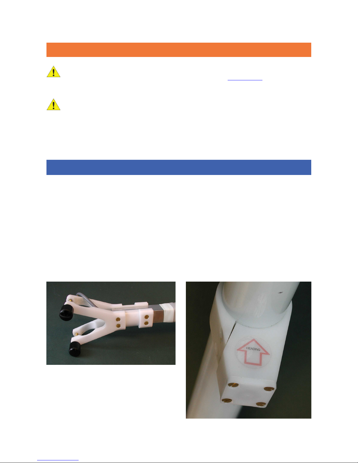
To attach a sensor, loosen the plastic knobs to release the clamp and insert the sensor at the
desired working height with the connector at the top (see Figure 5). Rotate the gradiometer(s) so
that the heading arrow on the connector junction block label (see Figure 6) of each sensor is
pointing away from the operator, in the direction of survey. Re-tighten the plastic knobs, but do
not over-tighten.
Figure 5: Gradiometer clamp showing Grad-01-1000L cable.
Figure 6: Heading direction label on Grad-01-1000L connector
junction block.

BARTINGTON INSTRUMENTS
Page 14 of 61 OM1800/26
Note: Assemble the gradiometer such that the arrows marked on the sensors are carefully
aligned to point in the direction in which the operator will walk. This will assist the
operator in pointing the arrows in the required direction during the set-up procedure. For a
single sensor the arrow should be aligned along the beam. The beam can then be pointed
in the appropriate direction during set up. Dual sensors should be mounted with the arrow
on each sensor at a right angle to the beam, with each arrow carefully aligned parallel to
the other.
Caution: Do not plug or unplug the sensor cables while the data logger is on. Doing so can
affect the sensor adjustment, or cause data logger errors.
The data logger unit has a pair of fixing holes on the underside (Figure 7) for securing the unit to
the beam. The Grad601-1 single sensor gradiometer has the sensor and data logger mounted in
front of the operator and the battery box located at the end of the beam to give a balanced
assembly as shown in Figure 3.
The Grad601-2 dual sensor gradiometer is carried with the beam across the front of the operator
with one sensor on each side as shown in Figure 2. The data logger is located with the controls
facing the operator and the battery mounted directly below it, and attached to the data logger
through the beam with two knurled captive screws.
To detach the battery from the datalogger, turn the two brass screws at the top of the battery
cassette. Ensure to hold the datalogger as it will become loose.
Should the cables need to be removed from the beam, the datalogger side of the cable can be fed
through the beam. To remove the right-hand side cable, the green/red push button will need to
be unscrewed.
Figure 7a: DL601 Data Logger underside.

BARTINGTON INSTRUMENTS
Page 15 of 61 OM1800/26
6. Connections
The functions of the sockets on the underside of the data logger are indicated in the label on the
front side of the instrument.
Caution: Only connect/disconnect the cable from data logger to sensors with the data
logger powered off. Not observing this may cause damage to the data logger.
Note: If only one sensor is used, connect it to socket 1 on the rear of the data logger. If two
sensors are used, connect the sensor to the left of the operator to socket 1 and the one to
the right to socket 2.
Note: Ensure the battery lead to the data logger is connected.
Note: The 9-way socket on the data logger is fitted with a replaceable gender changer to
greatly extend the operating life, and a protective cover which must be fitted at all times
except when downloading data.
Note: Protective caps are provided for the sensor connectors and should always be fitted
when the connectors are not in use to minimise dirt ingress.
Figure 7b: DL601 Data Logger connections guide

BARTINGTON INSTRUMENTS
Page 16 of 61 OM1800/26
7. Grad601-2 Carrying Harness
The harness supplied with the dual sensor gradiometer is shown in Figure 8. This completely
relieves the operator’s arms of the weight of the gradiometer system, allowing easy operation of
the controls.
The harness comprises a lightweight, soft, padded shoulder harness, with a bag to contain a
balance weight (sand or water), attached to an abdominal spacer by adjustable webbing straps
through two replaceable plastic links.
The gradiometer can be quickly attached to and detached from the harness using two simple
sprung hooks. This makes it possible to use more than one harness (and operator) with one
gradiometer.
The sprung cradles on the abdominal spacer are clipped onto the bearings located on the beam.
The webbing straps allow the height of the beam to be adjusted to suit the operator. To remove
the gradiometer from the harness, use a thumb on each hand to spring open the cradle. All parts
may be separated for repair or replacement and may be cleaned in water.
8. Instrument Stands
The gradiometers each have an integral prop attached to the beam for parking the gradiometer
when not in use.
Figure 8: Grad601-2 dual sensor gradiometer carrying harness.

BARTINGTON INSTRUMENTS
Page 17 of 61 OM1800/26
9. Setting Up
The gradiometer must be set up using an automated procedure to help it adjust to the
environment in which it is to be operated. The same procedure also removes alignment errors
and scaling differences between the sensing elements forming the gradient sensor.
This operation is to be carried out over a magnetically quiet area on or near the site to be
surveyed.
Details of the procedure are given in Checking and Adjusting the Sensors. A training video is also
available.
Note: After assembly, switch on the Grad601 for a period of at least 15 minutes before
carrying out the setting up procedure. During this warm-up period the instrument must
be left in the environment in which it will be operating. For example, if it will be used in the
sun, let it warm up in the sun rather than in the shade.
Note: The alignment should be checked at intervals over the course of a day by returning
to the quiet area and measuring the variation in magnetic gradient when rotating the
gradiometer by 180 degrees. The setting up procedure should be repeated as necessary.
Note: This procedure, which takes only a few minutes, must also be repeated whenever
the sensors are adjusted for height relative to the beam. It will remove any offset error
generated by changes in the position of the battery and other magnetic components
relative to the sensor elements.
10. Keypad Operation and Display
The Grad601 Data Logger DL601 (see Figure 9) has 6 keys to set parameters and control the
operation. A two-line, 20-character display shows the menus, results etc. The functions of the
keys are as follows:
Figure 9: DL601 Data Logger control panel.
BARTINGTON INSTRUMENTS
Page 18 of 61 OM1800/26
Key Function
ON/OFF Controls the power to the unit and sensors. Press to alternately apply
and remove power. When the display is blank, the power is OFF. When the
display is active, the power is ON. A short delay is incorporated.
Caution: If power is removed during memory access operations when
the screen displays: ‘Saving’, ‘Deleting’, or ‘Please Wait’, then memory
corruption can occur and data loss is possible. See Power Loss for
more details.
ENTER Starts the operation of the menu item displayed on the top line against the
> cursor. It is also used to progress to the next operation if requested by
a displayed message when static information is shown, or to confirm the
operator’s selection. If in doubt, press ENTER to continue and ESC to go back.
ESC
(Escape)
Exits a procedure and returns to the previous menu or operation.
(up/
down
arrows)
Scroll through the menus to set the required option to the top cursor line,
before starting the operation with the ENTER key.
STEP Step through the available options for each of the operating parameters.
Note: With the exception of the ON/OFF key, the required action occurs only when a key is
released after being pressed.
Note: External push buttons are provided on the beam for use as optional ENTER (green)
and ESC (red) keys. These are particularly useful in the survey mode and during setting up.
They provide control of the data collection, and interruption during surveys and setting up
without moving the hand from the beam.
Note: A menu may offer an action which is not valid at that time, for example moving back
one line when at the start of the first line. If a non-valid menu selection is made then the
data logger will bleep and take no action.
11. Grid Mode
Connect the data logger to the gradient sensors and battery, and then press and hold the ON/OFF
switch until the display is activated. At switch-on the display will show the title screen with the
program version and battery voltage for a few seconds, before switching to the Mode Selection
Menu. You can then select either GRID MODE or NMEA MODE.
Note: To change between Grid and NMEA Modes, the data logger must be restarted by
turning off/on.

BARTINGTON INSTRUMENTS
Page 19 of 61 OM1800/26
11.1. Main Menu: Grid Mode
The items in the Grid Mode main menu are as follows:
• Start survey
• Start scan
• Output data
• Delete data
• Set parameters
• Adjust gradiometer
• System reset
The two-line display will show only two items at a time. The first two items in the Grid Mode main
menu will be shown as:
>Start survey
Start scan
The > prompt in the top line shows the menu item that will be activated when the ENTER key is
pressed. The second line shows the next item in the list. Scroll down and up through the list,
one line at a time, by pressing the down and up arrow keys. Hence, pressing the down arrow will
change the display to:
>Start scan
Output data
After completing each task the program returns to this main menu.
Note: Always return to this menu before pressing the ON/OFF switch to turn off the power.
Note: Before selecting Start survey or Start scan, select Set parameters to set the number of
sensors being used and all other variables to ensure correct operation.
Note: When using the instrument for the first time, if the Set parameters menu shows
invalid values or is incomplete, then return to the main menu and select System reset. This
sets default values into the operating parameters, deletes the memory and resets the
memory pointers. The parameters can then be set to the values required by the operator.

BARTINGTON INSTRUMENTS
Page 20 of 61 OM1800/26
11.2. Set Parameters Menu: Grid Mode
From the main menu select Set parameters and press ENTER. This will give a further menu with
default parameters set as shown in the table below. Use the arrow keys to select each item in
turn, and then press the STEP key to step through the available options for that parameter.
Option Default Function
Pace : 1.8m/s Select the walking pace of the operator: 0.5 to 2m/s in
0.1m/s increments, or Single shot.
Gridsize : 30x30 Select the size of Grid: 10x10, 20x20, 30x30 or 40x40m.
Start : North Select the starting direction of the Grid: N, NE, E, SE,
S, SW, W or NW.
Paern : Zig-Zag Select the traverse pattern to be followed: Parallel or
Zigzag.
Lines/m : 1 Select the required number of data lines per metre: 1,
2 or 4.
Note: For a dual sensor system the spacing
is fixed at 1 metre so the operator will walk
(traverse) at 2m intervals to record data at 1
line/m. For 2 or 4 lines/m a special traverse
pattern is required with a 2m repeat. See Survey
Mode (Grid Mode) and Survey Operation (Grid
Mode) for details.
Samples/m : 4 Select the number of samples per metre along each
line: 1, 2, 4 or 8.
Note: A density of up to 8 samples/m is available
for 10x10, 20x20 and 30x30m Grids. A density
of up to 4 samples/m is available for Grids of
40x40m.
Range : 100nT Select the full scale range of 100nT (resolution 0.03nT)
or 1000nT (resolution 0.1nT).
Audio : On Select the audio output for scanning and survey
operations: Off or On.
Volume : High Select volume: High or Low.
Table of contents
Other Bartington Measuring Instrument manuals

Bartington
Bartington Mag628 User manual

Bartington
Bartington Mag613 User manual

Bartington
Bartington Grad-13 Series User manual

Bartington
Bartington Mag-01 User manual

Bartington
Bartington MS2 User manual

Bartington
Bartington Mag-01H User manual

Bartington
Bartington Mag690 User manual

Bartington
Bartington Mag-01 User manual

Bartington
Bartington Grad-13 Series User manual

Bartington
Bartington MS3 User manual


