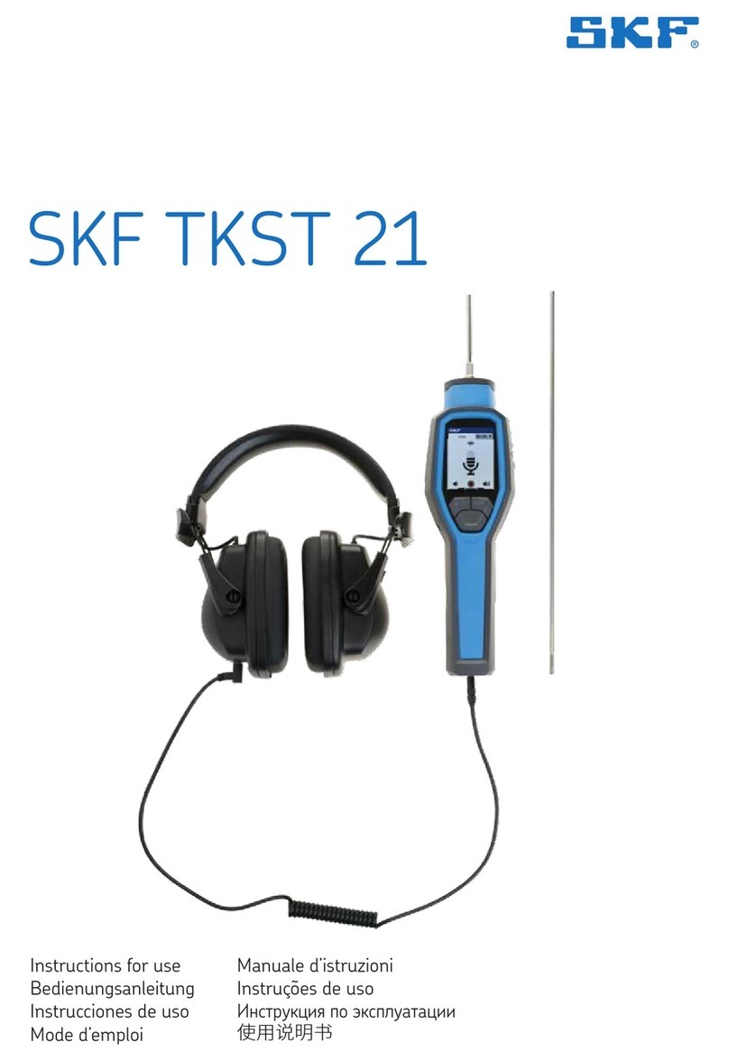
SKF TKTL 21 User manual

Instructions for use
Bedienungsanleitung
Instrucciones de uso
Mode d’emploi
Manuale d’istruzioni
Instruções de uso
Инструкция по эксплуатации
使用说明书
SKF TKTL 21


1EN
EN English 2
DE Deutsch 16
ES Español 30
FR Français 44
IT Italiano 58
PT Português 72
RU Русский 86
ZH 中文100

2 EN
Safety recommendations...........................................................3
EC Declaration of conformity .....................................................4
1. Introduction........................................................................5
2. Quick start..........................................................................5
3. Features .............................................................................5
4. Technical data.....................................................................6
5. Front panel and button description .....................................8
6. Display overview...............................................................10
7. Menu overview .................................................................11
8. Measurement settings ......................................................12
9. Maintenance.....................................................................13
9.1 Storage & cleaning.................................................................13
9.2 LCD error messages...............................................................13
9.3 Batteries ..................................................................................13
10. Notes ...............................................................................14
11. Emissivity table.................................................................15
12. Spare parts ......................................................................15
Table of contents
Original instructions

3EN
WARNING LASER RADIATION
DO NOT STARE INTO BEAM
CLASS 2 LASER PRODUCT
Max. Output: <1mW Wavelenght: 635-660nm
Complies with 21 CFR Chapter 1, subchapter J
Safety recommendations
• Always read and follow the operating instructions for use.
• Never stare directly into the laser source. Class II laser product.
• Never aim the laser beams into anyone’s eyes.
• Never open the instrument.
• Never use the instrument under rain or very wet conditions
• Not for intrinsically safe area
• All repair work should be taken care of by an SKF repair shop.
• Here is a table of hazardous substance name and concentration
for TKTL 21:
Part
name
Hazardous Substances
Lead Mercury Cadmium Hexavalent
Chromium Polybrominated
biphenyls Polybrominated
diphenyl
ethers
(Pb) (Hg) (Cd) (Cr(VI)) (PBB) (PBDE)
Laser
module × • • • • •
The table is prepared in accordance with the provisions of SJ/T11364.
•: Indicates that said hazardous substance contained in all of the
homogeneous materials for this part is below the limit requirement
of GB/T 26572.
×: Indicates that said hazardous substance contained in at least one of
the homogeneous materials used for this part is above the limit
requirement of GB/T 26572.

4 EN
EC Declaration of conformity
TKTL 21
We, SKF MPT, Meidoornkade 14, 3992 AE Houten, The Netherlands
herewith declare under our sole responsibility that the products
described in these instructions for use, are in accordance with the
conditions of the following Directive(s):
EMC DIRECTIVE 2014/30/EU
and are in conformity with the following standards:
EN 61326-1:2013, EN 61326-2-2:2013
Emission: CISPR 11:2009+A1: 2010, Class B
Immunity: IEC 61000-4-2:2008
IEC 61000-4-3:2010
IEC 61000-4-8:2009
Laser standards: 21 CFR, ch 1-J
WEEE: European Directive 2012/19/EU
RoHS: RoHS DIRECTIVE (EU) 2015/863
CE requirements: CE certified
Houten, The Netherlands, February 2021
Mrs. Andrea Gondová
Manager Quality and Compliance

5EN
1. Introduction
The SKF TKTL 21 is a portable, lightweight multi- functional
instrument for safely measuring temperatures at a distance.
Simply aim and pull the trigger and the temperature is shown on
the display. Users can also measure contact temperatures using the
probe supplied.
This feature rich instrument also has the facility to store measured
values such as Maximum, Minimum, Difference, Average, High Alarm,
Low Alarm, Emissivity setting.
2. Quick start
1. Simply aim the thermometer at the measure target with Lens (7)
and press Meas. key (6) to display the surface temperature.
2. The Distance:Spot is 30:1.
The eight laser points are the reference for the target spot size.
Please make sure the target area is within the field of view.
3. Features
• LCD color display
• 8 laser targeting
• Type-K thermocouple probe
• Adjustable emissivity
• High accuracy
• Fast response time
• DS ratio of 30:1
As the distance (D) from the object increases, the spot size (S) of the
area measured by TKTL 21 becomes larger.
The relationship between distance and each unit is listed below.
The spot size indicates 90% measured energy.
Laser FOV
D:S
=
30:1
Distance (D) to Spot (S) ratio
5cm@1,5m 10cm@3,0m
D
S
2in@60in 4in@120in

6 EN
4. Technical data
Designation TKTL 21
Temperature range -60 to 760 °C (-76 to 1 400 °F)
Temperature range using probe -64 to 1 400 °C (-83 to 2 552 °F)
Probe supplied TMDT 2-30, suitable for use up to
900 °C (1 650 °F)
Probe types suitable K type probes
Environmental limits
Operation 0 to 50 °C (32 to 122 °F)
10 to 95% R.H.
Storage -10 to 60 °C (14 to 140 °F)
10 to 95% R.H.
Full range accuracy
Tamb = 25°C Tobj = 15 to 35 °C, +/- 1.0 °C (1.8 °F)
Tamb = 23 +/- 3°C Tobj = 0 to 760 °C, +/-2% of reading or
2 °C (4 °F) whichever is greater
Tamb = 23 +/- 3°C Tobj = -60 to 0 °C, +/- (2 + 0.05/°) °C
Tamb = 23 +/- 6°C With probe: , +/- 1% of reading or
1°C (1.8°F) whichever is greater
Response time 1 000 msec (90%)
Optics Sense emitted, reflected and transmitted
energy.
Display Color LCD
User selectable backlit display No, permanently ON
Displayed resolution 0.1 °C/F from -83.2~999.9,
otherwise 1 °C/F
Distance to spot size 30:1
Spectral response 8-14 µm
User selectable laser yes, On/off
User selectable LED No, permanently ON
Buttons 3 buttons and 1 trigger.
Function as per instructions for use
Measurement modes Max, min, differential, average,
probe/IR dual temperature modes
Alarm modes High and low level alarm level with
warning bleep
Emissivity variable 0.1-1.0
Laser pointers 8 laser dots
Laser wavelength 635 - 660 nm
Laser Class 2
Maximum laser power 1 mW
Dimensions 119.2 × 171.8 × 47.5 mm
(4.7 × 6.8 × 1.9 in)
TL1 Carrying case dimensions 530 × 85 × 180 mm (20.9 ×3.4 ×7.0 in)
Weight (including case) 1 150 g (2.54 lb)
7EN
Designation TKTL 21
Battery 2 × AAA Alkaline type IEC LR03
Battery lifetime Min. 30 hours continuous use without
laser.
Min. 3 hours continuous use with laser
and white LED
Switch off IR mode automatic after 60 seconds
after trigger is released.
Probe mode automatic after 12 minutes

8 EN
5. Front panel and button description
6
5
1
2
3
4
Item Description
1LCD
2 Mode key
3 Down key
4 Up key
5 Thermocouple socket
6 Meas. key

9EN
7
9
10
8
Item Description
7 Infrared lens
8 LED
9 Multi-beams
10 Battery cover

10 EN
6. Display overview
Default screen
Multi-Beams: spicify the apprximate measurement area for better targetting

11EN
7. Menu overview
• Press Mode key (2) for
scrolling more display
function as follows.
• Here will show the
emissivity data.
(The default emissivity
is 0.95.)
• Press Mode key (2),
then press Up key (4) or
Down key (3) to set the
emissivity, then press
Mode key (2) to confirm
it. The emissivity can be
changed from 0.10 (10E)
to 1 (100E).
• Press Mode key (2) for the Maximum (MAX), Minimum (MIN),
Different between MAX and MIN (DIF) and Average (AVG) modes.
During the measurement, the special modes reading will be
displayed beside the mode icon.
• Press Up key (4) or Down key (3) to change the High Alarm (HAL)
or Lo Alarm (LAL), then press Meas. key (6) to confirm it.
When the reading is outside the High Alarm (HAL) or Lo Alarm
(LAL) limit. The High or Low icon will flash and you will hear a
beep sound.
• Connect the thermocouple with Thermocouple socket (5) and
put the probe in/on the target, the thermometer will display the
temperature automatically without pressing any button. To see
the minimum or maximum data during the probe measurement,
please hold down the Up key (4) or Down key (3).
BEWARE:
• Affter measuring high temp, the probe may remain HOT for
a while.
** The thermometer will automatically shut off if left idle for more
than 60 sec, unless in PRB mode. (In PRB mode, it will shut off if
left idle for more than 12 minutes.)

12 EN
8. Measurement settings
• In E, MAX, MIN, DIF, AVG mode:
Press Up key (4) for LOCK mode ON/OFF.
The lock mode is particularly useful for continuous monitoring
of temperatures for up to 60 minutes.
• Press Down key (3) for °C or °F transferred.
• In MAX, MIN mode: Hold on the Meas. key (6).
The Bar display indicates the measuring temperature.
The bar shows RED color when the reading is close to maximum
value, and shows BLUE when close to minimum.
While the temperature is between the maximum and minimum,
the bar will display in YELLOW.
• Backlight: LCD Backlight: always on.
• In all modes: First hold on the Meas. key (6) and press
Down key (3) for laser Class II function ON/OFF.

13EN
9. Maintenance
9.1 Storage & cleaning
It should be stored at room temperature. The sensor lens is the most
delicate part of the thermometer. The lens should be kept clean at all
times, care should be taken when cleaning the lens using only a soft
cloth or cotton swab with water or medical alcohol, allowing the lens
to fully dry before using the thermometer. Do not submerge any part
of the thermometer.
9.2 LCD error messages
The thermometer incorporates visual diagnostic messages as follows:
‘Hi’ or ’Low’ is displayed when the temperature being measured is
outside of the settings of HAL and LAL.
‘Er2’ is displayed when the thermometer is exposed to rapid changes
in the ambient temperature.
‘Er3’ is displayed when the ambient temperature exceeds
0 ºC (32 °F) or +50 ºC (122 °F). The thermometer should be
allowed plenty of time (minimum 30 minutes) to stabilize to the
working/room temperature.
Error 5~9, for all other error messages it is necessary to reset the
thermometer. To reset it, turn the instrument off, remove the battery
and wait for a minimum of one minute, reinsert the battery and turn
on. If the error message remains please contact SKF.
‘Hi’ or ’Lo’ is displayed when the temperature being measured is
outside of the measurement range.
9.3 Batteries
The thermometer incorporates visual low battery indication as
follows:
• ‘Battery OK’: measurements are possible.
• ‘Battery Low’: battery needs to be replaced,
measurements are still possible.
• ‘Battery Exhausted’: measurements are not possible.
When the ‘Low Battery’ icon indicates the battery is low, the battery
should be replaced immediately with AAA, 1.5V batteries.
Please note: It is important to turn the instrument off before
replacing the battery otherwise the thermometer may malfunction.
Dispose of used battery promptly and keep away from children.
If the device is not to be used for a long time, turn the power off,
remove and store the batteries in a cool, dry place.

14 EN
10. Notes
How does Infrared work?
Infrared thermometers measure the surface temperature of an
object. The unit’s optics sense emitted, reflected, and transmitted
energy, which is collected and focused onto a detector.
The unit’s electronics translate the information into a temperature
reading, which is displayed on the unit.
The laser is used for aiming purpose only.
• Field of View
Make sure the target is larger than the unit’s spot size.
The smaller the target, the closer you should be.
When accuracy is critical, make sure the target is at least twice as
large as the spot size.
• Distance & Spot Size
As the distance (D) from the object increases, the spot size (S) of the
area measured by the unit becomes larger.
See figure at the beginning of this manual.
• Locating a hot Spot
To find a hot spot aim the thermometer outside the area of interest,
then scan across with an up and down motion until you locate hot
spot.
• Reminders
- Do not use the unit to measure shiny or polished metal
surfaces (stainless steel, aluminum, etc.). See Emissivity.
- The unit can not measure through transparent surfaces such
as glass. It will measure the surface temperature of the glass
instead.
- Steam, dust, smoke, etc., can prevent accurate measurement
by obstructing the unit’s optics.
• Emissivity
Emissivity is a term used to describe the energy-emitting
characteristics of materials.
Most (90% of typical applications) organic materials and painted or
oxidized surfaces have an emissivity of 0.95 (pre-set in the unit).
Inaccurate readings will result from measuring shiny or polished
metal surfaces. To compensate, cover the surface to be measured
with masking tape or black paint. Allow time for the tape to reach the
same temperature as the material underneath it.
Measure the temperature of the tape or painted surface.

15EN
11. Emissivity table
Substance Thermal
emissivity
Substance Thermal
emissivity
Asphalt 0,90 to 0,98 Cloth (black) 0,98
Concrete 0,94 Human skin 0,98
Cement 0,96 Leather 0,75 to 0,80
Sand 0,90 Charcoal
(powder)
0,96
Earth 0,92 to 0,96 Lacquer 0,80 to 0,95
Water 0,92 to 0,96 Lacquer (matt) 0,97
Ice 0,96 to 0,98 Rubber (black) 0,94
Snow 0,83 Plastic 0,85 to 0,95
Glass 0,90 to 0,95 Timber 0,90
Ceramic 0,90 to 0,94 Paper 0,70 to 0,94
Marble 0,94 Chromium
oxides 0,81
Plaster 0,80 to 0,90 Copper oxides 0,78
Mortar 0,89 to 0,91 Iron oxides 0,78 to 0,82
Brick 0,93 to 0,96 Textiles 0,90
12. Spare parts
Designation Description
TMDT 2-30 Contact probe
TDTC 1/X General toolcase without inlay, size X

16 DE
Sicherheitshinweise ................................................................17
CE Konformitätserklärung .......................................................18
1. Einleitung .........................................................................19
2. Kurzanleitung ...................................................................19
3. Merkmale .........................................................................19
4. Technische Daten..............................................................20
5. Bedien- und Messelemente...............................................22
6. Display .............................................................................24
7. Menü ...............................................................................25
8. Messeinstellungen ............................................................26
9. Instandhaltung .................................................................27
9.1 Aufbewahrung & Reinigung..................................................27
9.2 LCD-Fehlermeldungen ..........................................................27
9.3 Batterien..................................................................................27
10. Hinweise...........................................................................28
11. Emissivitätstabelle............................................................29
12. Ersatzteile ........................................................................29
Inhalt
Übersetzung der Original-Bedienungsanleitungen

17DE
WARNUNG: STRAHLEN EINES LASERS
NICHT IN DEN STRAHL BLICKEN
LASERPRODUKT DER KLASSE 2
Max. Output: <1mW Wellenlänge: 635-660nm
Gemäß Kapitel 1, 21 CFR; Unterkapitel J
Sicherheitshinweise
• Lesen und befolgen Sie die Bedienanleitung.
• Nie direkt in die Laserquelle sehen. Laserprodukt der Klasse II.
• Laserstrahl nie direkt auf die Augen von Personen richten.
• Gerät nicht öffnen oder auseinandernehmen.
• Gerät nicht bei Regen oder starker Feuchtigkeit betreiben.
• Nicht für eigensichere Bereiche geeignet.
• Reparaturarbeiten sind von einem SKF Reparatur Service Center
durchzuführen.
• Gefahrstoffe und Konzentrationen für TKTL 21:
Teil
Gefahrstoff
Blei Quecksilber Cadmium Sechswertiges
Chrom Polybromierte
Biphenyle Polybromierte
Diphenyl-
ether
(Pb) (Hg) (Cd) (Cr(VI)) (PBB) (PBDE)
Laser-
modul × • • • • •
Die Tabelle wurde gemäß SJ/T11364 zusammengestellt.
• Der in allen homogenen Materialien dieses Teils enthaltene Gefahrstoff
liegt unter dem Grenzwert gemäß GB/T 26572.
× Der zumindest in allen homogenen Materialien dieses Teils enthaltene
Gefahrstoff liegt über dem Grenzwert gemäß GB/T 26572.

18 DE
CE Konformitätserklärung
TKTL 21
Die SKF MPT, Meidoornkade 14, 3992 AE Houten, Niederlande
erklärt hiermit unter unserer alleinigen Verantwortung, dass die in
dieser Gebrauchsanweisung beschriebenen Produkte den folgenden
Richtlinien und Normen entsprechen:
EMV-RICHTLINIE 2014/30/EU
außerdem stimmen sie mit den folgenden Normen überein:
EN 61326-1:2013, EN 61326-2-2:2013
Emissionen: CISPR 11:2009+A1: 2010, Klasse B
Störfestigkeit: IEC 61000-4-2:2008
IEC 61000-4-3:2010
IEC 61000-4-8:2009
Lasernormen: 21 CFR, Kap. 1-J
WEEE: Europäische Richtlinie 2012/19/EU
RoHS: RoHS-RICHTLINIE (EU) 2015/863
CE-Anforderungen: CE-zertifiziert
Houten, in den Niederlanden, Februar 2021
Mrs. Andrea Gondová
Manager Quality and Compliance
Other manuals for TKTL 21
1
Table of contents
Languages:
Other SKF Measuring Instrument manuals