Bartington Grad-13 Series User manual

Operation Manual for
Grad-13 Digital Three-Axis Magnetic
Gradiometer

BARTINGTON INSTRUMENTS
DCN1040 Page 2 of 39 OM3100/2
Table of Contents
1. About this Manual 4
1.1. Symbols Glossary 4
2. Safe Use 4
3. Introduction 4
4. Grad-13 Digital Three-Axis Fluxgate Gradiometer 5
4.2. Grad-13 Battery Box & Multiplexing box 6
4.3. Grad-13 Cable Assembly 6
5. Grad-13 Battery Box 7
5.1. Functional Description 7
5.2. The Battery Box Front Panel 7
5.3. Power Supply 8
6. The Grad-13 8 Port Multiplexing Box 9
6.1. Functional Description 10
6.2. The 8 Port Multiplexing Box Front Panel 10
6.3. Power supplies 12
6.4.Fuses 14
7. Installation of the Grad-13 14
7.1. Unpacking 14
7.2. Orientation 14
7.3. Mounting 14
7.4. Connecting 15
7.5. Connecting Custom Systems 15
8.
Operating
I
ns
t
r
u
c
t
i
o
ns 15
8.1. Operation 15
8.2. Visual Grad-13 Software Instructions 15
8.3. MultiGrad13 Software 27
9. Storage 36

BARTINGTON INSTRUMENTS
DCN1040 Page 3 of 39 OM3100/2
10. Servicing & Maintenance 37
11. End of Life Disposal 37
11.1. Waste Electrical and Electronic Equipment (WEEE) Regulations 37
Appendix A: Guidance for Connection to Mains Supply 38

BARTINGTON INSTRUMENTS
DCN1040 Page 4 of 39 OM3100/2
1. About this Manual
This document describes the installation, operation and maintenance of the Grad-13 digital
three axis fluxgate gradiometer from Bartington Instruments. It should be read in conjunction
with the product brochure DS3100, which can be found on the product page on the Bartington
Instruments website at www.bartington.com. Outline drawings are also available on this page.
Note that failure to follow the instructions in this manual may invalidate your product’s warranty.
If in doubt, do not hesitate to contact Bartington Instruments.
Bartington Instruments cannot advise on the integration of this equipment with any third party
products.
1.1. Symbols Glossary
The following symbols used within this manual call your attention to specific types of
information:
WARNING: Indicates a situation in which serious bodily injury or death could result if the
warning is ignored.
Caution: Indicates a situation in which bodily injury or damage to your instrument, or both,
could result if the caution is ignored.
Identifies items that must be disposed of safely to prevent unnecessary damage to the
environment.
Note: Provides useful supporting information on how to make better use of your purchase.
2. Safe Use
WARNING: These products are not qualified for use in explosive atmospheres or life
support systems. Consult Bartington Instruments for advice.
3. Introduction
The Grad-13 is a three axis digital fluxgate gradiometer available in two versions, the Grad-13-L
for land operation and the Grad-13-S that is submersible to 200 metres.
This unit is comprised of two three axis fluxgate magnetometers, one at either end of a
mechanically stable beam. Each cluster of fluxgates is arranged such that the centres of the
three magnetic axes coincide at a common point. The vector magnetic field experienced by each
of the 3 magnetic axes is converted to an RS422 digital output.
BARTINGTON INSTRUMENTS
DCN1040 Page 5 of 39 OM3100/2
As well as magnetic field gradient data, the RS422 output also includes 3 axis accelerometer
data, as well as temperature information. Battery and multiplexing boxes are available to power
and convert the Grad-13 output.
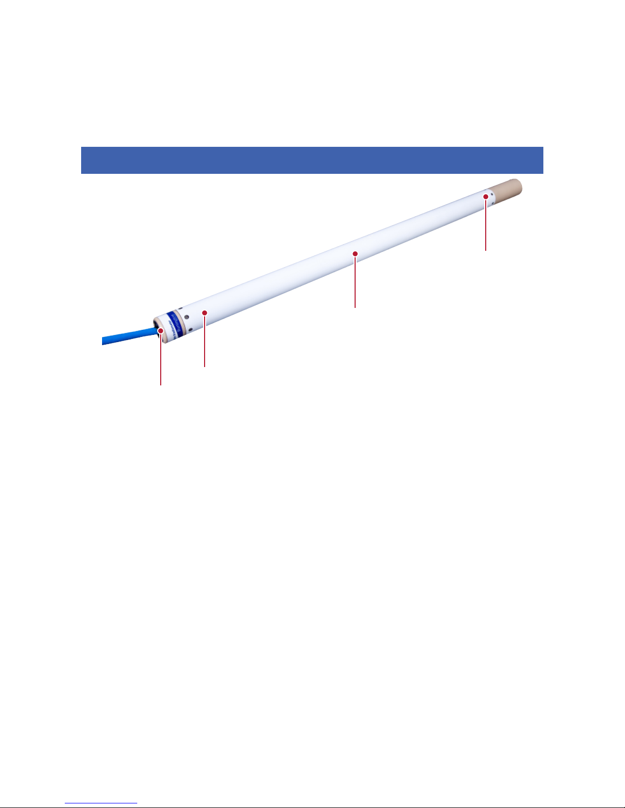
4. Grad-13 Digital Three-Axis Fluxgate Gradiometer
Figure 1: Grad-13 Digital Three-Axis Fluxgate Gradiometer
Key
1. Cable to Grad-13 Battery/Multiplexing Box
2. Three-axis reference magnetometer
3. Three-axis Accelerometer
4. Three-axis sensing magnetometer
Note: Refer to the outline drawing DR3344 on the product webpage for further information.
The magnetometer assembly is supported on shock resistant mounts inside an electrically
isolated carbon fibre composite tube having ‘O’ ring seals at each end. Power is applied to the
unit and digital signals are output via an environmentally sealed connector.
The electronics are designed to minimise offset, scaling and orthogonality errors.
A temperature sensor and a test coil with a precision current source are included. Power supply
is provided using the Grad-13 Battery or Multiplexing Box, and basic software is provided to
interpret the RS422 digital data.
1
2
3
4

BARTINGTON INSTRUMENTS
DCN1040 Page 6 of 39 OM3100/2
4.2. Grad-13 Battery Box & Multiplexing box
Bartington Instruments can provide two options for powering the Grad-13 and converting the
signal output to either USB or ethernet output. These options are the Grad-13 Battery Box or the
Grad-13 Multiplexing box.
3.2.1. Grad-13 Battery Box
The Grad-13 Battery Box converts the signal from the Grad-13 to USB output. It is designed to be
used with one, or two gradiometers. See Section 5. Grad-13 Battery Box for further information.
3.2.2. Grad-13 Multiplexing Box
The Grad-13 Multiplexing Box converts the signal from the Grad-13 to ethernet output. It is
designed to be used with up eight gradiometers. See Section 6. Grad-13 8-Port Multiplexing Box
for further information.
4.3. Grad-13 Cable Assembly
Note: See drawing DR3344 (Land version) and DR3286 (Marine version) on the product
webpage.
The cable supplied with the Grad-13 for connection to the Grad-13 battery box is appropriate
to and dependent upon the version it is supplied for, i.e. Land or Marine. The polarity of the
connectors prevents incorrect connection.
To connect the Grad-13S variant to the battery box, an accessory cable, the Grad-13S
Underwater to Land Extension Cable, is required.
BARTINGTON INSTRUMENTS
DCN1040 Page 7 of 39 OM3100/2
5. Grad-13 Battery Box
This section describes the installation and operation of the Grad-13 Battery Box.
5.1. Functional Description
The Grad-13 battery box allows connection of one or two Bartington Instruments Grad-13
gradiometers. It powers the gradiometer and converts the RS422 output to USB. A rechargeable
battery is built into the box and a dedicated charger is provided with the unit. A dedicated USB
cable is also provided to provide connectivity to a computer.
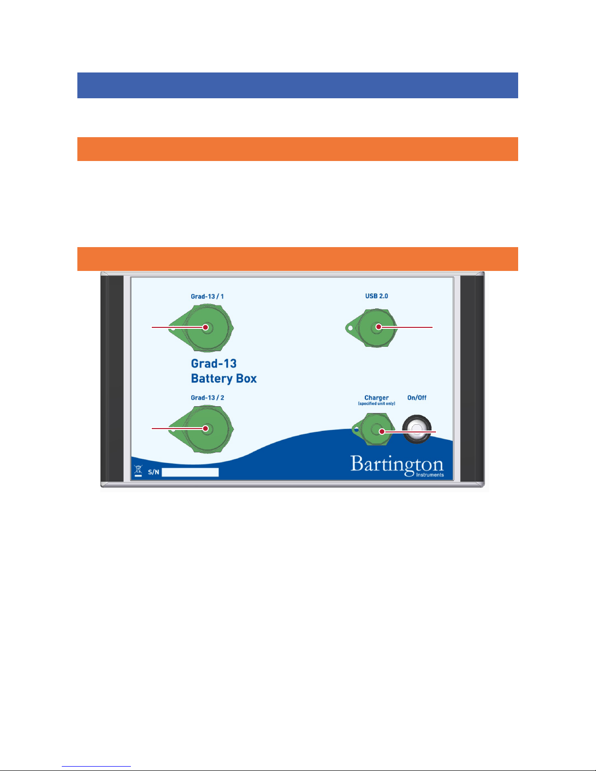
5.2. The Battery Box Front Panel
Figure 2:The Grad-13 Single Battery Box
Key
1: Connector for connection to Grad-13 gradiometer
2: Connector for connection to PC via USB 2.0
3: ON/OFF power switch with power-on indicator
4: Charger connector for connection to mains power.
Note: See the outline drawing DR3911 on the product webpage for further information.
1
24
3
BARTINGTON INSTRUMENTS
DCN1040 Page 8 of 39 OM3100/2
The units are housed in a polycarbonate enclosure. Connectors on the front panel provide
connection to the Grad-13 and to a PC for digital output, with a socket for the charger input.
5.3. Power Supply
The battery box contains a lithium ion battery with a nominal voltage of 26V and an energy
density of around 72Wh. It is capable of powering a single Grad-13 for up to 16 hours, and two
Grad-13s for up to eight hours.
The On/Off power switch light will flash when the battery is around 80% discharged. The length
of time taken to discharge to this level depends upon the number of gradiometers connected, the
battery age, and the battery temperature.
WARNING: The mains supply to the charge must be switched off before connecting or
disconnecting the charger to the Grad-13 battery box.
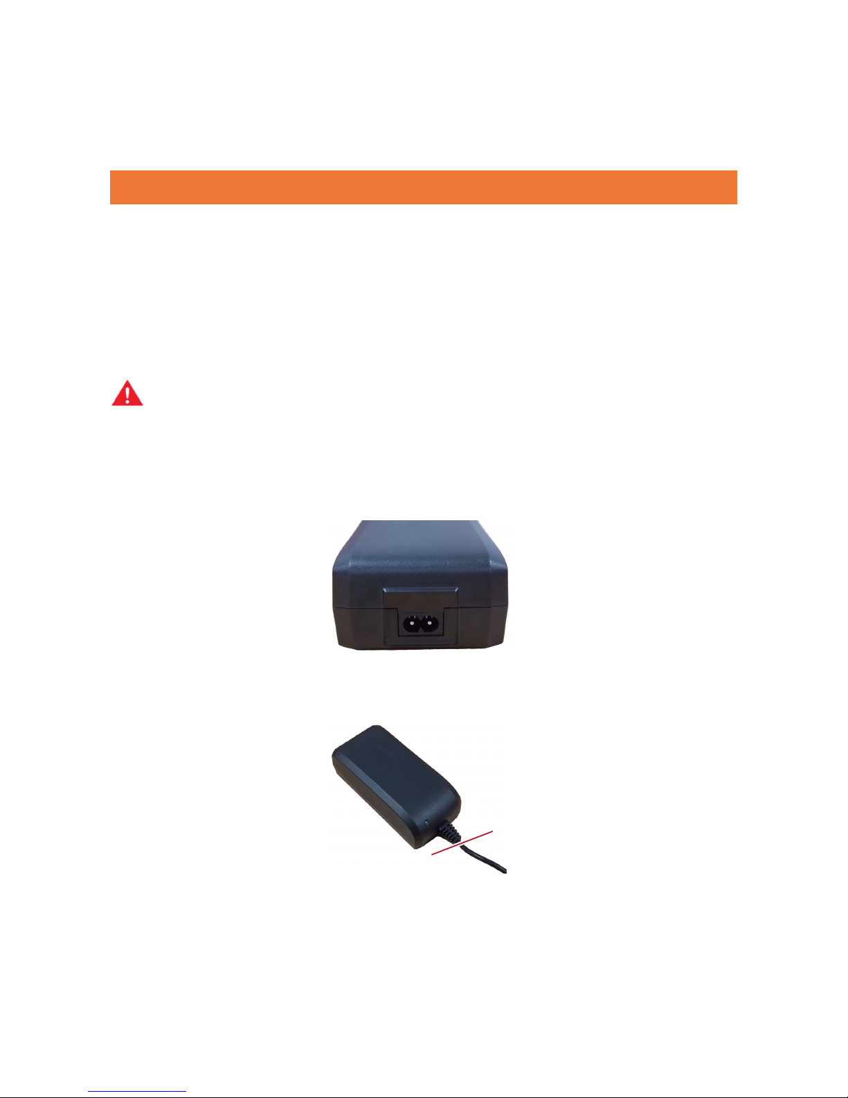
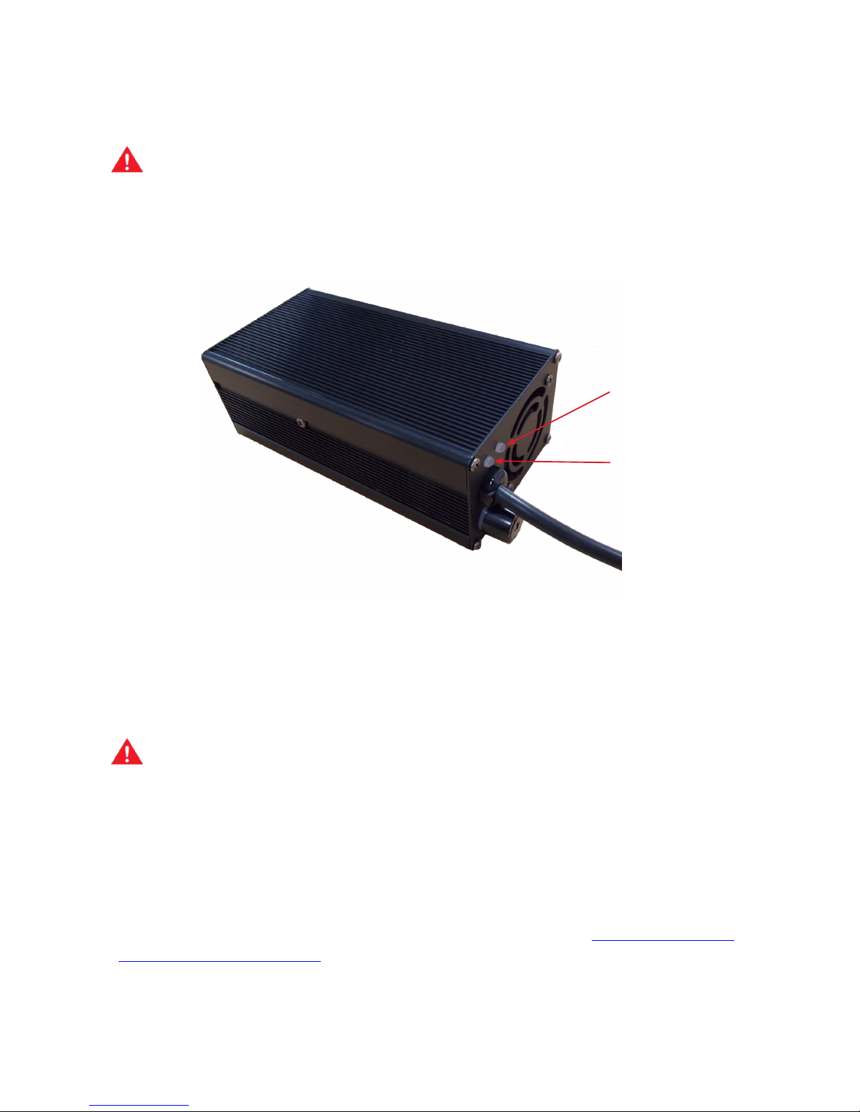
5.3.1. Charging
The battery charger supplied with the battery box is shown below. The mains input socket is at
the rear. The charge input voltage range is 100-240V, so no voltage selector switch is required.
The front panel of the changer includes a yellow/green LED, which indicates power and charging
status.
At swtch-on the LED flashes yellow/green and then indicates the following statuses.
LED

BARTINGTON INSTRUMENTS
DCN1040 Page 9 of 39 OM3100/2
LED Indication Status
Yellow Standby mode
Yellow/green flashing Outside of valid temperature (wait)
Green flashing Charging
Green At least 80% charged. Wait for one further
hour for full charge.
Yellow flashing Error
Battery charging time from flat is around three hours, but charging for longer (typically
overnight) is acceptable as the charger will switch to standby mode when the battery has
reached full charge.
6. The Grad-13 8 Port Multiplexing Box
This section describes the installation and operation of the Grad-13 8 Port Multiplexing Box. It
should be read in conjunction with the Grad-13 product brochure which can be found on the
Bartington Instruments website.
Figure 3:The Grad-13 8 Port Multiplexing box
6.1. Functional Description
The Grad-13 Multiplexing box is designed to allow connection of up to eight Bartington
Instruments Grad-13 gradiometers simultaneously. It provides power, and acts as a junction

BARTINGTON INSTRUMENTS
DCN1040 Page 10 of 39 OM3100/2
box for the RS422 data outputs. The multiplexing box will combine and transmit the received
RS422 data from each gradiometer on a single Ethernet connection to an external laptop or
data recording system. A fully charged battery will run the system with eight gradiometers for
approximately 8 hours.
The multiplexing box has a removable lid for use during storage and transport.
The Network LED indicates that the system is connected to a network.
The Low Power LED flashes to indicate that the battery is nearing the end of its charge. Battery
life remaining after this point is dependent upon the number of gradiometers in use.
The External Power Input connector allows an external battery to be connected to the unit, if the
internal batteries become exhausted. This feature is currently under development.
6.2. The 8 Port Multiplexing Box Front Panel
Figure 4:The Grad-13 8 port multiplexing box front panel
Key
1: Grad Connectors and LEDs: These 8 connectors provide power and data signals
for each Grad-13 that is connected. Each has an associated green LED which
11
2 3
4 6
5

BARTINGTON INSTRUMENTS
DCN1040 Page 11 of 39 OM3100/2
flashes when the corresponding channel is communicating with the external
recording device.
2: Data Output: This 10 way connector takes the Ethernet signal from the unit to provide
data for a laptop or portable recording device. The connecting cable provided has the 10
way mating connector on the Multiplexer Box end, and a standard ethernet connector on
the other (8P8C/RJ45).
3: ON/OFF switch: This switch turns the multiplexing box on and off. This switch has a built
in red LED to indicate the unit is powered.
4: Charge Input: This connector is used for the external mains battery charger supplied
with the unit. See section 4.3.2. Charging for further information.
5: Status, Network and Low Power LEDs:
The ‘Status’ LED indicates that the internal “Brainbox” is enabled.
The ‘Network’ LED indicates that the system is connected to a network.
The ‘Low Power’ LED flashes when the battery is nearing the end of its charge. Battery
life remaining after this LED comes on is highly dependent on the number of gradiometers
used, so must be taken as a guide only.
6: External Power Input: This connector allows an external battery to be connected to the
unit if the internal batteries become exhausted. This is currently under development.
Refer to the Grad-13 Operating manual OM3100 for details of how to set the Ethernet IP address
of the internal “Brainbox 8 way RS422 to Ethernet” converter. This address is initially set to the
number indicated on the label supplied with the unit but can be changed as required.
BARTINGTON INSTRUMENTS
DCN1040 Page 12 of 39 OM3100/2
6.3. Power supplies
6.3.1.Internal Battery
The unit is fitted with a 26V lithium ion battery of approximately 320 watt hours capacity.
WARNING: The unit contains a Lithium Ion Rechargeable battery pack. It must be charged
with the supplied charger only. Non-approved chargers will cause permanent damage to
the batteries. It could also affect the safety of users, damage the equipment and invalidate
the terms and conditions of the warranty.
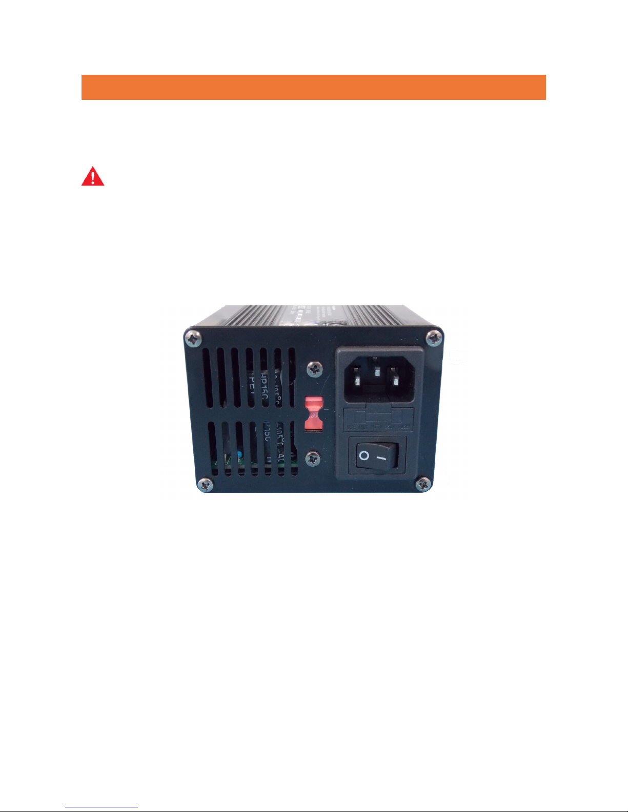
6.3.2 Charging
The battery charger supplied with the 8-port multiplexing box is shown in figure 5 below. Mains
voltage selector switch, and power On/Off switch, are located on the rear panel.
Figure 5: Battery charger connections
BARTINGTON INSTRUMENTS
DCN1040 Page 13 of 39 OM3100/2
WARNING: The charger mains voltage selector switch must be in the appropriate position,
i.e. either set to 230V or 125V. The internal battery must be charged with the supplied
charger only.
On the front of the charger there are two LEDS that will light up to indicate it is powered and
charging, see figure 6 below:
Figure 6: Battery Charger LED Indicators
Mains Indicator LED: Indicates mains power is on when RED.
Charge Indicator LED: Lights up when the charger cable is connected and powered. It will show
as RED during charging and GREEN when charging is complete.
WARNING: The charger must be switched off before connecting to and disconnecting from
the Grad-13 Multiplexer Box
Charge time from flat is approximately 8 hours.
Note: the Charge Complete LED turns green when the battery is around 95% charged;
allowing an extra hour or so after this point ensures a fully charged battery.
Refer to the Grad-13 product brochure for maximum ambient charging temperature.
For further information on connecting the charger to a mains supply, see Appendix A: Guidance
for Connection to Mains Supply.
Mains Indicator
Charge Indicator

BARTINGTON INSTRUMENTS
DCN1040 Page 14 of 39 OM3100/2
6.3.3 External Power
The unit can be powered by an external battery to be connected to the unit if the internal
batteries become exhausted. This is currently under development.
6.4.Fuses
For safety reasons, the battery (comprising four separate assemblies) has four internal fuses.
These are not customer replaceable and in the event of the fuses blowing, the device must be
returned to Bartington Instruments for repair.
7. Installation of the Grad-13
7.1. Unpacking
Safe handling precautions must be observed.
7.2. Orientation
The directions of the sensor axes are marked on the label at the connector end.
7.3. Mounting
The sensor assembly is mounted in a stress free manner within the outer protective tube.
Note: Ensure that the Grad-13 enclosure is not excessively stressed, as the alignment of
the sensors may be affected or the assembly integrity may be compromised allowing the
ingress of foreign matter.
Note: See drawings DR3344 and DR3286 on the product webpage.

BARTINGTON INSTRUMENTS
DCN1040 Page 15 of 39 OM3100/2
7.4. Connecting
The Grad-13 is connected to the Grad-13 battery box using the cable supplied. Connect power
supply to the mains adaptor panel socket located on the front of the unit using the cable
provided.
7.5. Connecting Custom Systems
A data protocol DP2629 can be provided if the Grad-13 is to be powered by and connected to a
custom system. Please contact Bartington Instruments for further information.
8.
Operating
I
ns
t
r
u
c
t
i
o
ns
8.1. Operation
During operation, ensure that the battery box and cables are kept away from the gradiometer
sensors.
Bartington Instruments supply a basic software, VisualGrad13, for communication with the Grad-
13.
If the user wishes to expand upon this or create their own software, this is simplified by using
the API which is documented in data protocol DP0105, available on request from Bartington
Instruments.
8.2. Visual Grad-13 Software Instructions
8.2.1. Installation
In order to connect the Grad-13 to a PC, an RS422 to USB/Ethernet converter is required. The
converter used and tested by Bartington instruments is the ‘Brainboxes’ RS422 converter, and
this will be refered to in this manual. However, there are many other commercially available
converters that can also be used.
The installation requires Brainboxes (or other) device drivers as well as the Bartington Grad-13
software. These need to be installed on a PC with a Windows OS.
Firstly install brainboxes USB to Serial software (driver for RS422 converter) before installing the
Grad 13 software.

BARTINGTON INSTRUMENTS
DCN1040 Page 16 of 39 OM3100/2
8.2.2. Installing the Brainboxes USB to Serial drivers
To install the Brainboxes USB to Serial drivers run the Brainboxes Setup.exe, without plugging in
the device. Accept all default options during installation.
The Grad 13 should then be plugged in (including the USB lead to Battery box). Plug the Grad-
13 into the Battery box and turn it on. The PC will then look for the correct device drivers for the
Grad 13. Allow the Brainboxes drivers to be installed for the plugged in device.
8.2.3. Installing the Grad13 Software
Note: Uninstall any existing versions of D660, Grad-13 or the Visual Grad-13 software via
the control panel before installing this software.
Run the Grad13Install.exe, andfollow the instructions. Once this has been completed it will
create three shortcuts on your desktop:
VisualGrad13 - Main Grad 13 Master Interface application.
DataPro - Data processor for data generated from the Grad13 Master application.
Grad13Logs - Shortcut to the Grad13 log file directory.
Note: The Visual Grad 13 Interface and Grad13 Data Processor application interfaces with
Microsoft’s Excel; if Excel is not installed on the PC then an error may appear when trying
to send data to Excel from Visual Grad 13 Interface and the Data Processor application. The
software can still be used without Excel installed.
8.2.4. Using the software
Open the Visual Grad-13 application (using the VisualGrad13 shortcut from the desktop), this will
display the Visual Grad-13 application as shown in Figure 7:

BARTINGTON INSTRUMENTS
DCN1040 Page 17 of 39 OM3100/2
Figure 7:Visual Grad-13 Software Main Window
8.2.4.1. Connecting to a Grad-13
Connect: The ‘Connect’ button is used to connect the software to the Grad13, the device
connection window shown in Figure 8 will then be displayed.
Note: the Grad 13 needs to be plugged in and powered before trying to connect.
Figure 8:The ‘Connect to a Grad-13’ Window
This window allows you to connect to a Grad-13 device, if the connection has already been
correctly configured. All connections that are currently available are listed in the drop down list
box at the top of the window. If this is blank, then you will need to configure a new connection.
Click ‘Connect’ to attempt to connect to the Grad-13 device using the selected connection.
Note: the Grad 13 may not be listed in the drop down list if it has not been plugged in
before selecting ‘Connect’ from the main window.

BARTINGTON INSTRUMENTS
DCN1040 Page 18 of 39 OM3100/2
Configure Connections
Before you can connect to a Grad-13 device, or if you wish to edit a connection, you need to use
the ‘Configure Connections’ option in the ‘Connect to a Grad-13’ window to set up your
connections. Clicking on this will display the window shown in Figure 9:
Figure 9:The ‘Manage Grad Connections’ Window
The ‘Edit’ button can be used to edit any existing connections that are listed. The ‘Remove’
button allows you to remove a preconfigured connection.
To create a new connection, click ‘Add’, this displays the window shown in Figure 10:
Figure 10:Adding a new connection

BARTINGTON INSTRUMENTS
DCN1040 Page 19 of 39 OM3100/2
This window allows you to specify:
The ‘Name’ of the connection, this appears in the drop down list when you attempt to connect to
a Grad-13 device.
The Node Address of the Grad-13 is set during manufacture and should be kept as 1 by default.
Whether the connection is a Serial Connection (i.e. USB to Serial) or an Ethernet connection.
Serial Settings
If connecting via serial connection, the correct COM Port should be selected (this is normally
the last one in the list). By default, only the Brainbox ports are listed (to which the Grad-13 is
connected), hence you may only see one COM port in the list.
The correct COM port can be identified by looking for the RS422/RS422 Serial Port (COM…) in
your PCs Device Manager under Ports (COM & LTP), see Figure 11 for an example.
Figure 11: Identifying the correct port using Device Manager
Baud Rate: The default baud rate is 115200.
Note: The Baud Rate has to be programmed in the Grad 13, therefore in most cases the
default rate should be used. The exception to this is when the Baud rate has been changed
by Bartington Instruments in order to output the full 200Hz bandwidth.
Ethernet Settings
Input the ‘IP Address’ and the ‘Port Number’ on the IP Address. (This will be printed on the
multiplexing box)
After configuring the settings and ensuring the Grad-13 device is powered on and connected,
you may test your settings by clicking ‘Test’. This will test the connection but will not leave the
connection open, and will disconnect from the Grad-13 upon completion. This test will display
either a success or failure message prompting you to check the configuration.
Clicking ‘Save’ will save the connection and the new name will then be listed in the Manage Grad
Connections window. The connection can then be selected in the drop down list shown in Figure
8.

BARTINGTON INSTRUMENTS
DCN1040 Page 20 of 39 OM3100/2
Successful Connection
When you successfully connect to your Grad-13 device, the Visual Grad-13 application window
options will change as shown in Figure 12:
Figure 12: Main window following successful connection to Grad-13
This window now gives the options to start a scan, display graphs or disconnect from the Grad-
13.
Note: Connections can fail if the Grad-13 device is not connected, connected to the wrong
connection, not powered, or incorrectly configured. This will lead to an error message
when attempting to connect.
8.2.4.2. Starting a scan
Once a Grad 13 is connected, a scan can be started. Scans are saved to .pct files in the Grad 13
Log directory (a shortcut to this is placed on the desktop by default during the installation). Scan
files are numbered sequentially, and created each time a scan is started.
Click ‘Start Scan’ to start a scan, as shown in Figure 13.
Figure 13: Start Scan
Other manuals for Grad-13 Series
1
This manual suits for next models
2
Table of contents
Other Bartington Measuring Instrument manuals

Bartington
Bartington Grad-13 Series User manual

Bartington
Bartington Mag613 User manual

Bartington
Bartington Mag-01 User manual

Bartington
Bartington MS2 User manual

Bartington
Bartington Grad601 User manual

Bartington
Bartington Mag690 User manual

Bartington
Bartington Mag-01 User manual

Bartington
Bartington Mag628 User manual

Bartington
Bartington Mag-01H User manual

Bartington
Bartington MS3 User manual


