SECTION 1
GENERAL
INFORMATION
PURPOSE
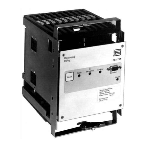
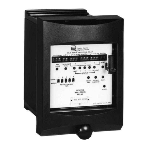
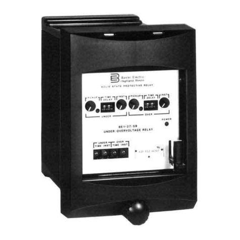
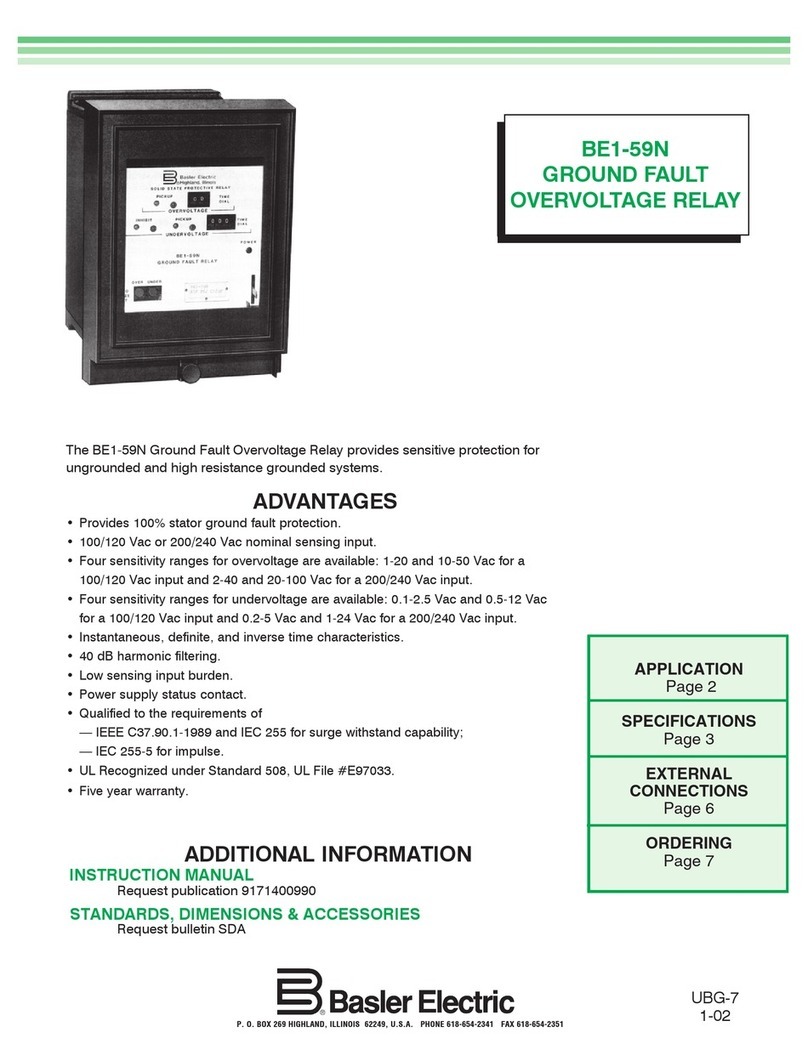
The
8E1-79
Multiple Shot Reclosing
Relay
is
a
solid-state
device
that
provides
automatic reclosure of
circuit
breakers
that
have
been
tripped
by
a protective
relay.
Because
many
power
circuit
faults
are temporary. the reclosing relay
can
be
programmed
to
make
up
to three attempts to
re-establish
service.
DESCRIPTION
The
Basler Multiple
Shot
Reclosing
Relay
senses opening
and
closing of
an
asso-
ciated
circuit
breaker.
When
the breaker opens, a
form
B auxiliary contact
on
the controlled
circuit
breaker
closes.
The
relay senses
this
contact closure
and.
after
a
programmed
interval
to
allow
any
arcing to
dissipate,
recloses the
breaker.
If
the
fault
still
exists
after
the breaker
has
been
reclosed, the
relay will
make
two
more
attempts
at
independently
programmable
intervals
.
If
the
fault
is
still
not
cleared,
and
the breaker
trips
a fourth time,
no
further
attempts will
be
made
to automatically reclose the breaker.
Programming
of the individual reclosing
intervals
is
available with
either
defi-
nite time delay steps or continuously adjustable
intervals.
With
the
definite
time option, the reclosing delay
intervals
are individually selected
on
three
front
panel
switches .
Each
switch
has
five pOSitions
and
covers a range
from
0.2
to
60
seconds.
With
the continuous time option, the reclosing delay
inter-
vals are individually
set
with three
front
panel controls
and
associated range
toggle switches.
Each
control (together with
it
s range switch) provides a con-
tinuous adjustment
from
0.2
to
60
seconds.
Adisable function
is
provided in the reclosing relay to
inhibit
automatic
reclosing.
When
an
external contact connected to the
relay's
disable input
;s
closed, the relay ignores
any
breaker tripping action
and
no
automatic reclosing
is
attempted.
Options are available:
(1)
To
provide
either
isolated
or non-isolated contact sensing;
(2)
To
limit
the
number
of reclosure attempts;
(3)
To
enable instantaneous breaker
tripping
for
any
trip;
(4) To
initiate
a
remote
alarm
when
a reclosure attempt
is
unsuccessful (the breaker
does
not close within a
set
time
limit);
and
(5)
To
reset
the relay
when
a rec10sure
is
not followed
by
a
trip
after
a
programmed
interval.
The
relay assembly
is
mounted
in a drawout cradle
and
enclosed in a standard,
utility
style
case available with
either
semi-flush or projection mounting.
Circuit
components
are accessible
by
removal
of t
he
individual printed
circuit
boards
from
the relay
cradle,
and
by
using
an
extender board (Basler
part
number
9112930
101) to
test
or
troubleshoot.
1-1
