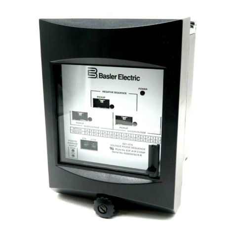
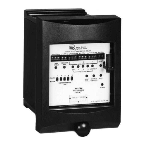
Basler BE1-67N User manual

INSTRUCTION MANUAL
FOR
GROUND DIRECTIONAL
OVERCURRENT RELAY
BE1-67N
Publication: 9190700990
Revision: F 08/07


9190700990 Rev F BE1-67N Introduction i
INTRODUCTION
This instruction manual provides information about the operation and installation of the BE1-67N Ground
Directional Overcurrent Relay. To accomplish this, the following information is provided:
•General Information and Specifications
•Controls and Indicators
•Functional Description
•Installation
•Testing
WARNING!
To avoid personal injury or equipment damage, only qualified personnel should
perform the procedures in this manual.
NOTE
Be sure that the relay is hard-wired to earth ground with no smaller than 12 AWG
copper wire attached to the ground terminal on the rear of the unit case. When
the relay is configured in a system with other devices, it is recommended to use a
separate lead to the ground bus from each unit.

ii BE1-67N Introduction 9190700990 Rev F
First Printing: May 1992
Printed in USA
© 1992-1993, 2005-2007 Basler Electric, Highland Illinois 62249 USA
All Rights Reserved
August 2007
It is not the intention of this manual to cover all details and variations in equipment, nor does this manual
provide data for every possible contingency regarding installation or operation. The availability and design
of all features and options are subject to modification without notice. Should further information be
required, contact Basler Electric.
BASLER ELECTRIC
ROUTE 143, BOX 269
HIGHLAND IL 62249 USA
PHONE +1 618.654.2341 FAX +1 618.654.2351
CONFIDENTIAL INFORMATION
of Basler Electric, Highland Illinois, USA. It is loaned for confidential use, subject
to return on request, and with the mutual understanding that it will not be used in
any manner detrimental to the interest of Basler Electric.

9190700990 Rev F BE1-67N Introduction iii
REVISION HISTORY
The following information provides a historical summary of the changes made to the BE1-67N instruction
manual (9190700990). Revisions are listed in reverse chronological order.
Manual
Revision and Date Change
F, 08/07 •Moved content of Section 6, Maintenance to Section 4.
•Updated power supply burden data in Section 1.
•Updated Target Indicator description in Section 3.
E, 01/07 •Enhanced the readability of various figures throughout the manual.
D, 10/06 •Updated description of Polarizing Source Select Switch (S3) in Table
2-2 of Section 2, Controls and Indicators.
•Updated Output Contacts ratings in Section 1, General Information.
C, 10/05 •Deleted references to service manual 9190700620.
•Removed reference to jumper-selectable Y power supply from style
chart. Updated power supply ratings in Section 1.
•Corrected instantaneous overcurrent maximum operating times listed
in the specifications and Table 3-5.
•Corrected the polarizing voltage input burden listed in the
specifications.
•Removed the shorting bar shown across terminals 5 and 6 in Figures
4-1 and 4-7.
•Corrected the current values listed in Table 3-2, Sensing Input
Ranges and Settings for 1 Aac Secondary.
•Updated all illustrations showing relay front panel or case cover.
•Created new Section 5 containing operational test procedures.
•Created new Appendix A containing characteristic curves previously
contained in Section 1.
•Created new Appendix B, Polar Graph Forms.
•Updated style/format of the manual.
B, 06/93 •Changed all sections of the manual to reflect revised specifications.
•Expanded switch and control terminology in Section 2.
•Revised Figure 3-1.
•In Section 4, included Iopolarization testing and a separate
operational test procedure for sensing input ranges 3 and 4.
A, 10/92 •Revised Figures 3-1 through 3-3 and added Figure 3-4.
•Added Section 6, Manual Change Information.
—, 05/92 •Initial release

iv BE1-67N Introduction 9190700990 Rev F
This page intentionally left blank.

9190700990 Rev F BE1-67N Introduction v
CONTENTS
SECTION 1 •GENERAL INFORMATION ................................................................................................ 1-1
SECTION 2 •CONTROLS AND INDICATORS........................................................................................ 2-1
SECTION 3 •FUNCTIONAL DESCRIPTION........................................................................................... 3-1
SECTION 4 •INSTALLATION .................................................................................................................. 4-1
SECTION 5 •TESTING ............................................................................................................................ 5-1
APPENDIX A •CHARACTERISTIC CURVES..........................................................................................A-1
APPENDIX B •POLAR GRAPH FORMS.................................................................................................B-1

vi BE1-67N Introduction 9190700990 Rev F
This page intentionally left blank.

9190700990 Rev F BE1-67N General Information i
SECTION 1 •GENERAL INFORMATION
TABLE OF CONTENTS
SECTION 1 •GENERAL INFORMATION ................................................................................................1-1
PURPOSE..............................................................................................................................................1-1
APPLICATION .......................................................................................................................................1-1
Zero Sequence Current......................................................................................................................1-1
Zero Sequence Voltage......................................................................................................................1-2
Dual Zero Sequence Current and Voltage.........................................................................................1-2
OUTPUT CONTACTS ...........................................................................................................................1-2
Relay Status Alarm.............................................................................................................................1-2
Tripping...............................................................................................................................................1-2
Auxiliary..............................................................................................................................................1-3
PUSH-TO-ENERGIZE OUTPUTS.........................................................................................................1-3
TARGETS..............................................................................................................................................1-3
POWER SUPPLY OPTIONS.................................................................................................................1-3
POWER-UP DELAY ..............................................................................................................................1-3
MODEL AND STYLE NUMBER.............................................................................................................1-3
Style Number Example.......................................................................................................................1-3
SPECIFICATIONS.................................................................................................................................1-4
Current Sensing (IO) Inputs ................................................................................................................1-4
Frequency...........................................................................................................................................1-4
Polarizing Current (I0).........................................................................................................................1-5
Polarizing Voltage (V0) .......................................................................................................................1-5
Directional Unit...................................................................................................................................1-5
Time Overcurrent ...............................................................................................................................1-5
Instantaneous Overcurrent.................................................................................................................1-6
Power Supply .....................................................................................................................................1-6
Output Contacts .................................................................................................................................1-6
Target Indicator ..................................................................................................................................1-7
Type Tests..........................................................................................................................................1-7
Agency Recognition ...........................................................................................................................1-7
Physical..............................................................................................................................................1-7
Figures
Figure 1-1. Zero Sequence Polarizing (Two-Winding Transformer) ......................................................... 1-1
Figure 1-2. Zero Sequence Polarizing (Three-Winding Transformer).......................................................1-2
Figure 1-3. Style Number Identification Chart...........................................................................................1-4
Tables
Table 1-1. Maximum Operate Times.........................................................................................................1-6
Table 1-2. Power Supply Types and Ratings............................................................................................1-6
ii BE1-67N General Information 9190700990 Rev F
This page intentionally left blank.

9190700990 Rev F BE1-67N General Information 1-1
SECTION 1 •GENERAL INFORMATION
PURPOSE
BE1-67N Ground Directional Overcurrent Relays provide ground fault protection for transmission and
distribution lines by sensing the flow of ground (zero sequence) current into or out of protected zones.
Zero sequence quantities provide a secure reference for the directional element because these quantities
are defined by the total source impedance of the power system.
APPLICATION
BE1-67N Ground Directional Overcurrent Relays are recommended for multi-grounded systems to
provide coordination necessary to selectively trip the faulted line. A directional overcurrent relay operates
by comparing the measured current to a reference quantity to determine whether current is flowing into or
out of the protected zone. Reference quantity is also referred to as polarizing quantity.
BE1-67N relays use one of the following quantities for polarization:
•Zero sequence current
•Zero sequence voltage
•Dual zero sequence current and voltage
The polarizing quantity is field selectable using a switch mounted on the analog circuit board. When the
selected polarizing quantities are less than the minimum threshold, relay operation will be inhibited. When
using dual polarization, the relay will operate if either polarizing quantity is above minimum threshold.
Zero Sequence Current
Zero sequence current polarization is preferred for applications with low ground source impedance.
Figure 1-1 illustrates relay connections that obtain zero sequence current (3I0) from a separate current
transformer in the grounded neutral of a two winding wye-delta power transformer. Figure 1-2 illustrates
relay connections that obtain zero sequence current from a current transformer(s) in the grounded
neutral(s) of a three winding transformer. The magnitude of the zero sequence current used for polarizing
may be different from that of the ground current seen by the measuring element(s) of the relay.
Figure 1-1. Zero Sequence Polarizing (Two-Winding Transformer)

1-2 BE1-67N General Information 9190700990 Rev F
Figure 1-2. Zero Sequence Polarizing (Three-Winding Transformer)
Zero Sequence Voltage
Zero sequence voltage polarization is preferred for higher ground source impedances. Refer to Figures 1-
1 and 1-2 for relay connections that obtain zero sequence voltage (3V0) from a set of grounded wye-
broken delta voltage transformers. The voltage polarized relay has a directional polarization adjustment to
match the impedance angle of the protected line to the characteristic angle of the relay. This is the angle
about which the directional angle is centered. A choice of line angles allows the relay to be adjusted to
include the resistance component of the ground fault.
Dual Zero Sequence Current and Voltage
Dual polarization is preferred where ground source impedance varies, or to provide redundant
polarization. Dual polarization is achieved using a polarizing signal that is the phasor sum of the current
and voltage polarizing signals.
OUTPUT CONTACTS
BE1-67N relays have the following output contacts: relay status alarm (relay fail), tripping, and auxiliary
(optional).
Relay Status Alarm
A relay status alarm output contact (relay fail) indicates that proper voltages are not being supplied to the
internal relay circuitry or that the microprocessor self-diagnostics has detected an error. This alarm output
contact is normally closed.
Tripping
Normally open or normally closed tripping contacts are included for each function within the relay.
Configuration of these contacts is defined by the relay style number. These output contacts are used with
optionally selected target indicator circuits.

9190700990 Rev F BE1-67N General Information 1-3
Auxiliary
Normally open, normally closed, or single pole double throw (SPDT) auxiliary contact configurations are
provided to act in parallel with the tripping function(s) of the relay. Configuration of the auxiliary output
contacts are also defined by the relay style chart.
An auxiliary contact can be configured (via internal switches) to operate in parallel with any combination
of tripping outputs. Configurable auxiliary outputs permit use of the BE1-67N relay in various carrier
schemes.
PUSH-TO-ENERGIZE OUTPUTS
A push-to-energize pushbutton is included for each tripping output contact. These pushbuttons can be
used to verify correct operation of external control circuit wiring without the need to supply test signals to
the relay. Control power must be applied for this function to operate. The pushbuttons are recessed
behind the relay front panel and are not accessible with the cover installed.
TARGETS
One target is included for each tripping function as specified by style number. Targets are operated either
by the internal signal initiating tripping (internally operated) or by a minimum of 200 mAdc flowing through
the series circuit consisting of the target coil and output relay contacts (current operated). Within a
specific relay, all targets must be operated in the same way.
POWER SUPPLY OPTIONS
Various power supply options are available to allow the BE1-67N relay to be used with standard supply
voltages. See the style chart for details.
POWER-UP DELAY
A power-up delay timer is initiated upon application of control power to the relay to prevent undesired
contact transitions when sensing signals are present. Operation of measuring circuits and output circuits
are inhibited (less than 0.5 seconds) until the power-up delay period has expired.
MODEL AND STYLE NUMBER
Electrical characteristics and operational features included in a specific relay are defined by a
combination of letters and numbers that makes up the style number. Figure 1-3 illustrates the BE1-67N
style number identification chart. The style number together with the model number describe the features
and options in a particular device and appear on the front panel, draw-out cradle, and inside the case
assembly.
Style Number Example
Operating features and characteristics of BE1-67N relays are identified by the style number. For example,
a BE1-67N relay with style number A1E-Z2J-B4C0F has the following features and options.
Azero sequence current, voltage, or dual polarized
160 Hz sensing with a range of 0.25 to 6.0 Aac
Enormally open output contacts
Z2 switch-selectable timing characteristics
Jrelay operating power derived from 125 Vdc or 120 Vac
Bcurrent operated targets
4two instantaneous elements: directional and non-directional
Cpush-to-energize outputs (pushbuttons)
0no auxiliary output contacts
Fsemi-flush case mounting

1-4 BE1-67N General Information 9190700990 Rev F
4
Figure 1-3. Style Number Identification Chart
SPECIFICATIONS
BE1-67N relays have the following features and capabilities.
Current Sensing (IO) Inputs
Pickup Adjustment Range
Range 1 and 2: 0.25 to 6.0 Aac
Range 3 and 4: 0.05 to 1.2 Aac
Current Rating
Sensing Input Range 1 and 2
Continuous Rating: 7.5 Aac
5 Minute Rating: 20 Aac
1 Second Rating: 150 Aac
Sensing Input Range 3 and 4
Continuous Rating: 1.5 Aac
5 Minute Rating: 4 Aac
1 Second Rating: 30 Aac
Burden
Maximum: <0.1 Ω
Frequency
Nominal
50 Hz or 60 Hz

9190700990 Rev F BE1-67N General Information 1-5
Range
50 Hz Nominal: 45 to 55 Hz
60 Hz Nominal: 55 to 65 Hz
Polarizing Current (I0)
Current Rating
Continuous: 10 Aac
1 Second: 150 Aac
Minimum Sensing Level
Directional Instantaneous: Front-panel adjustable from 0.75 to 2.0 Aac
Time Overcurrent: Fixed at 0.2 Aac
Burden
Maximum: <0.1 Ω
Polarizing Voltage (V0)
Maximum Rating (Line-to-Neutral)
Continuous: 240 Vac
1 Second: 360 Vac
Minimum Sensing Level
Directional Instantaneous: 4.0 Vac
Time Overcurrent: 0.75 Vac
Burden
At 120 Vac: <1 VA
Operating Region
Operating region is ±75°(150°window) centered about the characteristic angle.
Harmonic Sensitivity
Polarizing voltage is not affected by third or higher harmonics.
Characteristic Angle
Characteristic angle is switch-selectable to 0 or 60°. Characteristic angle accuracy is ±5°for V0inputs
below 30 Vac and ±10°for V0inputs greater than 30 Vac.
Directional Closing Band
Directional closing band is ±75°centered about the characteristic angle.
Directional Unit
Response Time: Within 15 ms to change in direction and magnitude
Repeatability: Set angles are repeatable within ±3% or 1°, whichever is greater
Time Overcurrent
Pickup Range
Sensing Input Range 1 and 2: 0.25 to 6 Aac
Sensing Input Range 3 and 4: 0.05 to 1.2 Aac
Pickup Accuracy
Within ±5% of the expected value established by tap selector switch with the intertap adjustment at its
maximum clockwise setting.
Repeatability
Repeatability of pickup setting (combination of tap selector switch and intertap adjustment) is ±2%.
Response Time Accuracy
Within ±5% of the time value indicated on the characteristic time curve or 25 ms, whichever is greater.

1-6 BE1-67N General Information 9190700990 Rev F
Operate Time Repeatability
Operate time is repeatable within ±2% or 25 ms, whichever is greater.
Instantaneous Overcurrent
Pickup Range for Directional and Non-Directional Instantaneous Elements
Sensing Input Range 1 and 2: 2 to 100 Aac
Sensing Input Range 3 and 4: 0.4 to 20 Aac
Maximum Operate Time
Maximum operating times are derived while
stepping from a steady state (normal conditions)
to an overcurrent condition. When stepping from
an inhibit state, the maximum times are longer.
Table 1-1 lists the instantaneous operate times
for multiples of pickup.
Table 1-1. Maximum Operate Times
Multiple of Pickup Operate Time
1.05 Aac 100 ms
2.0 Aac 35 ms
5.0 Aac 20 ms
Pickup Accuracy: Within ±5% of the defined pickup setting
Repeatability: ±5%
Response Time: Within 25 ms to a current reversal after fault inception
Power Supply
Relay operating power may be obtained from a wide variety of external sources. When ordering, any one
of five internal power supply types may be selected to match the operating power voltage level available
at your site. Available power supply types are listed in Table 1-2.
Table 1-2. Power Supply Types and Ratings
Input Voltage
Type Nominal Range Burden at Nominal
J (mid range) 125 Vdc
120 Vac 24 to 150 Vdc
90 to 132 Vac 2.9 W
12.8 VA
K (mid range) 48 Vdc 24 to 150 Vdc 2.7 W
L (low range) 24 Vdc 12 to 32 Vdc ∗2.8 W
Y (mid range) 48 Vdc
125 Vdc 24 to 150 Vdc
24 to 150 Vdc 2.7 W
2.9 W
Z (high range) 250 Vdc
240 Vac 68 to 280 Vdc
90 to 270 Vac 3.1 W
22.0 VA
∗Type L power supply may require 14 Vdc to begin operation. Once operating, the voltage may be
reduced to 12 Vdc.
Output Contacts
Resistive Ratings
120 Vac: Make, break, and carry 7 Aac continuously
250 Vdc: Make and carry 30 Adc for 0.2 s, carry 7 Adc continuously, and
break 0.3 Adc
500 Vdc: Make and carry 15 Adc for 0.2 s, carry 7 Adc continuously, and
break 0.3 Adc
Inductive Ratings
120 Vac, 125 Vdc, 250 Vdc: Break 0.3 A (L/R = 0.04)

9190700990 Rev F BE1-67N General Information 1-7
Target Indicator
A choice of either internally operated targets or current operated targets is available as specified by style
number. Internally operated targets use the internal trip signal to energize the output relay and target
drivers. Current operated targets are energized by a minimum of 0.2 A flowing through the output
contacts.
Type Tests
Dielectric Strength
Withstands 1,500 Vac at 60 Hz for 1 minute in accordance with IEC 255-5 and ANSI/IEEE C37.90.1-1989
Surge Withstand Capability
Qualified to C37.90.1-1989 and IEC 255-5
Radio Frequency Interference
Field-tested using a 5 W, handheld transceiver operating at random frequencies centered around 144
MHz and 440 MHz, with the antenna located 6 inches (150 mm) from the relay in both horizontal and
vertical planes.
Shock
Withstands 15 G in each of three mutually perpendicular planes without structural damage or degradation
of performance.
Vibration
Withstands 2 G in each of three mutually perpendicular planes, swept over the rang of 10 to 500 Hz for a
total of 6 sweeps, 15 minutes each sweep, without structural damage or degradation of performance.
Agency Recognition
UL
UL recognized per standard 508, UL file number E97033.
GOST-R
Gost-R certified No. POCC US.Me05.B03391; complies with the relevant standards of Gosstandart of
Russia. Issued by accredited certification body POCC RU.0001.11ME05.
Physical
Temperature
Operating: –40 to 70°C (–40 to 158°F)
Storage: –65 to 90°C (–85 to 194°F)
Dimensions
See Section 4, Installation.
Weight
Maximum: 18 lb (8.2 kg)

1-8 BE1-67N General Information 9190700990 Rev F
This page intentionally left blank.

9190700990 Rev F BE1-67N Controls and Indicators i
SECTION 2 •CONTROLS AND INDICATORS
TABLE OF CONTENTS
SECTION 2 •CONTROLS AND INDICATORS........................................................................................2-1
INTRODUCTION....................................................................................................................................2-1
FRONT PANEL CONTROLS AND INDICATORS.................................................................................2-1
ANALOG AND DIGITAL CIRCUIT BOARD CONTROLS......................................................................2-3
MOTHER CIRCUIT BOARD CONTROLS.............................................................................................2-4
Figures
Figure 2-1. Front Panel Controls and Indicators .......................................................................................2-1
Figure 2-2. Analog and Digital Circuit Board Controls...............................................................................2-3
Figure 2-3. Auxiliary Relay Select Switch Location...................................................................................2-4
Tables
Table 2-1. Front Panel Controls and Indicators......................................................................................... 2-2
Table 2-2. Analog and Digital Circuit Board Controls................................................................................2-3
Table 2-3. Auxiliary Relay Select Switch Selections.................................................................................2-4

ii BE1-67N Controls and Indicators 9190700990 Rev F
This page intentionally left blank.
Other manuals for BE1-67N
1
Table of contents
Other Basler Relay manuals

Basler
Basler BE1-81O/U User manual

Basler
Basler BE1-25/79TR User manual

Basler
Basler BE1-50/51B-237 User manual

Basler
Basler BE1-50/51B-232 User manual

Basler
Basler BE1-51C User manual

Basler
Basler BE-51/27C User manual

Basler
Basler BE1-50/51B-214 User manual

Basler
Basler BE1-27 User manual

Basler
Basler H12345678 R U User manual

Basler
Basler BE1-51/27R User manual

Basler
Basler BE1-81 User manual

Basler
Basler BE1-51 User manual

Basler
Basler BE1-32R User manual

Basler
Basler BE1-11g User manual

Basler
Basler BE1-51/27R User manual

Basler
Basler BE1-59N User manual

Basler
Basler BE1-50BF User manual

Basler
Basler BE1-49 User manual

Basler
Basler BE1-87G User manual

Basler
Basler BE3-GPR User manual