Baso 120-2 User manual
RED
WHITE
RED A-GREEN
BLACK
BLACK
SD
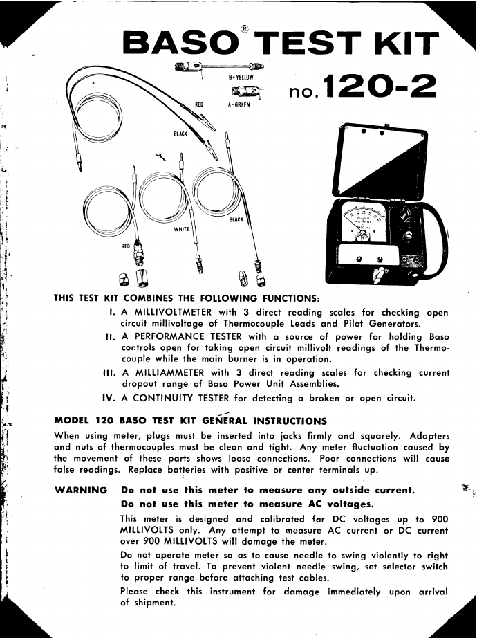
THIS TEST KIT COMBINES THE FOLLOWING FUNCTIONS:
A MILLIVOITMETER with 3 direct reading scales for checking open
circuit millivoltage of Thermocouple Leads and Pilot Generators.
A PERFORMANCE TESTER with a source of power for holding Baso
controls open for taking open circuit millivolt readings of the Thermo-
couple while the main burner is in operation.
A MILLIAMMETER with 3 direct reading scales for checking current
dropout range of Baso Power Unit Assemblies.
A CONTINUITY TESTER for detecting a broken or open circuit.
MODEL 120 BASO TEST KIT GENERAL INSTRUCTIONS
When using meter, plugs must be inserted into jacks firmly and squarely. Adapters
and nuts of thermocouples must be clean and tight. Any meter fluctuation caused by
the movement of these parts shows loose connections. Poor connections will cause
false readings. Replace batteries with positive or center terminals up.
WARNING Do not use this meter to measure any outside current.
Do not use this meter to measure AC voltages.
This meter is designed and calibrated far DC voltages up to 900
MILLIVOLTS only. Any attempt to measure AC current or DC current
over 900 MILLIVOLTS will damage the meter.
Do not operate meter so as to cause needle to swing violently to right
to limit of travel. To prevent violent needle swing, set selector switch
to proper range before attaching test cables.
Please check this instrument for damage immediately upon arrival
of shipment.
.12O-2
BASOiiB-YEL[OW

I. Procedure for taking open circuit MILLIVOLT READINGS of the Thermocouple.
Disconnect Thermocouple from Baso Control and attach proper cable to
Thermocouple.
Turn selector switch to the MV range scale needed for the type of Thermocouple
being tested. Pilot Generators are tested on the 300 or 900 MV scale, as
needed. Insert plug end of cable in millivolts jack of test kit.
Millivolt readings should agree with those given in Table I, with a normal
pilot flame.
II. Procedure for taking fixed load millivolt readings of the thermocouple.
Note:
CABLES AND
THERMOCOUPLE
ADAPTERS FOR
MILLIVOLT
TESTING
Red
Red
THERMOCOUPLE LEAD
A-GREEN
Black
TRANSFORMER
Lc
PtLOT BURNER GAS LINE
Fits series 17 and 50 Thermocouples.
With Adapter 1, Fits 80 Series Thermocouples.
With Adapter 2, Fits B30 and B20 Series Thermbcouples.
With Adapter 4, Fits 97 and 107 Series Thermocouples.
Fits other makes of Thermocouples or Pilot Generators
and Basofron valves.
- Fixed Load Adapter
- Closed Circuit Adapter
2
Disconnect thermocouple from Baso control and attach fixed load adapter A
to thermocouple using proper fitting.
Attach alligator clip cable to terminals of fixed load adapter A. Bent
terminal indicates negative polarity.
Turn selector switch to MV range scale needed for the type of therrnocoupJe
being tested. Insert plug end of clip cable in millivolts jack of test kit.
Millivolt readings should agree with those given in Table I, with a normal
pilot flame.
Procedure Iand Procedure II are to be used for testing Baso Thermocouple
Leads and Procedure IV for drop-out testing of Baso Power Units.
Do not use the closed circuit adapter for testing Baso Automatic
Pilot Control Systems.
POWER SOJRCE I HE RMOS IA
bent terminal

III. Procedure for PERFORMANCE TESTING.
Attach proper cables to Thermocouple Lead and Baso Power Unit.
Loosen thermostat or control wire from transformer, or shut off manual cock
in gas line.
With the selector switch turned to the proper milliamp range, turn the adjuster
knob to get a full scale reading, and reset the Baso control. Caution: The
control will now remain open for further tests until the power unit connection
is broken or until the milliamp jack is removed from test kit.
Turn the selector switch to the proper millivolt scale and take a reading with
the main burner off.
Connect loosened control wire, or turn on manual valve to bring main burner
on. Observe millivolt readings throughout normal cycle of operation, watching
for millivolt decreases due to operational conditions.
CABLES FOR
PERFORMANCE
TESTING
Use Proper
Millivolt
Test & Dropout
Test Cables
ABLE I. THERMOCOUPLE
LEAD TYPE
OUTPU.
TURN DOWN
urtr LIKI..UII
MV RANGE Minimum Voltage
Using Adapter "A's
NORMAL NOT LESS THAN
17D 4 MV 30-35 16 12
B20 5 MV 25-35 17 9
B30 30 MV 115-135 100 30
50,58D 4 MV 17-20 11 9
80, 88D 4 MV 20-25 15 9
87D 4 MV 30-35 17 9
88E, 88H with H Pilot 4 MV 14-17 12 7
88E 4 MV 25-30 17 9
97D 4 MV 30-35 21 13
107D 4 MV 30-35 21 13
in Combination For all 800, 300, 500 Baso Controls, Basoid, Actrol, or Basotrol,
Automatic Pilot installations.
light pilot burner
In the turn-down test, the pilot flame is reduced to the point that
the TC open-circuit output is at the turn-down level. The pilot must
be able to light the main burner within 4 seconds in this condition.
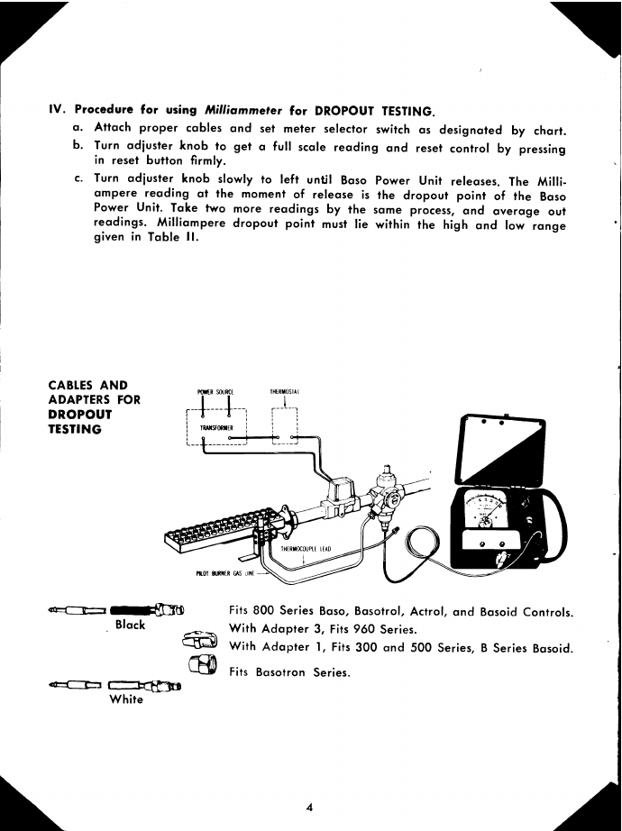
IV. Procedure for using Milliammeter for DROPOUT TESTING.
Attach proper cables and set meter selector switch as designated by chart.
Turn adjuster knob to get a full scale reading and reset control by pressing
in reset button firmly.
Turn adjuster knob slowly to left until Baso Power Unit releases. The Mliii-
ampere reading at the moment of release is the dropout point of the Baso
Power Unit. Take two more readings by the same process, and average out
readings. Milliampere dropout point must lie within the high and low range
given in Table II.
CABLES AND
ADAPTERS FOR
DROPOUT
TESTING
Black
White
Fits 800 Series Baso, Basotrol, Actrol, and Basoid Controls.
With Adapter 3, Fits 960 Series.
With Adapter 1, Fits 300 and 500 Series, B Series Basoid.
Fits Basotron Series.
4

5
BASO MODEL SET
SWITCH MA RANGE OF
POWER UNIT ASSY. E0LE TYP
TH AND E
All 300 and 500 Series
Baso Valves and
B Series Basoid Valves
900MA 250 600 No. 50 or No. 58 Up
to 54" mcI. No. 17D
55" to 72" md.
X3* Power Units for 300
and 500 Series Baso Valves
and B Series Basoid Valves
900 and
300MA
180 315 No. 17D
73" to 144" mcI.
X4" Power Units for 300
and 500 Series Baso Valves
and B Series Basoid Valves
300MA 110 220 No. 17D
145" to 240" mcI.
808, A809, 811, t815,
A817F, t818, 819, 820,
821, 825, A828, 829,
Any 830, 831, t832, D833,
Any 840, 841, Any 842,
t843, 845, 846, 850, 852,
853, 1815, 1825
854, 856, 8815, B1815, 8844,
GAV, GHV, GKV, GRV, GSV,
GTV, GXV, NDV
Basoid Valve AF, AG, AJ,
AK, Al-I
Basoid Valve AF, AG, AJ, AK
Basstat Valve CA
Basotrol Valve GFV, NBV, NCV
Actrol Valve MAS, MCS, MCV,
MCVR
300MA 100 300 No. 80 or No. 88
Up to 54" mcI.
No. 87
55" to 72" mcI.
W850, W853 300MA 20 50 No. B2OD
24" to 60" mcI.
X5* Power Units for
above Baso Valves 300MA 60 200 No. 87
73" to 144" mcI.
X6* Power Units for
above Baso Valves 300MA 50 145 No. 87
145" to 240" md.
TABLE II. DROPOUT RANGE
For Baso Controls or their Power Units
Controls ore in satisfactory condition if the point of dropout falls within the specified
range
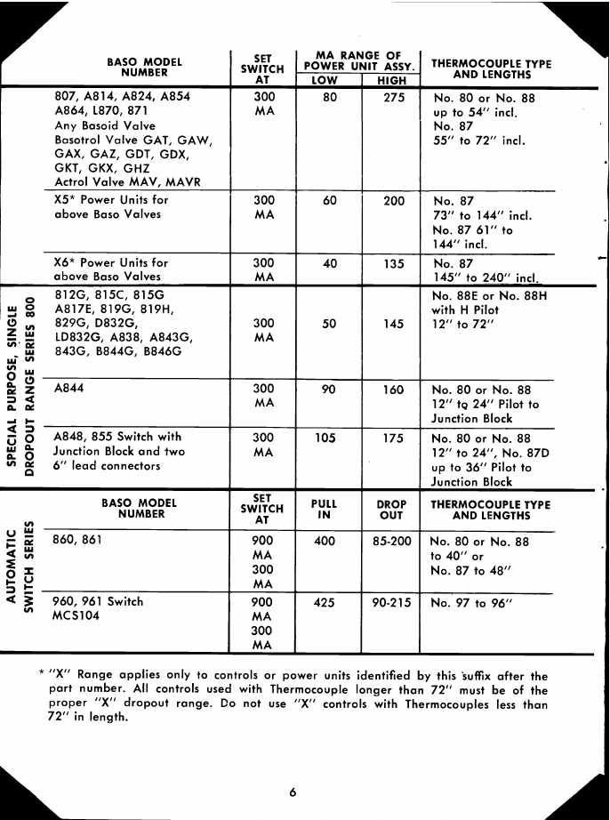
* "X" Range applies anly to controls or power units identified by this suffix after the
part number. All controls used with Thermocouple longer than 72" must be of the
proper "X" dropout range. Do not use "X' controls with Thermocouples less than
72" in length.
6
VBASO MODEL
NUMBER SET
SWITCH
AT
MA RANGE OF
POWER UNIT ASSY. THERMOCOUPLE TYPE
AND LENGTHS
LOW HIGH
807, A814, A824, A854
A864, 1870, 871
Any Basoid Valve
Basotral Valve GAl, GAW,
GAX, GAZ, GDT, GDX,
GKT, GKX, GHZ
Actrol Valve MAY, MAVR
300MA 80 275 No. 80 or Na. 88
up to 54" mcI.
No. 87
55" to 72" mcI.
X5* Power Units for
above Baso Valves 300MA 60 200 No. 87
73" to 144" mcI.
No. 87 61" to
144" mcI.
X6* Power Units for
above Baso Valves 300MA 40 135 No. 87
145" to 240" mcI.
812G. 815C, 815G
A817E, 819G, 819H,
0829G, D832G,
1D832Q, A838, A843G,
ui 843G. B844G, B846G
300MA 50 145
No. 88E or No. 88H
with H Pilot
12" to 72"
A844
Q.
300MA 90 160 No. 80 or No. 88
12" tg 24" Pilot to
Junction Black
A848, 855 Switch with
Junction Black and two
SI 6" lead connectors
300MA 105 175 No. 80 or No. 88
12" to 24", No. 87D
up to 36" Pilot to
Junction Block
BASO MODEL
NUMBER SET
SWITCH
AT PULLIN DROP
OUT THERMOCOUPLE TYPE
AND LENGTHS
860, 861 900MA300MA
400 85-200 No. 80 or No. 88
to4O"or
No. 87 to 48"
4960, 961 Switch
'MCS1O4 900MA300MA
425 90-215 No. 97 to 96"

Procedures for CONTINUITY TESTING.
Use proper cable and set selector switch to 300 MA scale.
With plug end of clip cable inserted in millivolt Jack, touch the alligator clips
together and turn the adjuster knob until you get a full scale (300 MA)
reading. If you are unable to get a full scale reading the connections are
poor or the batteries should be replaced.
Test for open circuit by touching or clamping the alligator clips to the terminal
or points in a circuit to be checked. DO NOT ATTEMPT THIS CHECK BEFORE
CUTTING OFF THE LINE POWER TO THE APPLIANCE.
If the circuit has very low resistance, you will get a full scale reading, but if a
coil or other resistance is in the circuit being tested this added resistance will
give a reading less than full scale. Any reading at all indicates a complete
circuit.
(Note: In effect this meter is being used as an ohmmeter when checking con-
tin u I ty.)
CABLE FOR
CONTINUITY
TESTING
R souc IHRMOAI
PIlOT BURMR GAS LIN( TRMOCOUE LEAD
Clip to Terminal Posts or Wire ends, or use as probes.
(Polarity not important for continuity testing.)
7
Plug into mA jack, not mV jack.
milliamp
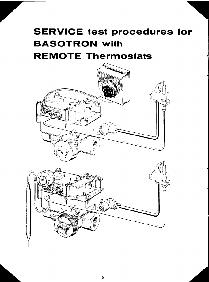
SERVICE test procedures for
BASOTRON with
REMOTE Thermostats

Poor MV output.
Excessive draft.
Recirculation of flue
products.
Excessive tempera.
ture.
Improper pilot flame
size or characteristic.
Defective thermocouple.
Weak holding BASO
power unit.
insufficient MV output.
Weak or defective ther.
mocou pie.
High resistance in con-
trol circuit.
Loose thermostat wiring
or defective thermostat.
Defective actuator.
Use Test Procedure lB.
Baffle secondary air or
shield pilot burner.
Check venting and main
burner orifice sizing and
correct where necessary.
Check main burner in-
put and correct if nec-
essary.
Check gas pressure,
clean pilot burner, and
adjust flame.
Test thermocouple under
Test Procedures Iand II
on page 2.
Test under Procedure lll.A.
Use Test Procedure lB.
(Check and correct as in
(a) through (d) above).
Use Test Procedure Iand
Replace thermocouple if
necessary.
Use Test Procedure Il-Ill.
Isolate source of resistance
and correct or replace as
indicated.
Use Test Procedure IV. Cor-
rect or replace as indicated.
Use Test Procedure lilB or
Replace if necessary.
A
CONDITION
Pilot burner outage or
varying performance.
Pilot burner burning, plug
valve knob turned to ON
position, thermostat call-
ing for heat. Main burner
does not come on.
Thermostat not calling for
heat, or turned way
down, plug valve knob
in ON position - main
burner will not shut off.
SERVICE SUGGESTIONS
POSSIBLE CAUSE
Shorted thermostat cir-
cuit.
Foreign particles lodged
between valve seat.
9
REMEDY
Check thermostat wires for
shorts.
Remove top of control and
clean valve seat.

10
BA SOT RON
ACTUATOR
BASO POWER UNIT
DIAGRAM I
- 030 DTN ER MOCOVPI.(
kTE5T KIT
7JUMPER
2
THERMOSTAT
White cable plugged into MA lack and attached to IC terminal post. Red cable plugged
into MV jack and attached with adapter 2 to IC. Jumper clip across thermostat
term in a Is.
PROCEDURE No. I (See Diagram I)
Isolated Open Circuit MV Test of Thermocouple
Step A. - With Main Burner Off
Turn plug valve to PILOT position.
Attach cables as shown.
Turn meter adjustment knob to right to full setting to provide holding power
for BASO unit, push reset and light the pilot burner, and allow time enough
for the thermocouple to reach its maximum reading.
AT THIS POINT THE NORMAL READING SHOULD BE 125 TO 150 MILLIVOLTS.
If the reading is less: Check thermocouple under procedure I and II on page 2.
Check the pilot under service suggestions (Page 9) for "Pilot outage" under (d).
Step B. - With Main Burner On
1. Cycle main burner on and off, simulating normal operating conditions, by
turning the red plug valve from PILOT to ON positions. IF MILLIVOLT READING
DROPS BELOW 85 MV AT ANY POINT DURING THE OPERATION OF THE
APPLIANCE, THE CAUSE OF THIS DROP SHOULD BE DETERMINED AND
CORRECTED. (See service suggestions under "Poor MV output" (a) thru (d).)
1
I
milliamps

)DIAGRAM II
_- B300THERUOCQIjPL(
THERMOSTAT
Thermostat wire disconnected from Terminal 1. Selector switch turned to 300 MV. Clip
cable plugged into MV jack. Red clip attached to Terminal 1. Black clip attached to
Terminal 2.
PROCEDURE No. II (See Diagram II)
Closed Circuit MV Test of Entire Circuit
Attach Millivoltmeter cable as shown.
Set thermostat to highest setting.
Turn plug valve knob to PILOT position, push down r&set button and Ight
pilot. Allow thermocouple to become fully heated, and note maximum reading.
AT THIS POINT, THE METER WILL INDICATE AN OPEN CIRCUIT MV READING
OF THE THERMOCOUPLE AS IN PROCEDURE IA.
Assuming the open circuit MV read-
ing is within range, touch the dis- OPEN CIRCUIT CLOSED CIRCUIT
connected thermostat wire to its MV READING MV READING
terminal. AT THIS POINT, THE
METER WILL INDICATE A CLOSED 150 45 or less
CIRCUIT READING, AND SHOULD 145 43½ or less
BE .3 OR LESS OF THE OPEN 140 42 or less
CIRCUIT READING AS TABULATED. 135 40½ or less
130 39 or less
If the closed circuit reading is 125 37½ or less
greater than indicated - 120 36 or less
Test the thermostat circuit under 115 341/2 or less
Procedure IV. 110 33 or less
Test the actuator under Procedure 105 31½ or less
IIIB. 100 30 or less
If both of these check out satis- 95 28½ or less
factorily, replacement of the 90 27 or less
thermocouple is indicated. 85 25½ or less
5. With thermostat wire connected, turn plug valve knob to ON to light main
burner. UNDER OPERATING CONDITIONS THIS READING SHOULD REMAIN
FAIRLY CONSTANT. A considerable decrease in millivoltage would indicate
adverse conditions in the combustion chamber affecting the pilot flame. Check
suggestions listed under PILOT BURNER OUTAGE.

I1
DIAGRAM III
Thermostat wires disconnected, or integral thermostat removed. Jumper clip across
thermostat terminals. White cable plugged into MA lack and attached to thermocouple
post. Selector switch set at 0-300 MA scale.
PROCEDURE No. III (See Diagram III) (For testing with a millivoltmeter
Isolated Test of Actuator and Safety Shutoff only, use Procedure V)
Step A. - BASO Safety Power Unit Test
Before attaching meter cables, set plug valve knob to PILOT position.
Attach proper cables as shown.
With plug valve in PILOT position, turn meter adjustment knob right to highest
reading position, push reset button and light the pilot. (The meter will hold
the BASO power unit open.)
Slowly turn meter adjustment knob to left until BASO power unit drops out,
shutting off the pilot flame. THIS SHOULD OCCUR BETWEEN 45 MA AND
90 MA. A dropout point higher than 90 MA indicates a weak holding unit and
requires replacement.
Step B. - Actuator Test - For Valves with Pilot Line Baso
With plug valve knob in PILOT position, turn meter adjustment knob to right
to highest setting.
Push reset button down and light pilot.
Turn plug valve knob to ON, lighting main burner.
Push down on reset button, holding it down while turning the meter adjustment
knob slowly to the left to the point where the main burner goes off, and to the
right to the point where the main burner comes on. THE CLOSING POINT
SHOULD BE AT 35 MA OR BELOW. THE OPENING POINT SHOULD BE AT
ANY POINT UP TO 110 MA. Repeat two or more times and take an average
reading. A higher opening or closing point indicates replacement.
Actuator Test - For Valves with Main Line Baso
Turn meter adjusting knob to the left as far as possible. Attach thermocouple
to Baso.
With plug valve knob in pilot position, push reset button down and light pilot.
Turn plug valve knob to on.
Turn meter adjusting knob slowly to the right until main burner comes on. The
point at which this occurs would be any point up to 110 MA. Turn meter
adjusting knob slowly to left until main burner goes off. (If adjustment does
not reduce low enough, remove plug from Test Kit jack to accomplish closing.)
Any closing point below 35 MA is satisfactory.
13
BASO POWER UNIT
BA SOT RON
ACTUATOR
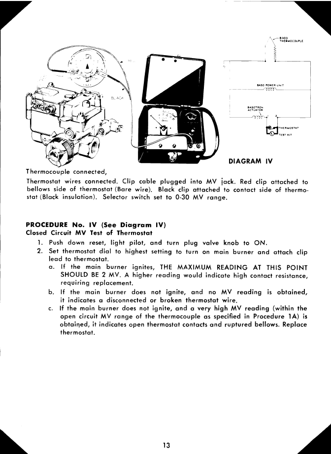
DIAGRAM IV
_- B300THERMOCOUPLE
THERMOSTAT
TEST RIT
Thermocouple connected,
Thermostat wires connected. Clip cable plugged into MV jack. Red clip attached to
bellows side of thermostat (Bare wire). Black clip attached to contact side of thermo-
stat (Black insulation). Selector switch set to 0-30 MV range.
PROCEDURE No. IV (See Diagram IV)
Closed Circuit MV Test of Thermostat
Push down reset, light pilot, and turn plug valve knob to ON.
Set thermostat dial to highest setting to turn on main burner and attach clip
lead to thermostat.
If the main burner ignites, THE MAXIMUM READING AT THIS POINT
SHOULD BE 2 MV. A higher reading would indicate high contact resistance,
requiring replacement.
If the main burner does not ignite, and no MV reading is obtained,
it indicates a disconnected or broken thermostat wire.
If the main burner does not ignite, and a very high MV reading (within the
open circuit MV range of the thermocouple as specified in Procedure 1A) is
obtained, it indicates open thermostat contacts and ruptured bellows. Replace
thermostat.
BASO POWER UNIT
0 C 0
BA S 01 RON
ACTUATOR
- B300THE RhIOCOUPLE
TEST KU THERMOSTAT
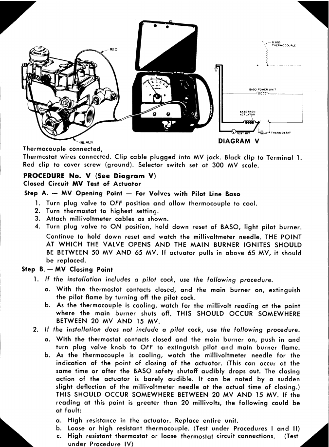
DIAGRAM V
BLftCK
Thermocouple connected,
Thermostat wires connected. Clip cable plugged into MV lack. Black clip to Terminal 1.
Red clip to cover screw (ground). Selector switch set at 300 MV scale.
PROCEDURE No. V (See Diagram V)
Closed Circuit MV Test of Actuator
Step A. - MV Opening Point - For Valves with Pilot Line Baso
Turn plug valve to OFF position and allow thermocouple to cool.
Turn thermostat to highest setting.
Attach millivoltmeter cables as shown.
Turn plug valve to ON position, hold down reset of BASO, light pilot burner.
Continue to hold down reset and watch the millivoltmeter needle. THE POINT
AT WHICH THE VALVE OPENS AND THE MAIN BURNER IGNITES SHOULD
BE BETWEEN 50 MV AND 65 MV. If actuator pulls in above 65 MV, it should
be replaced.
Step B. - MV Closing Point
1. If the installation includes a pilot cock, use the following procedure.
With the thermostat contacts closed, and the main burner on, extinguish
the pilot flame by turning off the pilot cock.
As the thermocouple is cooling, watch for the millivolt reading at the point
where the main burner shuts off. THIS SHOULD OCCUR SOMEWHERE
BETWEEN 20 MV AND 15 MV.
2. If the installation does not include a pilot cock, use the following procedure.
With the thermostat contacts closed and the main burner on, push in and
turn plug valve knob to OFF to extinguish pilot and main burner flame.
As the thermocouple is cooling, watch the millivoltmeter needle for the
indication of the point of closing of the actuator. (This can occur at the
same time or after the BASO safety shutoff audibly drops out. The closing
action of the actuator is barely audible. It can be noted by a sudden
slight deflection of the millivoitmeter needle at the actual time of closing.)
THIS SHOULD OCCUR SOMEWHERE BETWEEN 20 MV AND 15 MV. If the
reading at this point is greater than 20 millivolts, the following could be
at fault:High resistance in the actuator. Replace entire unit.
Loose or high resistant thermocouple. (Test under Procedures I and II)
High resistant thermostat or loose thermostat circuit connections. (Test
under Procedure IV) .4

SERVICE test procedures for
BASOTRON with
INTEGRAL Thermostats
15

Pr
Poor MV output.
Excessive draft.
Recirculation of flue
prod ucts.
Excessive tempera-
tu re.
Improper pilot
flame size or char-
acteristic.
Defective thermocouple.
Weak holding BASO
power unit.
Insufficient MV output.
Weak or defective ther-
mocouple.
Defective thermostat.
Defective actuator.
Use Test Procedure I.
Baffle secondary air or
shield pilot burner.
Check venting and main
burner orifice sizing
and correct where nec-
essary.
Check main burner in-
put and correct if nec-
essa ry.
Check gas pressure,
clean pilot burner, and
adjust flame.
Test thermocouple under
Test Procedures I and II on
page 2.
Test under Procedure 2.
Use Test Procedure lB.
(Check and correct as in
(a) through (d) above.)
Use Test Procedure Iand
II on page 2. Replace
thermocouple if necessary.
Use Test Procedure Ill.
Replace as indicated.
Use Test Procedure Ill.
Replace if necessary.
CONDITION
Pilot burner outage or
varying performance.
Pilot burner burning, plug
valve knob turned to ON
position, thermostat call-
ing for heat. Main burner
does not come on.
Thermostat not calling for
heat, or turned way
down, plug valve knob in
ON position - main
burner will not shut off.
SERVICE SUGGESTIONS
POSSIBLE CAUSE
Shorted thermostat cir-
Cu it.
Foreign particles
lodged between valve
seat.
16
REMEDY
Use Test Procedure Ill.
Remove actuator and clean
valve seat.
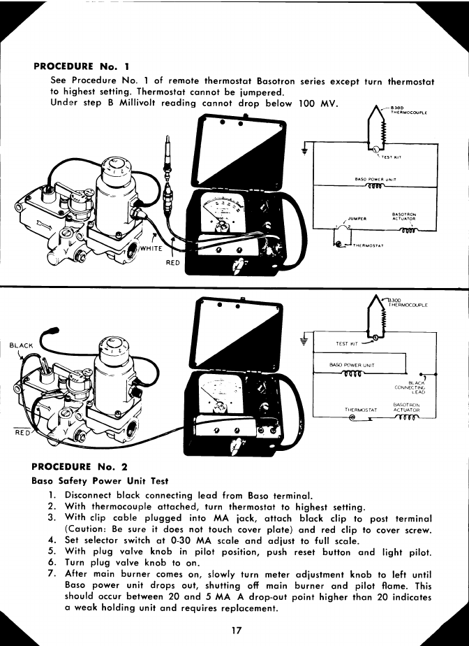
PROCEDURE No. 1
See Procedure No. 1of remote thermostat Basotron series except turn thermostat
to highest setting. Thermostat cannot be jumpered.
Under step B Millivolt reading cannot drop below 100 MV. A.-83ODTHERMOCOUPLE
17
3OD
T HERMOCcXJPLE
PROCEDURE No. 2
Baso Safety Power Unit Test
Disconnect black connecting lead from Baso terminal.
With thermocouple attached, turn thermostat to highest setting.
With clip cable plugged into MA jack, attach black clip to post terminal
(Caution: Be sure it does not touch cover plate) and red clip to cover screw.
Set selector switch at 0-30 MA scale and adjust to full scale.
With plug valve knob in pilot position, push reset button and light pilot.
Turn plug valve knob to on.
After main burner comes on, slowly turn meter adjustment knob to left until
Baso power unit drops out, shutting off main burner and pilot flame. This
should occur between 20 and 5 MA A drop-out point higher than 20 indicates
a weak holding unit and requires replacement.
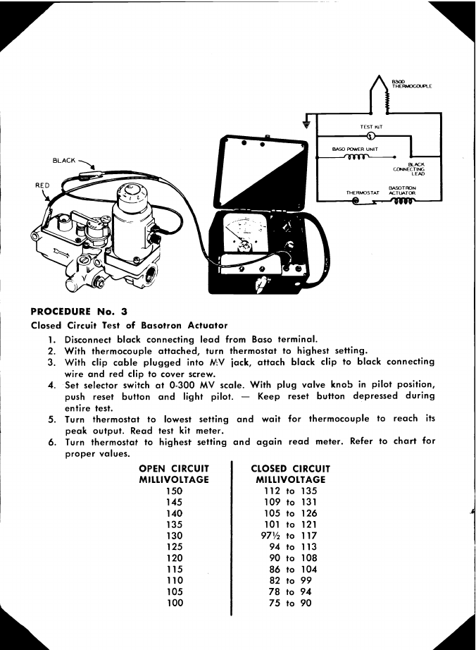
PROCEDURE No. 3
Closed Circuit Test of Basotron Actuator
Disconnect black connecting lead from Baso terminal.
With thermocouple attached, turn thermostat to highest setting.
With clip cable plugged into MV jack, attach black clip to black connecting
wire and red clip to cover screw.
Set selector switch at 0-300 MV scale. With plug valve knob in pilot position,
push reset button and light pilot. - Keep reset button depressed during
entire test.
Turn thermostat to lowest setting and wait for thermocouple to reach its
peak output. Read test kit meter.
Turn thermostat to highest setting and again read meter. Refer to chart for
proper values. OPEN CIRCUIT
MILLI VOLTAGE
150145140135130125120115110105100
CLOSED CIRCUIT
MI LLIVOLTAGE
112 to 135
109 to 131
105 to 126
101 to 121
97½ to 117
94 to 113
90 to 108
86 to 104
82 to 99
78 to 94
75 to 90

If the closed circuit millivoltage reading is greater than the maximum value
given in the chart, it indicates high resistance thermostat contacts or a faulty
internal connection. A reading equal to the open circuit reading indicates a
loss of fill in the thermostat or an open circuit in the actuator coil. If the
closed circuit millivoltage reading is less than the minimum value given in the
chart, it indicates a shorted actuator coil or a defective thermocouple. The
thermocouple should be checked according to procedure No. 1. The rest of
the indicated faults require replacement of the Basotron actuator.
REPLACEMENT PARTS LIST
REPLACEMENT ITEM
Adapter Nut - No. 1
Adapter Nut - No. 2
Lead Adapter - No. 4
Split Nut Adapter - No. 3
Red Cable
White Cable
Black Cable
Clip Cable
Adiusting Knob
Selector Knob
Fixed Load Adapter "A"
Closed Circuit Adapter "B"
19
PART No.
31543-1
31543.2
4248 3-1
40073-3
44549.3
44549-6
44549-7
44549.4
44589.1
90409.6
903 89-6
90379-6
Order
byPart Number
Shown

BA S 0 Milwaukee 1, Wiscdnsin
INC.
"Pioneers in thermoelectric gas controls"
Litho in U.S.A. 20007-603 REV. 1-61
t
January 1961
Table of contents
Other Baso Test Equipment manuals


