11.Presser foot lifting set mechanism(Option parts) 44
12.Driver copmponents 45
13.Accessories for model WF3955-45DD,WF3955-45AUT 46
CONTENTS
Operation
instruction
1.Brief introduction
...........................................................................................
1
2.Machine specification
......................................................................................
1
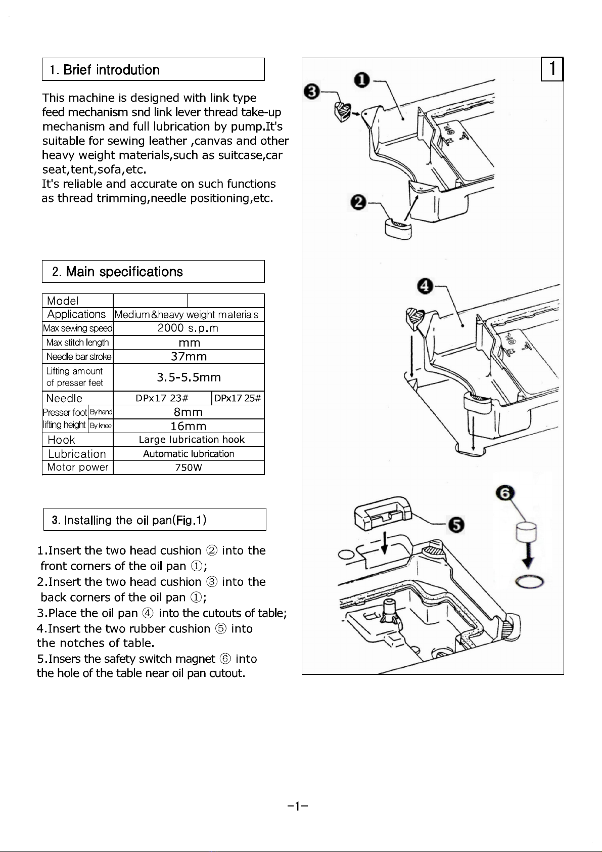
3.Installing
the
oil pan
.................................................................
•·····················
1
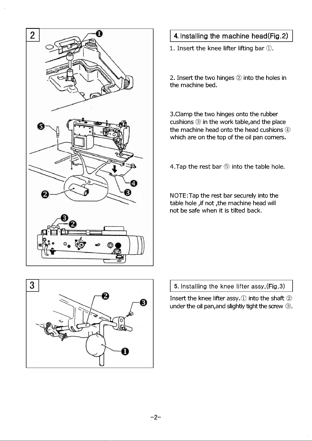
4.Installing
the
machine head
............................................................................
2
5.Installing
the
knee lifter assy
...........................................................................
2
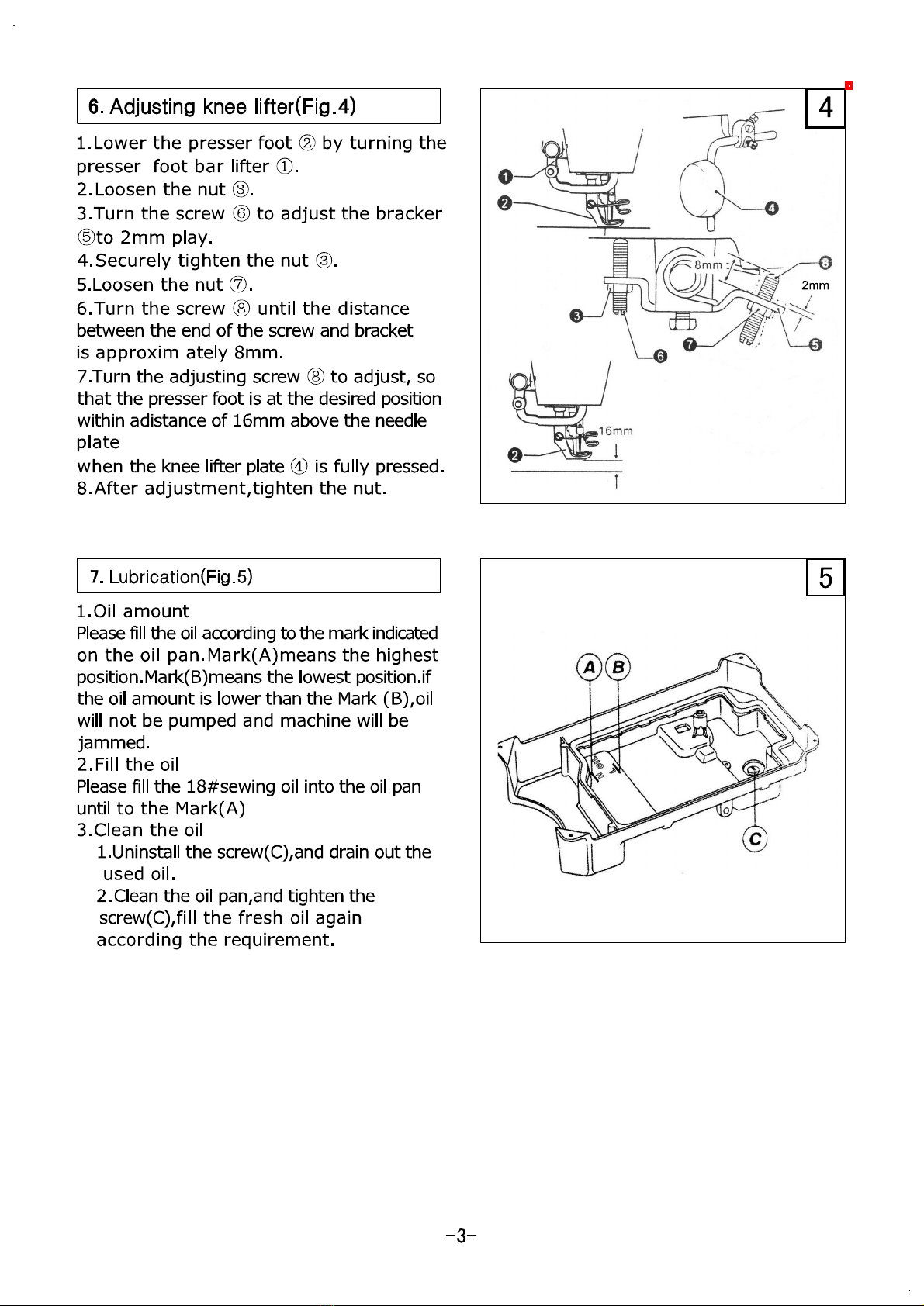
6.Adjusting
the
knee lifter
..................................................................................
3
7.Lubrication
....................................................................................................
3
8.Test operation
...............................................................................................
4
9.Installing
the
needle
.......................................................................................
s
10.Removing
the
bobbin case
.............................................................................
5
11.Winding
the
bobbin thread
............................................................................
s
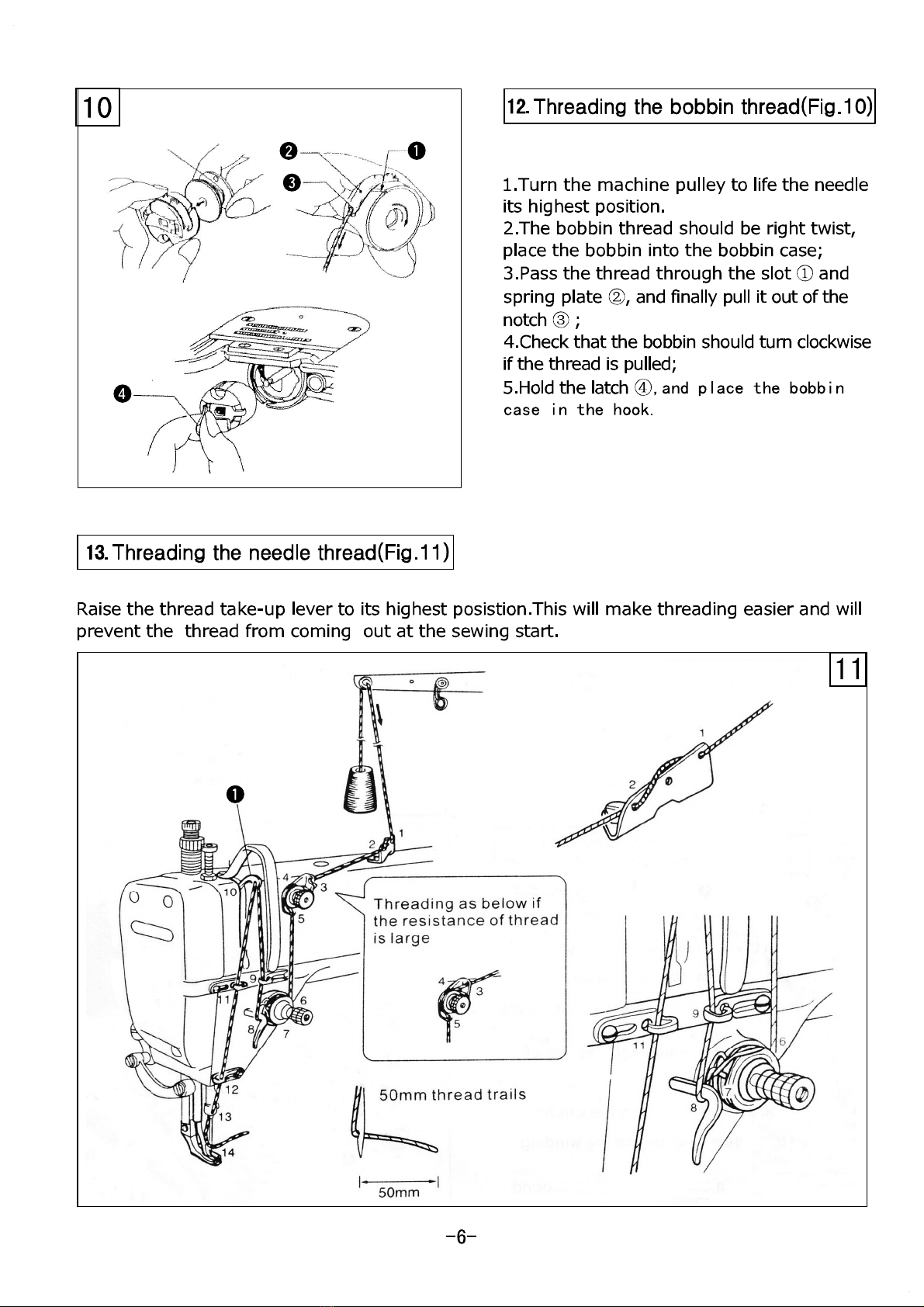
12.Threading
the
bobbin thread
..........................................................................
6
13.Threading
the
needle thread
..........................................................................
6
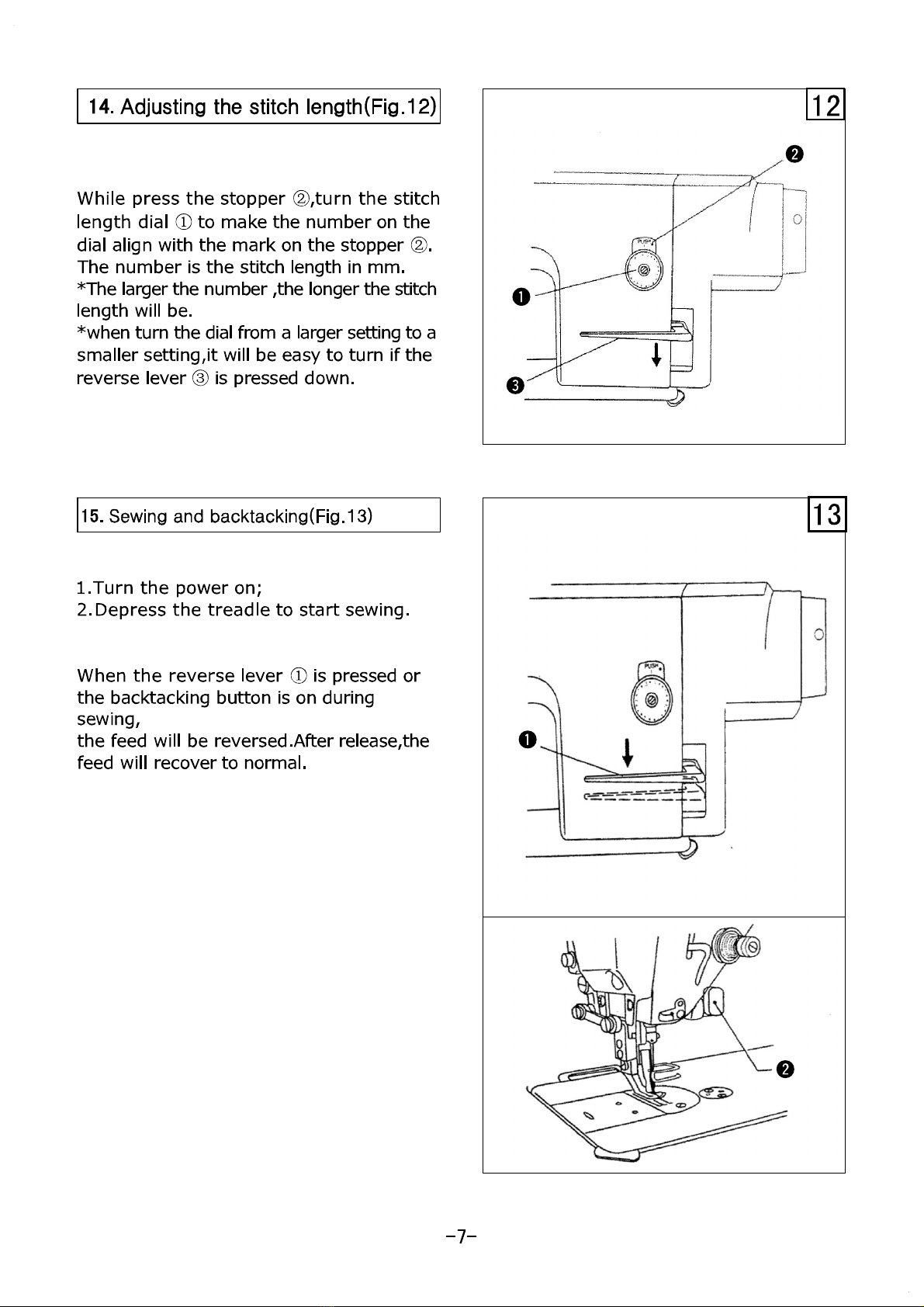
14.Adjusting
the
stitch length
.............................................................................
7
15.Sewing and backtacking
................................................................................
7
16.Adjusting
the
thread tension
..........................................................................
8
17.Adjusting
the
presser
foot
pressure
................................................................
8
18.Adjusting
the
trailing length
after
thread
trimming
...........................................
g
19.Adjusting
the
thread tension spring
................................................................
g
20.Adjusting
the
upper thread guide
..................................................................
10
21.Adjusting
the
presser
foot
height
..................................................................
10
22.Adjusting
the
feed dog height
......................................................................
10
23.Adjusting
the
feed dog angle
.......................................................................
11
24.Adjusting
the
difference
of
stitch length between the forward
and
backtacking
............
11
25.Adjusting
the
tension release
.......................................................................
11
26.Adjusting
the
timing
of
needle and feed mechanism
........................................
12
27.Adjusting
the
rotary
hook lubrication
amount
.................................................
12
28.Adjusting
the
height
of
needle
of
needle bar and the timing with hook
..................
13
29.Adjusting
the
oil pump
................................................................................
13
30.Adjusting
the
lifting
amount
of
presser feet
....................................................
14
31.Adjusting
the
trimming
mechanism
..........................................................
15-16
32.Clean
........................................................................................................
17
Parts
Manual
1.Casting mechanism
..................................................................................
18-21
2.Needle
bar
and thread
take-up
mechanism
..................................................
22-23
3.Presser foot mechanism
............................................................................
24-25
4.Feed mechanism
......................................................................................
26-29
5.Upper feed mechanism
.............................................................................
30-31
6.Hook mechanism
.....................................................................................
32-33
7.Lubrication mechanism
..............................................................................
34-35
8.Thtead
trimming
mechanism
......................................................................
36-39
9.Reverse stitching mechanism
.....................................................................
40-41
10.Accessories
for
model
.............................................................................
42-43
From the library of Superior Sewing Machine & Supply LLC - www.supsew.com