manuals.online logo
Brands
  1. Home
  2. •
  3. Brands
  4. •
  5. Baumer
  6. •
  7. Accessories
  8. •
  9. Baumer qTarget OT500 User manual

Baumer qTarget OT500 User manual

Connection Diagrams
*Only models with IO-Link
See packaging label for the specifi c wiring of your product
- Disconnect power before connecting the sensor.
- Voltage supply according UL 1310, Class 2
or device shall be protected by an external R/C or listed fuse, rated max.
30 VAC/3A or 24 VDC/4A
4
0V
21
3
+Vs
5
Distance measuring
sensors
Background suppres-
sion sensors
SmartRefl ect light
barriers
OT500.D OT500.G OT500.S
1 - Brown BN +Vs
2 - White WH
Analog U or I
Output 2 or
complementary to
Output 1
Output 2 (quality
bit) or
complentary to
Output 1
3 - Blue BU 0 V
4 - Black BK IO-Link* / Output 1
5 - Grey GY Teach-in / control
M12
Photoelectric sensors
OT500
Baumer Electric AG - CH-8501 Frauenfeld
Phone +41 (0)52 728 1122 - Fax +41 (0)63 739 1144
www.baumer.com
qTarget ®
qTeach ®
13.12.2021/ Version 1.0
11247884
EN
DE
FR
IT
ES
CN
Available Commands:
Teach-In commands, light emission on/off , Find Me (locating
sensor) and more
Available Parameters:
Switching point, switching hysteresis, output function, time
fi lters, measured value fi ltering, analog output characteristic,
qTeach lock time, LED status indicators and more
Available Additional Data:
Switch counts, temperature, boot cycles, operating hours,
device temperature, operating voltage, histograms
Models with IO-Link
SSC1/2/4: Switching Signal Channels
MDC: Distance value, quality value or switch counts
(selectable)
Quality: The quality bit signals a weak signal
Alarm: The alarm bit signals a problem with the
confi guration or the functionality of the sensor
Scale: Factor by power of ten, applicable to the value of
the Measurement Data Channel (MDC)
IO-Link Process Data Input
16 8 0
IntegerT(16) IntegerT(8) 8 bit
Measurement
Data Channel
(MDC)
Scale Baumer specifi c
76543210
SSC4 Alarm Quality SSC2 SSC1
Alignment Aid
n
Faster fl ashing
→ stronger signal
OT500.S light barriers are equipped with an alignment aid,
which is integrated in Teach Level 1.
The alignment aid indicates the strength of the received
signal.
OT500.S Lichtschranken verfügen über eine Ausrichthilfe.
Diese ist im Teach Level 1 integriert und zeigt die Stärke des
empfangenen Signals an.
Les barrières lumineuses OT500.S sont équipées d’un outil
d’aide à l’alignement, qui est intégré au niveau 1 de la procé-
dure de teach.
L’aide à l’alignement indique la force du signal reçu.
Le barriere fotoelettriche OT500.S sono dotate di indicazione
di corretto allineamento. Questa funzione è integrata nel
livello 1 di Teach-In e viene indicata l‘intensità del segnale
ricevuto.
OT500.S轻障的配备了对准辅助功能, 集成在设定级别1中.
对准辅助表明了接收信号的强度.
Las barreras de luz OT500.S están equipadas con una ayuda
de alineado integrada en el Nivel 1 de Teach.
La ayuda de alineado indica la potencia de señal recibida.
Sensor ausrichten, schnelles Blinken, besserer Empfang
Align sensor, faster fl ashing, better reception
Aligner le capteur, clignotement plus rapide, meilleure est la
réception
Allineamento del sensore: più è veloce il lampeggiamento
tanto più è forte il segnale
Sensor alineado, parpadeo más rápido, mejor recepción
对准传感器,闪烁越快,接收得更好
Related Models
OT500 Models:
OT500.D* (Distance measuring sensors)
OT500.G* (Background suppression sensors)
OT500.S* (SmartRefl ect light barriers)
More Information related to these
products can be found on our website
(CAD, Beamcharts, CoC, Drawings, IODDs …)
www.baumer.com
Mounting Instructions
It is recommended that the object to be detected approaches the active area of
the sensor from the side.
This may avoid malfunctions caused by defl ection of the light beam at edges.
Exception: Sensors with line beam
qTarget®
The Baumer design aligns the sensor‘s light beam to
the fi xing holes (qTarget®).
This allows a fast and easy installation without
fi ne-tuning as well as fast exchange.
Teach-in OK
Teach-in NOK
2 sec / Level 1
4 sec / Level 2
6 sec / Level 3
8 sec / Level 4
8888
X
1 11
2 22
2 2
2 2
Idle 60 sec
Idle 60 sec
OT500.S
OT500.D
OT500.G with 2 outputs
OT500.G
Idle 60 secIdle 60 sec
Idle 60 sec
Idle 4 sec
Enter Teach Level
- Place ferromagnetic tool as shown right to
activate qTeach
®
or connect Teach-In wire to +Vs
- The blue LED gets brighter if tool / Teach-In is
recognized properly
- Remove after n sec for desired level
A TAP is a short touch (>100 ms) of the tool as
shown right
General Information
- qTeach® locks 5 min after power up*
- If locked, qTeach® can be reactivated by re-apply-power or
by connecting the Teach-In wire for >15 sec. to +Vs
- External teach-in is always possible (no locking)
- In teach mode the output changes to 0V
- During operation the teach wire should be connected to 0V
- For external Teach-In connect Teach-In to +Vs
Alignment Aid
Place object & TAP
1- Point Teach
Place object at
position A & TAP
Place object at
position B & TAP
Output Logic TAP to change
setting
Optional: Hold 2
sec to change to
output 2
TAP to change
setting
Factory Reset Do nothing for factory reset
Teach-in Instruction
Indication Logic
NO, out 1
NC, out 1
Indication Logic
NO, out 2
NC, out 2
1- Point Teach
Output 2
Scanning Range /
Window Teach
Align the sensor to
the reference & TAP
Place object & TAP
After each defi ned idle time, the sensor returns to
operation mode.
Place tool >2 sec : Leave Teach-In immediately
without changes
>12 sec: Sensor turns to operation mode without any changes
1
2
8
Reference
Tolerance +/-*
sensing range, Sa
Teach-Position
Sensing direction
+TPO*
1
8
8
10 V /
20 mA
10 V /
20 mA
0 V /
4 mA
0 V /
4 mA
A < B A > B
Teach-Position
Sensing direction
+TPO*
Teach-Position
Sensing direction
+TPO*
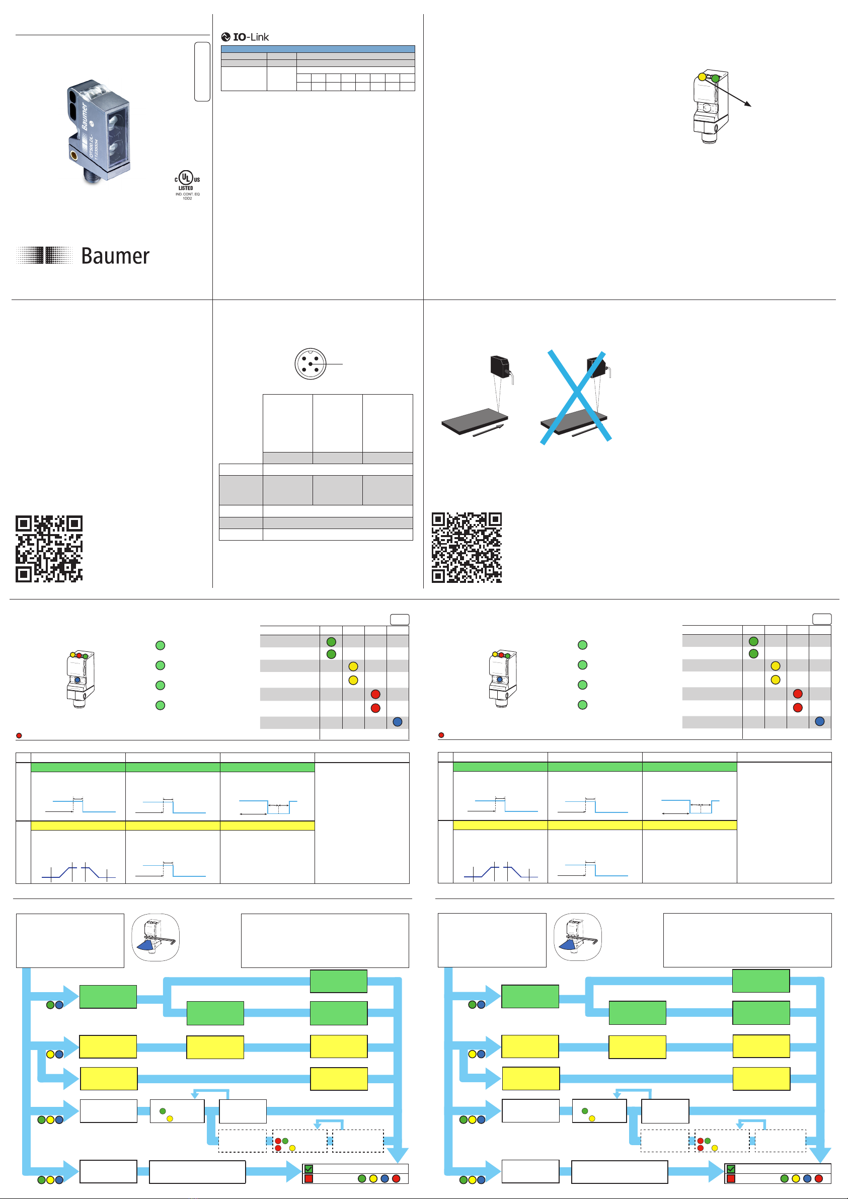
LED Indication Legend Operating Mode
LED on
LED fl ashing 1 Hz
LED fl ashing 2 Hz
LED fl ashing 8 Hz
OT500.D, Distance measuring
OT500.G, Background suppression OT500.S, SmartRefl ect light barriers Optional Teach-In methods*
Level 1
1-Point Teach 1-Point Teach: Output 1 1-Point Teach Pre-confi gurable via IO-Link
Window mode (OT500.D, OT500.G)
Level 1 / 1-Point Teach:
Sets a window of +/- 5% (TPO*) around
the position of the object
Level 2 / 2-Point Teach:
Sets a window of +/- 5%* around the
position of the object
Sets the switchpoint at the position of
the object +TPO* (teach point off set)
TPO: See packaging (typ. 5%)
Sets the switchpoint at the position of
the object + TPO* (teach point off set)
TPO: See packaging (typ. 5%)
Teaches the position of the
reference (distance)
Tolerance: See packaging (typ.+/- 10%)
Level 2
Scanning Range / Window Teach
1-Point Teach: Output 2 Not active
Set the scanning range related
to the analogue value. Output 1
is active if an object is within the
scanning range
Sets the switchpoint at the position of
the object + TPO* (teach point off set)
TPO: See packaging (typ. 5%)
For SmartRefl ect Light barriers, the
teach level 2 is not active
If level 2 is entered, the sensor leaves
the level immediately without any
changes
Teach-In Description Level 1 & 2
Englisch
*This value is adjustable by IO-Link. Please check the IO-Link manual available on www.baumer.com
LED Indicators Green Yellow Red Blue
Power on
Short circuit
Output 1 active
Output 1 signal close
to threshold
Output 2 active
Output 2 signal close
to threshold
qTeach not locked
Teach-in mode see Teach-in Instruction
EN
Only sensors with 2 outputs do have a red LED
1
2
8
Reference
Tolerance +/-*
sensing range, Sa
Teach-Position
Sensing direction
+TPO*
1
8
8
10 V /
20 mA
10 V /
20 mA
0 V /
4 mA
0 V /
4 mA
A < B A > B
Teach-Position
Sensing direction
+TPO*
Teach-Position
Sensing direction
+TPO*
LED Anzeige Legende Betriebsmodus
LED leuchtet
LED blinkt 1 Hz
LED blinkt 2 Hz
LED blinkt 8 Hz
OT500.D, Distanzmessend OT500.G, Hintergrundausblendung OT500.S, SmartRefl ect Lichtschranken Optionale Teach-In Modi*
Level 1
1-Punkt Teach 1-Punkt Teach: Ausgang 1 1-Punkt Teach Voreinstellbar per IO-Link
Fenster-Modus (OT500.D, OT500.G)
Level 1/ 1-Punkt Teach:
Defi niert ein Fenster à +/- 5% (TPO*) um
die Position des Objektes
Level 2 / 2-Punkt Teach:
Defi niert ein Schaltfenster, innerhalb wel-
chem ein Objekt erkannt werden soll
Setzt den Schaltpunkt an der Position
des Objektes + TPO*
(Teach point off set, typ. 5%)
Setzt den Schaltpunkt an der Position
des Objektes + TPO*
(Teach point off set, typ. 5%)
Lernt die Position der Referenz ein
(Distanz)
Tolerance:
Siehe Verpackung (typ. +/- 10%)
Level 2
Messbereich / Fenster Teach
1-Punkt Teach: Ausgang 2 Nicht aktiv
Defi niert den mit dem analogen
Ausgang verknüpften Messbereich.
Ausgang 1 ist aktiv, wenn sich ein
Objekt innerhalb des Messbereichs
befi ndet
Setzt den Schaltpunkt an der Position
des Objektes + TPO*
(Teach point off set, typ. 5%)
Für die SmartRefl ect Lichtschranken ist
das Level 2 nicht aktiv
Wird das Teach-Level 2 ausgewählt,
verlässt der Sensor den Teach-In
Modus ohne jegliche Änderungen
Teach-In Beschreibung Level 1 & 2
DE
*Dieser Wert kann per IO-Link verändert werden. Weitere Details fi nden Sie im IO-Link Manual verfügbar auf www.baumer.com
LED Indikatoren Grün Gelb Rot Blau
Betriebsanzeige
Kurzschluss
Ausgang 1 aktiv
Ausgang 1 Signal
nahe der Schwelle
Ausgang 2 aktiv
Ausgang 2 Signal
nahe der Schwelle
qTeach verwendbar
Teach-in Modus siehe Teach-in Anweisung
Nur Sensoren mit 2 Ausgängen verfügen über eine rote LED
Teach-in OK
Teach-in NOK
2 sec / Level 1
4 sec / Level 2
6 sec / Level 3
8 sec / Level 4
8888
X
1 11
2 22
2 2
2 2
Idle 60 sec
Idle 60 sec
OT500.S
OT500.D
OT500.G with 2 outputs
OT500.G
Idle 60 secIdle 60 sec
Idle 60 sec
Idle 4 sec
Allgemeine Information
- qTeach® verriegelt 5 min nach dem Einschalten*
- Falls gesperrt, kann qTeach® durch ein erneutes Einschalten oder
durch den Anschluss der Teach-In-Leitung für >15 Sek. an +Vs reaktiviert
werden
- Externes Teach-In ist immer möglich (keine Verriegelung)
- Im Teachmodus wechselt der Ausgang auf 0V
- Im Normalbetrieb muss die Teachleitung auf 0V gelegt werden
- Für externes Teach-in, Teachleitung entsprechend mit +Vs verbinden
1-Punkt Teach
Ausrichthilfe
Objekt platzieren
& TAP
Objekt platzieren an
Position B & TAP
1-Punkt Teach
out 2
Objekt platzieren
& TAP
Ausgangslogik TAP um Einstel-
lung zu ändern
Optional: 2 sec
halten -> zu Aus-
gang 2 wechseln
TAP um Einstel-
lung zu ändern
Werkseinstellungen Keine weiteren Eingriff e nötig
Teach Level auswählen
- Platziere das ferromagnetische Werkzeug wie
rechts dargestellt um qTeach® zu aktivieren oder
verbinde die Teachleitung mit +Vs
- Die blaue LED leuchtet auf, wenn das
Werkzeug korrekt erkannt wird
- Nach n Sek. entfernen, um das gewünschte Level
auszuwählen
Ein TAP ist eine kurze Berührung (>100 ms) des
Werkzeugs
Teach-in Anleitung
Indikation Logik
NO, out 1
NC, out 1
Indikation Logik
NO, out 2
NC, out 2
Objekt platzieren an
Position A & TAP
2-Punkt Teach /
Fenster
Den Sensor zur
Referenz ausrichten
& TAP
Nach der defi nierten Idle-Zeit kehrt der Sensor in
den Betriebsmodus zurück.
Werkzeug platzieren >2 Sek.: Verlasse Teach-In
ohne Änderungen.
>12 Sek: Sensor geht ohne Änderung in den Betriebsmodus über
1
2
8
Reference
Tolerance +/-*
sensing range, Sa
Teach-Position
Sensing direction
+TPO*
1
8
8
10 V /
20 mA
10 V /
20 mA
0 V /
4 mA
0 V /
4 mA
A < B A > B
Teach-Position
Sensing direction
+TPO*
Teach-Position
Sensing direction
+TPO*
Indication LED Légende Mode de fonctionnement
LED ON
LED clignotante 1 Hz
LED clignotante 2 Hz
LED clignotante 8 Hz
OT500.D, Mesure de la distance OT500.G, Suppression d’arrière-plan OT500.S, Barrière SmartRefl ect Méthodes de Teach-in optionnelles*
Niveau 1
Teach 1-point Teach 1-point: Sortie 1 Teach 1-point Pre-confi gurable via IO-Link
Mode fenêtre (OT500.D, OT500.G)
Niveau 1/ Teach 1-point:
Régler une fenêtre de +/- 5% (TPO*)
autour de la position de l’objet
Niveau 2 / Teach 2-point
Régler une fenêtre dans laquelle l’objet
sera détecté
Régler le point de commutation à la
position de l’objet + TPO*
(Teach point off set, typ. 5%)
Régler le point de commutation à la
position de l’objet + TPO*
(Teach point off set, typ. 5%)
Apprendre la position de la référence
(distance)
Tolerance:
Voir l‘emballage (typ. +/- 10 %)
Niveau 2
Teach 2 Points / Fenêtre
Teach 1-point: Sortie 2 Pas active
Régler la zone de mesure corres-
pondante à la sortie analogique. La
Sortie 1 est active si l’objet est dans
la zone défi nie.
Régler le point de commutation à la
position de l’objet + TPO*
(Teach point off set, typ. 5%)
Pour la barrière SmartRefl ect, le Teach
niveau 2 n’est pas actif
Si le niveau 2 est activé, le capteur
quitte immédiatement ce niveau sans
changement
Description Teach-In Niveau 1 & 2
Französisch
FR
* Cette valeur est ajustable via IO-Link. Consultez le manuel IO-Link disponible sur www.baumer.com
Indicateurs LED Vert Jaune Rouge Bleu
Power On
Court-circuit
Sortie 1 activée
Sortie 1 signal proche
du seuil
Sortie 2 activée
Sortie 2 signal proche
du seuil
qTeach disponible
Mode Teach-In Voir Instructions Teach-In
Seuls les détecteurs avec 2 sorties ont une LED rouge
Teach-in OK
Teach-in NOK
2 sec / Level 1
4 sec / Level 2
6 sec / Level 3
8 sec / Level 4
8888
X
1 11
2 22
2 2
2 2
Idle 60 sec
Idle 60 sec
OT500.S
OT500.D
OT500.G with 2 outputs
OT500.G
Idle 60 secIdle 60 sec
Idle 60 sec
Idle 4 sec
Information Générale
- qTeach® se verrouille 5 min après la mise sous tension.
- S‘il est verrouillé, qTeach® peut être réactivé en réappliquant l‘alimentation ou
en connectant le fi l de Teach-In pendant >15 sec. à +Vs
- Le Teach externe est toujours disponible (Pas de verrouillage)
- En mode Teach la sortie est à 0V
- En mode normal l‘entrée Teach est à 0V
- Pour un Teach externe, connecter l‘entrée Teach correspondant au +Vs
Teach 1 Point
Aide d’alignement
Placer l’objet & TAP
Teach 2 Points /
Fenêtre
Placer l’objet à la
position B & TAP
Teach 1 Point
Sortie 2 Placer l’objet & TAP
Logique de
commutation TAP pour chan-
ger le réglage
Option: Maintenir
2 sec pour pas-
ser à la Sortie 2
Remise confi guration
usine Attendre pour la confi guration usine
Entrée en mode Teach:
- Placer l‘outil ferromagnétique comme indiqué
ci-contre pour activer qTeach® ou
connecter le fi l Teach-In au +Vs
- La LED bleu devient plus brillante si l‘outil / Teach-
in est reconnu correctement
- Enlever après n sec pour le niveau souhaité
Un TAP est une courte touche (>100 ms) de l‘outil
comme présenté ci-contre
Instructions Teach-In
TAP pour changer
le réglage
Indication Logique
NO, Sortie 1
NC, Sortie 1
Indication Logique
NO, Sortie 2
NC, Sortie 2
Placer l’objet à la
position A & TAP
Aligner le détecteur
sur la référence
& TAP
Après le temps d‘inactivité défi ni, le capteur revient
en mode de fonctionnement.
Placez l‘outil >2 sec : Quitter le Teach-In sans
modifi cations.
>12 sec : Le capteur se met en mode de fonctionnement sans aucune modifi cation
1
2
8
Reference
Tolerance +/-*
sensing range, Sa
Teach-Position
Sensing direction
+TPO*
1
8
8
10 V /
20 mA
10 V /
20 mA
0 V /
4 mA
0 V /
4 mA
A < B A > B
Teach-Position
Sensing direction
+TPO*
Teach-Position
Sensing direction
+TPO*
Indicazioni LED Legenda Modalità operativa
LED acceso
LED lampeggia a 1 Hz
LED lampeggia a 2 Hz
LED lampeggia a 8 Hz
OT500.D, Misurazione della distanza OT500.G, Sensori a soppressione di sfondo OT500.S, Sensori SmartRefl ect Confi gurazioni opzionali*
Livello 1
Teach a 1 punto Teach a 1 punto: Uscita 1 Teach a 1 punto
Pre-confi gurabile tramite IO-Link
Funzionamento a fi nestra
(OT500.D, OT500.G)
Livello 1/Teach 1 punto:
Viene impostata una fi nestra di +/-5% (TPO*)
relativa alla posizione dell’oggetto da rilevare
Livello 2/Teach a 2 punti:
Viene impostata una fi nestra tra due punti all’in-
terno dei quali l’oggetto deve essere rilevato
Impostazione del punto di commutazi-
one alla posizione desiderata + TPO*
(Teach point off set, typ. 5%)
Impostazione del punto di commutazi-
one alla posizione desiderata + TPO*
(Teach point off set, typ. 5%)
Teach-In della posizione dello sfondo
Tolerance: Vedere imballaggio
(typ. +/- 10%)
Livello 2
Teach del range di misura a 2 punti
Teach a 1 punto: Uscita 2 Non attivo
Impostare il range relativo all’uscita
analogica. Se l’uscita digitale non
viene impostata nel livello 1 rimane
sempre attiva all’interno del range
di misura.
Impostazione del punto di commutazi-
one alla posizione desiderata + TPO*
(Teach point off set, typ. 5%)
Per le fotocellule SmartRefl ect, il
Teach-In al livello 2 non è attivo
Accedendo a tale livello, non si apport-
ano modifi che
Descrizione dei livelli 1 e 2 Teach-In
IT
*Questo valore è modifi cabile via IO-Link. Consultare il manuale IO-Link disponibile sul sito www.baumer.com
Indicazioni LED Verde Giallo Rosso Blu
Power On
Corto circuito
Uscita 1 attiva
Uscita 1 prossima alla
soglia
Uscita 2 attiva
Uscita 2 prossima alla
soglia
qTeach utilizzabile
Modalità di Teach-In see Teach-In Instruction
Solo i sensori con 2 uscite hanno un LED rosso
Teach-in OK
Teach-in NOK
2 sec / Level 1
4 sec / Level 2
6 sec / Level 3
8 sec / Level 4
8888
X
1 11
2 22
2 2
2 2
Idle 60 sec
Idle 60 sec
OT500.S
OT500.D
OT500.G with 2 outputs
OT500.G
Idle 60 secIdle 60 sec
Idle 60 sec
Idle 4 sec
Selezionare il livello di Teach-In
-
Posizionare l‘utensile ferromagnetico come
mostrato a destra di attivare qTeach® o collegare
il cavo Teach-In a +Vs.
- L’illuminazione del LED blu aumenta di intensità se
l‘utensile/teach-in viene riconosciuto correttamente.
- Rimuovere dopo n sec. per il livello desiderato
TAP indica un breve tocco con l’utensile sul punto
di teach.
Informazione generali
- La funzione di qTeach ® si disattiva dopo 5min dall‘accensione del sensore*
- Se disabilitato qTeach® può essere riattivato mediante riapplicazione dell‘alimentazione
o collegando il fi lo Teach-In per >15 sec. a +Vs
- In modalità Teach-In l‘output assume un valore pari a 0V
- Il Teach-In da remoto è sempre possibile (non si disattiva dopo 5 min)
- Durante il normale funzionamento del sensore il cavo Teach-In va messo a 0V
- Per il Teach-In da remoto, connettere il cavo di teach a +Vs
Teach-in ad punto 1
Aiuto per l‘allinea-
mento
Posizionare oggetto
& TAP
Campo di misura /
Finestra
Teach-in ad punto 1
per uscita 2
Uscite logiche TAP modifi care
l’uscita
Opzionale:
Toccare 2 sec. In
piu per modifi care
l’uscita 2
TAP modifi care
l’uscita
Factory Reset Non toccare il punto di teach-in
Instrucciones Teach-In
Logica di indicazione
NO, fuori 1
NC, fuori 1
Logica di indicazione
NO, fuori 2
NC, fuori 2
Posizionare oggetto a
Posizione B & TAP
Posizionare oggetto a
Posizione A & TAP
Posizionare oggetto
& TAP
Allineare il sensore al
riferimento & TAP
Dopo il tempo di inattività defi nito, il sensore ritorna nel
modo operativo .
Riposizionare
l‘utensile >2 sec : Lasciare il Teach-In
senza modifi che.
>12 sec: Il sensore passa alla modalità di funzionamento senza alcuna modifi ca
Teach-in OK
Teach-in NOK
2 sec / Level 1
4 sec / Level 2
6 sec / Level 3
8 sec / Level 4
8888
X
1 11
2 22
2 2
2 2
Idle 60 sec
Idle 60 sec
OT500.S
OT500.D
OT500.G with 2 outputs
OT500.G
Idle 60 secIdle 60 sec
Idle 60 sec
Idle 4 sec
Información general
-qTeach® se bloquea 5 min después de la alimentación*
- Si está bloqueado, qTeach® puede ser reactivado volviendo a dar alimentación
o conectando el cable de Teach-In durante >15 seg. a +Vs
- El teach-in externo está siempre disponible (no se bloquea)
- En modo teach la salida cambia a 0V
- En modo normal el cable de teach se pone a 0V
- Para teach-in externo, conectar el cable teach a +Vs
1-point teach
Ayuda de alineado
Colocar Objeto & Tap
2 point teach/
Ventana
Colocar Objeto en
Posición A & Tap
Colocar Objeto en
Posición B & Tap
1 point teach
Salida 2 Colocar Objeto & Tap
Lógica de salida TAP para
cambiar
Opcional: Mantener
2 seg para cambiar a
Salida 2
TAP para cambiar
Reset a valores
fábrica Esperar a que se realice el Reset
Entrar en modo Teach:
- Coloque la herramienta ferromagnética como
indica la imagen para activar qTeach® o
conectar el cable Teach-In a +Vs
- El led Azul se ilumina si la herramienta o señal
teach-in se reconoce correctamente.
- Retirar tras n segundos para el nivel deseado
Un TAP es un toque corto (>100 ms) de la
herramienta
Instrucciones Teach-In
Indicación lógica
NO, salida 1
NC, salida 1
Indicación lógica
NO, salida 2
NC, salida 2
Alinear el sensor con
la referencia & Tap
Después del tiempo de inactividad defi nido, el
sensor vuelve al modo de funcionamiento.
Colocar la herramienta >2 seg : Dejar Teach-In
sin cambios.
>12 sec: El sensor pasa al modo de funcionamiento sin cambios
1
2
8
Reference
Tolerance +/-*
sensing range, Sa
Teach-Position
Sensing direction
+TPO*
1
8
8
10 V /
20 mA
10 V /
20 mA
0 V /
4 mA
0 V /
4 mA
A < B A > B
Teach-Position
Sensing direction
+TPO*
Teach-Position
Sensing direction
+TPO*
Información LED Leyenda Modo operativo
LED ON
LED parpadeo 1 Hz
LED parpadeo 2 Hz
LED parpadeo 8 Hz
OT500.D, Medición de la distancia OT500.G, con supresión de fondo OT500.S, Barreras SmartRefl ect Métodos Teach-In opcionales*
Nivel 1
1-Point Teach 1-Point Teach: Salida 1 1-Point Teach Pre-ajustable vía IO-Link
Modo ventana (OT500.D, OT500.G)
Nivel 1 / 1-Point Teach:
Defi ne una ventana de +/- 5% (TPO*)
alrededor de la posición del objeto
Nivel 2 / 2-Point Teach:
Defi ne una ventana donde se detectará
el objeto
Defi ne el punto de conmutación en la
posición del objeto + TPO*
(Teach point off set, typ. 5%)
Defi ne el punto de conmutación en la
posición del objeto + TPO*
(Teach point off set, typ. 5%)
Aprende la posición de la referencia
(Distancia)
Tolerance Ver embalaje (typ. +/- 10%)
Nivel 2
2-Point Teach/Ventana
1-Point Teach: Salida 2 No activo
Defi nir el intervalo de medición
respecto a la salida analógica. La
salida 1 se activa si detecta un
objeto dentro del intervalo.
Defi ne el punto de conmutación en la
posición del objeto + TPO*
(Teach point off set, typ. 5%)
Para las barreras SmartRefl ect, el nivel
2 no está activo
Si se entra en el nivel 2, el sensor deja
el nivel sin cambios inmediatamente
Descripción Teach-In Nivel 1 & 2
ES
*Éste valor es ajustable vía IO-Link. Por favor consulte el manual IO-Link disponible en www.baumer.com
LED Indicators green yellow red blue
Power On
Cortocircuito
Salida 1 activa
Salida 1 señal dentro
del intervalo
Salida 2 activa
Salida 2 señal dentro
del intervalo
qTeach disponible
Modo Teach-In Ver instrucciones Teach-In
Sólo los sensores con 2 salidas disponen de un LED rojo
1
2
8
Reference
Tolerance +/-*
sensing range, Sa
Teach-Position
Sensing direction
+TPO*
1
8
8
10 V /
20 mA
10 V /
20 mA
0 V /
4 mA
0 V /
4 mA
A < B A > B
Teach-Position
Sensing direction
+TPO*
Teach-Position
Sensing direction
+TPO*
LED 指示灯 图例 操作模式
LED 亮
LED 闪烁 1 Hz
LED 闪烁 2 Hz
LED 闪烁 8 Hz
OT500.D,距离测量 OT500.G,带背景抑制漫反射 OT500.S, 智能反射 可选的设定方式*
1级
1点设定 1点设定 输出 1 1点设定 通过IO-Link配置
窗口模式
(OT500.D, OT500.G)
1级/1点设定
设定大约在被测物±5% TPO*位置
的窗口
2级/2点设定
设定前后两个位置之间的窗口
动态模式
将开关点设置在被测物位置后TPO*
(Teach point off set)
TPO: 查看包裝 (通常為5%)
将开关点设置在被测物位置后TPO*
(Teach point off set)
TPO: 查看包裝 (通常為5%)
设定参考面的位置(距离)
Tolerance: 查看包裝 (通常為+/-10%)
2级
2点设定 1点设定 输出 2 未激活
设置与模拟值相对应的测量范围. 如
果被测物处于测量范围内, 则输出 1
处于激活状态
将开关点设置在被测物位置后TPO*
(Teach point off set)
TPO: 查看包裝 (通常為5%)
对于智能反射传感器, 2级设定
未被激活
如果进入2级设定, 传感器将在不做 不
做任何改动下立即离开该设定.
Teach-In 说明 1 级 & 2 级
CN
*这个值是通过IO-Link来调整的。请在 www.baumer.com 上查询IOLink手册
LED 指示灯 绿 黄 红 蓝
通电
短路
输出 1 激活
输出 1 信号接近阈值
输出 2 激活
输出 2 信号接近阈值
qTeach 可使用
Teach-in 模式 详见 Teach-in 说明
仅带2路输出的传感器有红色LED
Teach-in OK
Teach-in NOK
2 sec / Level 1
4 sec / Level 2
6 sec / Level 3
8 sec / Level 4
8888
X
1 11
2 22
2 2
2 2
Idle 60 sec
Idle 60 sec
OT500.S
OT500.D
OT500.G with 2 outputs
OT500.G
Idle 60 secIdle 60 sec
Idle 60 sec
Idle 4 sec
进入设定等级:
- 如右图所示放置金属工具或连接设定线至
+Vs
- 蓝色LED 变得更亮, 如果工具或设定被
正确识别
- 在 n 秒后档选定所需的等级 是拿开
触碰是如右图所示用工具快速靠近感应区域
总览:
- qTeach®开启5分钟后自行锁定
- 锁定之后,qTeach® 可以通过重新上电或者把外部示教线连接到
+Vs上大于15秒后进行激活
- 在设定模式下输出变至 0 V
- 在通常情况西设定先接至 0 V
- 对于外部设定, 将设定线连接至 +Vs
- 外部设定线永久有效 (无自锁)
1 点设定
对准辅助
放置被测物并触碰
2 点设定 /
窗口设定
将被测物放置于位置
A 并触碰
将被测物放置于位置
B 并触碰
1 点设定 输出 2
输出逻辑 触碰来改变设定
可选: 保持 2 秒改
变至输出 2 触碰来改变设定
恢复出厂设置 期间不进行任何设定
设定说明
指标逻辑
NO, 出1
NC, 出1
指标逻辑
NO, 出2
NC, 出2
放置被测物并触碰
将传感器对准反光板
并触碰
超出定义的时间后,传感器返回到正常工
作模式.
触碰大于2秒后离开,离开示教过程传感器
无改变
大于12秒:传感器返回正常工作模式且参数无任何变化

Other Baumer Accessories manuals

Baumer UNDK 10P8914/S35A User manual

Baumer

Baumer UNDK 10P8914/S35A User manual

Baumer PF55S User manual

Baumer

Baumer PF55S User manual

Baumer U500 User manual

Baumer

Baumer U500 User manual

Baumer OM70-11220169 User manual

Baumer

Baumer OM70-11220169 User manual

Baumer OM70T-11195786 User manual

Baumer

Baumer OM70T-11195786 User manual

Baumer OADM 20I6481/S14F User manual

Baumer

Baumer OADM 20I6481/S14F User manual

Baumer UNDK 20P7914/S35A User manual

Baumer

Baumer UNDK 20P7914/S35A User manual

Baumer OADR 20I6485/S14F User manual

Baumer

Baumer OADR 20I6485/S14F User manual

Baumer OADM 250I1101/S14C User manual

Baumer

Baumer OADM 250I1101/S14C User manual

Baumer 10161026 User manual

Baumer

Baumer 10161026 User manual

Baumer OADM 20I2472/S14C User manual

Baumer

Baumer OADM 20I2472/S14C User manual

Baumer 12P1914/S14D User manual

Baumer

Baumer 12P1914/S14D User manual

Baumer OBDM 12P6940/S35A User manual

Baumer

Baumer OBDM 12P6940/S35A User manual

Baumer UNDK 20N7914/S35A User manual

Baumer

Baumer UNDK 20N7914/S35A User manual

Baumer OM70-11220196 User manual

Baumer

Baumer OM70-11220196 User manual

Baumer UNAR 18N6912/S14G User manual

Baumer

Baumer UNAR 18N6912/S14G User manual

Baumer OADM 20U5440/S14C User manual

Baumer

Baumer OADM 20U5440/S14C User manual

Baumer UNAR 18N6912/S14G User manual

Baumer

Baumer UNAR 18N6912/S14G User manual

Baumer UNDK 20P6914/S35A User manual

Baumer

Baumer UNDK 20P6914/S35A User manual

Baumer URAR 12P8914/S14H User manual

Baumer

Baumer URAR 12P8914/S14H User manual

Baumer UNDK 20N6914/S35A User manual

Baumer

Baumer UNDK 20N6914/S35A User manual

Baumer UNDK 20N7903/S35A User manual

Baumer

Baumer UNDK 20N7903/S35A User manual

Baumer FZAM 18P6460/S14 User manual

Baumer

Baumer FZAM 18P6460/S14 User manual

Baumer OADM 20U2480/S14C User manual

Baumer

Baumer OADM 20U2480/S14C User manual

Popular Accessories manuals by other brands

NeuLog NUL-216 Guide

NeuLog

NeuLog NUL-216 Guide

EINHELL EGS12 operating instructions

EINHELL

EINHELL EGS12 operating instructions

Razor Jetts Mini instruction manual

Razor

Razor Jetts Mini instruction manual

Knick SE 554X AMSN Series manual

Knick

Knick SE 554X AMSN Series manual

ATEN VS92A Specifications

ATEN

ATEN VS92A Specifications

Omnicomm LLS 5 manual

Omnicomm

Omnicomm LLS 5 manual

Zinc ZN25152 User instructions

Zinc

Zinc ZN25152 User instructions

Ednet Power bank user manual

Ednet

Ednet Power bank user manual

Heatit Controls Z-HAN2 quick guide

Heatit Controls

Heatit Controls Z-HAN2 quick guide

Philips HF3505 user manual

Philips

Philips HF3505 user manual

NuTone PB340K installation guide

NuTone

NuTone PB340K installation guide

Orno SOUL DC Operating and instalation instructions

Orno

Orno SOUL DC Operating and instalation instructions

ZooZ ZEN06 VER. 2.0 user manual

ZooZ

ZooZ ZEN06 VER. 2.0 user manual

IFM OID20 Series operating instructions

IFM

IFM OID20 Series operating instructions

KROHNE OPTIFLUX 4000 Handbook

KROHNE

KROHNE OPTIFLUX 4000 Handbook

Mainstream CMZ60MEMO user guide

Mainstream

Mainstream CMZ60MEMO user guide

Vernier SMS-BTA Getting started and quick guide

Vernier

Vernier SMS-BTA Getting started and quick guide

Hytronik HIM31 Installation and instruction manual

Hytronik

Hytronik HIM31 Installation and instruction manual

manuals.online logo
manuals.online logoBrands
  • About & Mission
  • Contact us
  • Privacy Policy
  • Terms and Conditions

Copyright 2025 Manuals.Online. All Rights Reserved.