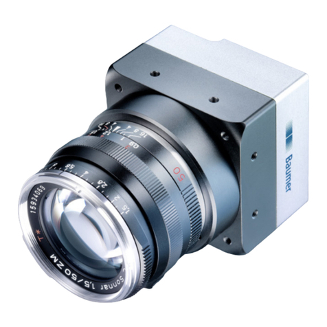
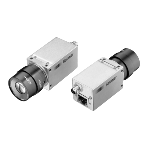
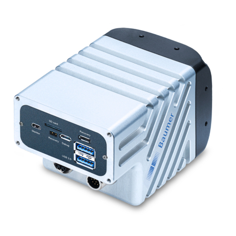
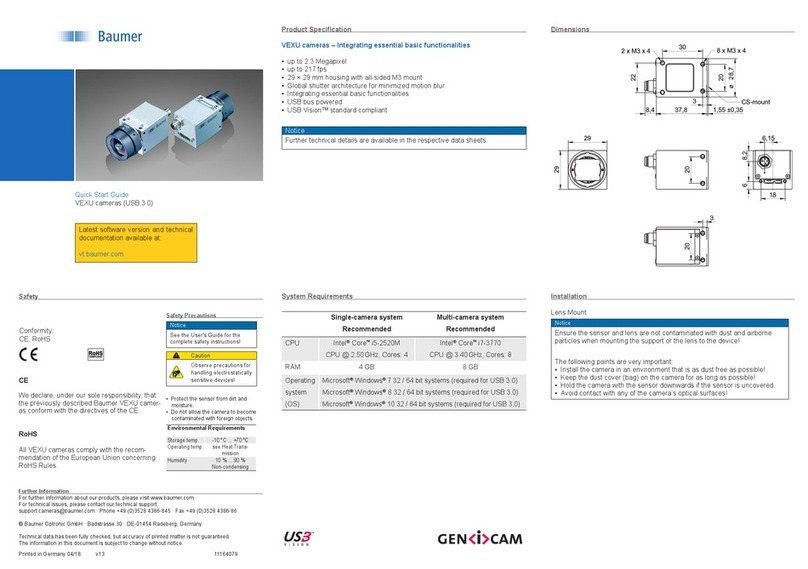
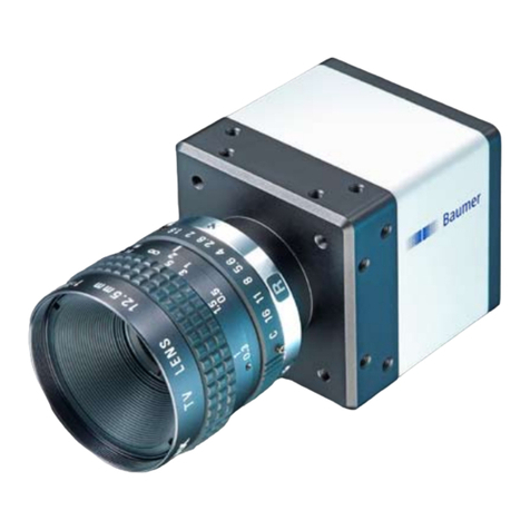
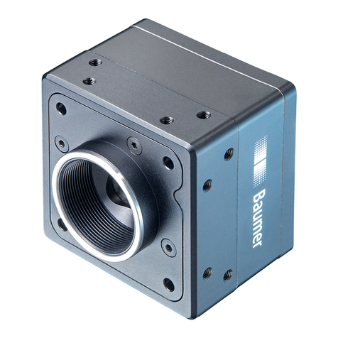
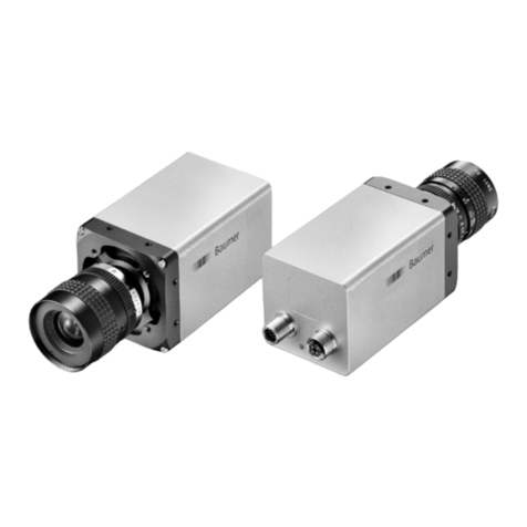
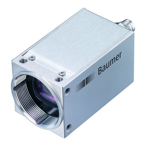
Baumer VCXG .I User manual

User´s Guide
VCXG / .I / .I.XT (Gigabit Ethernet) / VCXU (USB 3.0)
Document Version: v2.3
Release: 01.06.2018
Document Number: 11165414

2

3
Table of Contents
1. General Information ................................................................................................. 8
2. General Safety Instructions................................................................................... 10
3. Camera Models........................................................................................................11
3.1 VCXG.................................................................................................................... 13
3.2 VCXG.I / .I.XT ....................................................................................................... 15
3.3 VCXU .................................................................................................................... 19
4. Installation .............................................................................................................. 21
4.1 Environmental Requirements................................................................................ 21
4.2 Heat Transmission ............................................................................................... 21
4.2.1 Emergency shutdown at Overtemperature (≥ Rel. 2 only) ............................. 22
4.3 Lens mounting ...................................................................................................... 25
4.4 VCXG.I / .I.XT IP Protection classes..................................................................... 26
4.5 Filter replacement ................................................................................................. 27
4.6 Cleaning................................................................................................................ 28
4.7 Mechanical Tests................................................................................................... 29
5. Pin-Assignment / LED-Signaling .......................................................................... 30
5.1 VCXG.................................................................................................................... 30
5.1.1 Ethernet Interface (PoE)................................................................................. 30
5.1.2 Power Supply and IOs.................................................................................... 31
5.1.3 GPIO (General Purpose Input/Output) ........................................................... 31
5.1.4 Digital-IO......................................................................................................... 31
5.1.5 LED Signaling................................................................................................. 32
5.2 VCXG.I / .XT ......................................................................................................... 33
5.2.1 Ethernet Interface........................................................................................... 33
5.2.2 Power Supply and IOs.................................................................................... 33
5.2.3 Digital-IO ........................................................................................................ 34
5.2.4 LED Signaling................................................................................................. 35
5.3 VCXU .................................................................................................................... 36
5.3.1 USB 3.0 Interface ........................................................................................... 36
5.3.2 Digital-IOs....................................................................................................... 36
5.3.3 GPIO (General Purpose Input/Output) ........................................................... 37
5.3.4 LED Signaling................................................................................................. 38
6. ProductSpecications .......................................................................................... 39
6.1 Sensor Specications ........................................................................................... 39
6.1.1 Spectral Sensitivity ......................................................................................... 39
6.1.2 Sensor Shutter Mode (only cameras with Rolling Shutter sensor)................. 45
6.1.2.1 Global Reset .......................................................................................... 45
6.1.2.2 Rolling Shutter ........................................................................................ 46
6.2 Sensor position accuracy...................................................................................... 47
6.2.1 VCXG ............................................................................................................. 47
6.2.2 VCXG.I / .I.XT................................................................................................. 48
6.2.3 VCXU ............................................................................................................. 48
6.3 Acquisition Modes and Timings............................................................................. 49
6.3.1 Continuous Mode (Free Running Mode) ........................................................ 49

4
6.3.2 Single Frame Mode ........................................................................................ 50
6.3.3 Multi Frame Mode........................................................................................... 50
6.3.4 Acquisition Frame Rate Mode ........................................................................ 50
6.3.5 Trigger Mode .................................................................................................. 51
6.3.5.1 Overlapped Operation: texposure(n+2) = texposure(n+1) .............................. 52
6.3.5.2 Overlapped Operation: texposure(n+2) > texposure(n+1) .............................. 53
6.3.5.3 Overlapped Operation: texposure(n+2) < texposure(n+1) .............................. 54
6.3.5.4 Non-overlapped Operation...................................................................... 55
6.3.6 Timings of the image transmission ................................................................. 56
6.3.6.1 VCXG...................................................................................................... 56
6.3.6.2 VCXU...................................................................................................... 56
6.3.7 Advanced Timings for GigE Vision®/USB3 VisionTM Message Channel.......... 57
6.3.7.1 EventLost................................................................................................ 57
6.3.7.2 TriggerReady .......................................................................................... 57
6.3.7.3 TriggerSkipped........................................................................................ 57
6.3.7.4 TriggerOverlapped ................................................................................. 58
6.3.7.5 ReadoutActive......................................................................................... 58
6.3.7.6 TransferBufferFull .................................................................................. 59
6.3.7.7 TransferBufferReady .............................................................................. 59
6.3.7.8 DeviceTemperaturStatusChanged.......................................................... 60
6.4 Software................................................................................................................ 60
6.4.1 Baumer GAPI ................................................................................................. 60
6.4.2 3rd Party Software ........................................................................................... 60
7. Camera Functionalities.......................................................................................... 61
7.1 Image Acquisition.................................................................................................. 61
7.1.1 Image Format ................................................................................................. 61
7.1.1.1 VCXG /.I /.I.XT ........................................................................................ 61
7.1.1.2 VCXU...................................................................................................... 62
7.1.2 Pixel Format ................................................................................................... 63
7.1.2.1 General Denitions ................................................................................. 63
7.1.2.2 Pixel Formats VCXG / .I/.I.XT ................................................................. 64
7.1.2.3 Pixel Formats VCXU............................................................................... 65
7.1.3 Exposure Time................................................................................................ 67
7.1.3.1 VCXG / .I/.I.XT ........................................................................................ 68
7.1.3.2 VCXU...................................................................................................... 69
7.1.4 Fixed Pattern Noise Correction (FPNC) ......................................................... 70
7.1.4.1 VCXG / .I/.I.XT ........................................................................................ 70
7.1.4.2 VCXU...................................................................................................... 71
7.1.5 Look-Up-Table ................................................................................................ 72
7.1.6 Gamma Correction ......................................................................................... 72
7.1.7 Region of Interest ........................................................................................... 73
7.1.7.1 ROI.......................................................................................................... 73
7.1.8 Binning............................................................................................................ 74
7.1.8.1 Monochrome Binning.............................................................................. 74
7.1.8.2 Color Binning .......................................................................................... 75
7.1.9 Brightness Correction..................................................................................... 77
7.1.10 Flip Image..................................................................................................... 78
7.2 Color Processing................................................................................................... 79
7.3 Color Adjustment – White Balance ....................................................................... 79
7.3.1 User-specic Color Adjustment ...................................................................... 79
7.3.2 One Push White Balance (Once) ................................................................... 80
7.3.3 Continuous White Balance ............................................................................. 80
7.4 Analog Controls..................................................................................................... 80
7.4.1 Offset / Black Level......................................................................................... 80
7.4.1.1 VCXG / .I/.I.XT ........................................................................................ 80
7.4.1.2 VCXU...................................................................................................... 81
7.4.2 Gain................................................................................................................ 82
7.4.2.1 VCXG / .I/.I.XT ........................................................................................ 82
7.4.2.2 VCXU...................................................................................................... 83
7.5 Pixel Correction..................................................................................................... 84
5
7.5.1 General information........................................................................................ 84
7.5.2 Correction Algorithm....................................................................................... 85
7.5.3 Add Defect Pixel to Defectpixellist.................................................................. 86
7.6 Process Interface .................................................................................................. 87
7.6.1 Digital-IOs....................................................................................................... 87
7.6.1.1 User Denable Inputs ............................................................................. 87
7.6.1.2 General Purpose Input/Output - GPIO (except VCXG.I/.I.XT) ............... 88
7.6.1.3 Congurable Outputs.............................................................................. 89
7.6.1.4 Modes of Outputs (only VCXG.I / .XT).................................................... 90
7.6.1.5 Pulse Width Modulated Outputs (only VCXG.I/.I.XT).............................. 91
7.6.2 Trigger ............................................................................................................ 93
7.6.3 Trigger Source................................................................................................ 93
7.6.4 Debouncer...................................................................................................... 94
7.6.5 ExposureActive (Flash Signal) ....................................................................... 95
7.6.5.1 ExposureActiveDelay.............................................................................. 96
7.6.6 Timer............................................................................................................... 96
7.6.7 Counter (≥ Rel. 2 only)................................................................................... 97
7.7 Sequencer (≥ Rel. 2 only) ..................................................................................... 98
7.7.1 Sequencer sets .............................................................................................. 98
7.7.2 Sequencer conguration ................................................................................ 99
7.7.3 Sequencer command overview ...................................................................... 99
7.8 Device Reset....................................................................................................... 101
7.9 User Sets ............................................................................................................ 101
7.9.1 VCXG / .I/.I.XT.............................................................................................. 101
7.9.2 VCXU............................................................................................................ 102
7.10 Factory Settings ................................................................................................ 102
7.11 Timestamp......................................................................................................... 103
7.12 Chunk................................................................................................................ 104
7.13 Start-Stop-Behaviour ........................................................................................ 106
7.13.1 Start / Stop / Abort Acquisition (Camera).................................................... 106
7.13.2 Start / Stop Interface .................................................................................. 106
8. VCXG / .I / .I.XT – Interface Functionalities ........................................................ 107
8.1 Device Information .............................................................................................. 107
8.2 Packet Size and Maximum Transmission Unit (MTU)......................................... 107
8.3 Inter Packet Gap (IPG) ....................................................................................... 107
8.3.1 Example 1: Multi Camera Operation – Minimal IPG..................................... 108
8.3.2 Example 2: Multi Camera Operation – Optimal IPG..................................... 108
8.4 Transmission Delay............................................................................................. 109
8.4.1 Time Saving in Multi-Camera Operation ...................................................... 109
8.4.2 Conguration Example ..................................................................................110
8.5 Multicast...............................................................................................................112
8.6 IP Conguration ...................................................................................................113
8.6.1 Persistent IP ..................................................................................................113
8.6.2 DHCP (Dynamic Host Conguration Protocol) ..............................................113
8.6.3 LLA ................................................................................................................114
8.6.4 Force IP.........................................................................................................114
8.7 Packet Resend.....................................................................................................115
8.7.1 Normal Case..................................................................................................115
8.7.2 Fault 1: Lost Packet within Data Stream .......................................................115
8.7.3 Fault 2: Lost Packet at the End of the Data Stream ......................................116
8.7.4 Termination Conditions ..................................................................................116
8.8 Message Channel ................................................................................................117
8.8.1 Event Generation ..........................................................................................117

6
8.9 Action Command / Trigger over Ethernet.............................................................118
8.9.1 Example: Triggering Multiple Cameras .........................................................118
9. VCXU – Interface Functionalities .........................................................................119
9.1 Device Information ...............................................................................................119
9.2 Message Channel ............................................................................................... 120
9.2.1 Event Generation ......................................................................................... 120
9.3 Chunk................................................................................................................. 121

7

8
1. General Information
Thanks for purchasing a camera of the Baumer family. This User´s Guide describes how
to connect, set up and use the camera.
Read this manual carefully and observe the notes and safety instructions!
Support
In the case of any questions please contact our Technical & Application Support Center.
Worlwide: Baumer Optronic GmbH
Badstrasse 30
DE-01454 Radeberg, Germany
Tel: +49 (0)3528 4386 845
Website: www.baumer.com
E-mail: support.cameras@baumer.com
Target group for this User´s Guide
This User's Guide is aimed at experienced users, which want to integrate camera(s) into
a vision system.
Intended Use
The camera is used to capture images that can be transferred over a GigE interface
(VCXG /.I /.I.XT) or a USB 3.0 interface (VCXU) to a PC.
Classicationofthesafetyinstructions
In the User´s Guide, the safety instructions are classied as follows:
Notice
Gives helpful notes on operation or other general recommendations.
Caution
Pictogram
Indicates a possibly dangerous situation. If the situation is not avoided, slight
or minor injury could result or the device may be damaged.

9
Transport / Storage
Transport the camera only in the original packaging. When the camera is not installed,
then storage the camera in original packaging.
Disposal
Dispose of outdated products with electrical or electronic circuits, not in the
normal domestic waste, but rather according to your national law and the
directives 2002/96/EC and 2006/66/EC for recycling within the competent
collectors.
Through the proper disposal of obsolete equipment will help to save valu-
able resources and prevent possible adverse effects on human health and
the environment.
The return of the packaging to the material cycle helps conserve raw mate-
rials an reduces the production of waste. When no longer required, dispose
of the packaging materials in accordance with the local regulations in force.
Keep the original packaging during the warranty period in order to be able
to pack the device properly in the event of a warranty claim.
Warranty Notes
If it is obvious that the device is / was dismantled, reworked or repaired by other than
Baumer technicians, Baumer Optronic will not take any responsibility for the subsequent
performance and quality of the device!
Copyright
Any duplication or reprinting of this documentation, in whole or in part, and the reproduc-
tion of the illustrations even in modied form is permitted only with the written approval of
Baumer. The information in this document is subject to change without notice.

10
2. General Safety Instructions
Caution
Heat can damage the camera. Provide adequate dissipation of heat, to
ensure that the temperature does not exceed the value (see Heat Trans-
mission).
As there are numerous possibilities for installation, Baumer recommends
no specic method for proper heat dissipation, but suggest the following
principles:
▪operate the cameras only in mounted condition
▪mounting in combination with forced convection may provide proper heat
dissipation
Caution
Observe precautions for handling electrostatic sensitive devices!
Caution
Class A
The camera is a class A device (DIN EN 55022:2011). It can cause radio
interference in residential environments. Should this happen, you must take
reasonable measures to eliminate the interference.

11
3. Camera Models
All Baumer cameras of these families are characterized by:
Best image quality ▪Low noise and structure-free image information
Flexible image acquisition ▪Industrially-compliant process interface with parameter
setting capability
Fast image transfer VCXG
.I/.I.XT
▪Reliable transmission up to 1000 Mbit/sec
according to IEEE802.3
▪Cable length up to 100 m
▪ PoE (Power over Ethernet)
▪Baumer driver for high data volume with low
CPU load
▪High-speed multi-camera operation
▪GenICam™ and GigE Vision®compliant
VCXU ▪Reliable transmission at 5000 Mbit/sec
according to USB 3.0 (v1.0.1) standard
▪GenICam™ and USB3 VisionTM compliant
Perfect integration ▪Flexible generic programming interface (Baumer GAPI)
for all Baumer cameras
▪Powerful Software Development Kit (SDK) with sample
codes and help les for simple integration
▪Baumer viewer for all camera functions
▪GenICam™ compliant XML le to describe the camera
functions
▪Supplied with installation program with automatic
camera recognition for simple commissioning
Compact design ▪Light weight
▪ exible assembly
Reliable operation ▪State-of-the-art camera electronics and precision
mechanics
▪Low power consumption and minimal heat generation
Supported standards VCXG ▪ v2.0 (v1.2 backward compatible)
▪GenICamTM SFNC 2.1 ׀ Rel. 2.0: SFNC 2.3
VCXU ▪USB3 VisionTM 1.0.1
▪GenICamTM GenCP 1.1
▪GenICamTM SFNC 2.1 ׀ Rel. 2.0: SFNC 2.3
Conformity CE We declare, under our sole respon-
sibility, that the described Baumer
cameras conform with the directives
of the CE.
RoHS All VCX cameras comply with the
recommendation of the European
Union concerning RoHS rules.
KC Several of the described Baumer
VCX cameras conform with the di-
rectives of the Korean Conformity.
(see table on next page)

12
Korean Conformity (Registration of Broadcasting and Communication Equipments)
VCXG
Product Article No. Registration No. Date of Registration
Monochrome
VCXG-02M 11165842 MSIP-REI-BkR-VCXG-13M 2017-05-02
VCXG-13M 11164973 MSIP-REI-BkR-VCXG-13M 2017-05-02
VCXG-25M 11165829 MSIP-REI-BkR-VCXG-53M 2017-05-02
VCXG-32M 11165949 MSIP-REI-BkR-VCXG-51C 2017-05-02
VCXG-51M 11165952 MSIP-REI-BkR-VCXG-51C 2017-05-02
VCXG-53M 11151554 MSIP-REI-BkR-VCXG-53M 2017-05-02
VCXG-91M 11173890 MSIP-REI-BkR-VCXG-124M 2017-05-02
VCXG-124M 11172630 MSIP-REI-BkR-VCXG-124M 2017-05-02
Color
VCXG-02C 11165843 MSIP-REI-BkR-VCXG-13M 2017-05-02
VCXG-13C 11164974 MSIP-REI-BkR-VCXG-13M 2017-05-02
VCXG-25C 11165828 MSIP-REI-BkR-VCXG-53M 2017-05-02
VCXG-32C 11165950 MSIP-REI-BkR-VCXG-51C 2017-05-02
VCXG-51C 11165953 MSIP-REI-BkR-VCXG-51C 2017-05-02
VCXG-53C 11151555 MSIP-REI-BkR-VCXG-53M 2017-05-02
VCXG-91C 11173819 MSIP-REI-BkR-VCXG-124M 2017-05-02
VCXG-124C 11172609 MSIP-REI-BkR-VCXG-124M 2017-05-02
VCXU
Product Article No. Registration No. Date of Registration
Monochrome
VCXU-02M 11165914 MSIP-REI-BkR-VCXU13M 2017-04-18
VCXU-13M 11165908 MSIP-REI-BkR-VCXU13M 2017-04-18
VCXU-31M 11165812 MSIP-REI-BkR-VCXU-50M 2017-04-28
VCXU-50M 11151564 MSIP-REI-BkR-VCXU-50M 2017-04-28
VCXU-51M 11164500 MSIP-REI-BkR-VCXU-50M 2017-04-28
Color
VCXU-02C 11165913 MSIP-REI-BkR-VCXU13M 2017-04-18
VCXU-13C 11165907 MSIP-REI-BkR-VCXU13M 2017-04-18
VCXU-31C 11165813 MSIP-REI-BkR-VCXU-50M 2017-04-28
VCXU-50C 11151566 MSIP-REI-BkR-VCXU-50M 2017-04-28
VCXU-51C 11164501 MSIP-REI-BkR-VCXU-50M 2017-04-28
Release Version
Notice
IdenticationofReleaseversion
• Label on camera ("R2.0" is Release 2.0)
• Baumer GAPI 2.x Camera Explorer / Category: Device Control → Device Version
(Release 1: R1.x.x / Release 2: R2.x.x)

13
3.1 VCXG
2
3
1
No. Description No. Description
1Lens mount (C-Mount) 3Ethernet Port (PoE) / Signaling LED´s
2Power supply / Digital-IO
Camera Type Sensor
Size Resolution
Full
Frames1)
[max. fps]
Monochrome / Color
VCXG-02M / VCXG-02C 1/4" 640 × 480 595 ׀ 403
VCXG-04M / VCXG-04C 1/2.9" 720 × 540 439.5 ׀ 318
VCXG-13M / VCXG-13C 1/2" 1280 × 1024 145 ׀ 94
VCXG-15M / VCXG-15C 1/1.8" 1440 × 1080 120 ׀ 79
VCXG-23M / VCXG-23C 1/1.2" 1920 × 1200 81.5 ׀ 53.5
VCXG-24M / VCXG-24C 1/1.2" 1920 × 1200 38.5
VCXG-25M / VCXG-25C 2/3" 1920 × 1200 59 ׀ 53
VCXG-32M / VCXG-32C 1/1.8" 2048 × 1536 55.5 ׀ 39.5
VCXG-51M / VCXG-51C 2/3" 2448 × 2048 35.5 ׀ 23.5
VCXG-53M / VCXG-53C 1" 2592 × 2048 28 ׀ 23.5
VCXG-91M / VCXG-91C 1" 4096 × 2160 21 ׀ 13
VCXG-124M / VCXG-124C 1.1" 4096 × 3000 15 ׀ 10
VCXG-201M.R / VCXG-201C.R 1" 5472 × 3648 9 ׀ 6
1) Burst Mode (image ac-
quisition in the camera´s
internal memory) ׀ inter-
face

14
Dimensions
29
29
20
20
4,45
7,2
8,7
20
3
28,7
20
22
40
C-mount
6,6 ±0,3548,98,9
3
8 x M3 x 4
2 x M3 x 4
ø

15
3.2 VCXG.I / .I.XT
23
4
5
1
No. Description No. Description
1Lens mount (C-Mount) 4Ethernet Port (PoE)
24 x Tube Adapter / front mounting
threads 5GigE Signaling LED´s
3Power supply / Digital-IO
Camera Type Sensor
Size Resolution
Full
Frames1)
[max. fps]
Monochrome / Color
VCXG-13M.I / .XT / VCXG-13C.I / .XT 1/2" 1280 × 1024 145 ׀ 94
VCXG-15M.I / .XT / VCXG-15C.I / .XT 1/2.9" 1140 × 1080 121 ׀ 79
VCXG-25M.I / .XT / VCXG-25C.I / .XT 2/3" 1920 × 1200 59 ׀ 53
VCXG-32M.I / .XT / VCXG-32C.I / .XT 1/1.8" 2048 × 1536 55.5 ׀ 39.5
VCXG-51M.I / .XT / VCXG-51C.I / .XT 2/3" 2448 × 2048 35.5 ׀ 23.5
VCXG-53M.I / .XT / VCXG-53C.I / .XT 1" 2592 × 2048 28 ׀ 23.5
VCXG-124M.I / .XT / VCXG-124C.I / .XT 1.1" 4096 × 3000 15 ׀ 10
1) Burst Mode (image ac-
quisition in the camera´s
internal memory) ׀ inter-
face

16
Dimensions
50,8
12,9
10,2 6,95
28,7Ø
R3
4x
temperature
measurement point40
40
25,5
18,6 10,7
26
38,4 8,33
8 x M3 x5
2 x M3 x 5
26
26
4xM3x6

17
Modular tube system (ordered separately)
Tube
Tube Adapter
Camera
Tube Modul
The peak torque while
tightening the
screws is 0.9 Nm.
Use a torque wrench!
Recommended grease
for easier installation of
the sealing rings:
ELKALUB GLS 867
Tube Adapter
Art. No.:
11185373
Art. No.:
11185377
A
A
49,5Ø
A-A
5,25
2,75
2,5
3
3,25
M47 x 0,75
A
A
Ø56
A-A
5,25
2,75
2,5
3
3,25
M62 x 0,75
M 62M 47
Distance Ring
Art. No.:
11185371
Art. No.:
11185372
Art. No.:
11185376
Art. No.:
11185375
57,0xM 74
6
A
A
A-A
44
5
57,0xM74
9
49,5
O-Ring
57,0xM26
59
57,0xM26
Ø56
O-Ring
A
A
A-A
12
6
15
57,0xM26
59
57,0xM 26
Ø56
O-Ring
A
A
A-A
6
5
9
Ø
Ø
Ø
Ø
M 62M 47
Art. No.:
11198906
57,0xM26
59
57,0xM26
Ø56
O-Ring
A
A
A-A
36
6
39
Ø
Ø
O-Ring
57,0xM 74
44
A
A
A-A
49,5
6
15
M 47 x 0,75
12
Ø

18
Tube
Art. No.:
11185370 (Cover Glass: Acryl)
Art. No.:
11195425 (Cover Glass: restistant laminated safety cover glass)
Art. No.:
11185374 (Cover Glass: Acryl)
Art. No.:
11195426 (Cover Glass: restistant laminated safety cover glass)
A
A
A-A
49,5
46
M47 x 0,75
38,1
40,5
4
44
Ø
Ø
Ø
M 62M 47
A
A
A-A
Ø 56
Ø16
M62 x 0,75
50,2Ø
54,5
4
58
Inner dimensions of the Tube
M 62M 47
44
38,2Ø
Ø64
35
Ø 16
58
77
50,2Ø

19
3.3 VCXU
2
43
1
No. Description No. Description
1Lens mount (C-Mount) 3USB 3.0 port
2Digital-IO 4Signaling-LED
Camera Type Sensor
Size Resolution
Full
Frames
[max. fps]
Monochrome / Color
VCXU-02M / VCXU-02C 1/4" 640 × 480 891
VCXU-04M / VCXU-04C 1/2.9" 720 × 540 430
VCXU-13M / VCXU-13C 1/2" 1280 × 1024 222
VCXU-15M / VCXU-15C 1/2.9" 1440 × 1080 225
VCXU-23M / VCXU-23C 1/1.2" 1920 × 1200 165
VCXU-24M / VCXU-24C 1/1.2" 1920 × 1200 38
VCXU-25M / VCXU-25C 2/3" 1920 × 1200 167
VCXU-31M / VCXU-31C 1/1.8" 2048 × 1536 120
VCXU-32M / VCXU-32C 1/1.8" 2048 × 1536 55.5
VCXU-50M / VCXU-50C 2/3" 2448 × 2048 76
VCXU-51M / VCXU-51C 2/3" 2448 × 2048 35
VCXU-53M / VCXU-53C 1" 2592 × 2048 73.5
VCXU-90M / VCXU-90C 1" 4096 × 2160 41
VCXU-91M / VCXU-91C 1" 4096 × 2160 39
VCXU-123M / VCXU-123C 1.1" 4096 × 3000 31
VCXU-124M / VCXU-124C 1.1" 4096 × 3000 29
VCXU-125M.R / VCXU-125C.R 1/1.9" 4000 × 3000 29
VCXU-201M.R / VCXU-201C.R 1" 5472 × 3648 15

20
Dimensions
29
29
20
18
6,15
8,2
6
20
3
28,7
20
22
30
C-mount
6,6 ±0,3537,88,9
3
8 x M3 x 4
2 x M3 x 4
ø
This manual suits for next models
3
Table of contents
Other Baumer Digital Camera manuals

Baumer
Baumer VAX-32M.I.NVN User manual

Baumer
Baumer VEXG User manual

Baumer
Baumer Camera Link HXC20 User manual

Baumer
Baumer EX Series User manual

Baumer
Baumer TXG User manual

Baumer
Baumer EXG User manual

Baumer
Baumer Camera Link HXC Series User manual

Baumer
Baumer SXC10 User manual

Baumer
Baumer Camera Link LX Series User manual

Baumer
Baumer VLXT.I User manual