manuals.online logo
Brands
  1. Home
  2. •
  3. Brands
  4. •
  5. Baumer
  6. •
  7. Measuring Instrument
  8. •
  9. Baumer R600V.RAH5-11225384 User manual

Baumer R600V.RAH5-11225384 User manual

Radar Sensoren
Radar sensors
Détecteurs à radar
Radar Reextaster
Radar retro-reective sensor
Détecteur à réexion radar
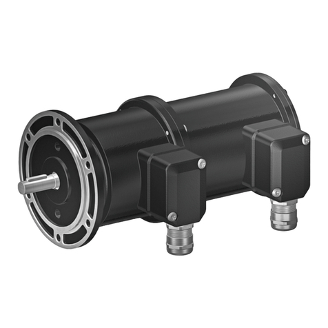
Technische Daten Technical data Données techniques
Erfassungsbereich Sd 0,3 ... 8,5 m sensing distance Sd 0,3 ... 8,5 m Portée de détection Sd 0,3 ... 8,5 m
Ö󰀨nungswinkel 6° (3dB) aperture angle 6° (3dB) Angle d‘ouverture 6° (3dB)
Betriebsspannungsbereich
+Vs
9 ... 32 VDC voltage supply range
+Vs
9 ... 32 VDC Plage de tension +Vs 9 ... 32 VDC
Stromaufnahme max.
(ohne Last)
160 mA current consumption
max. (no load)
160 mA Consommation max.
(sans charge)
160 mA
Ausgangsschaltung CAN (5V) output circuit CAN (5V) circuit de sortie CAN (5V)
logische Schnittstelle CAN SAE J1939 logical interface CAN SAE J1939 interface logique CAN SAE J1939
Baud Rate 250 kBaud (500 kBaud) baud rate 250 kBaud (500 kBaud) vitesse de transmission 250 kBaud (500 kBaud)
kurzschlussfest ja short circuit protection yes Protégé contre
courts-circuits
oui
verpolungsfest ja, Vs zu GND reverse polarity pro-
tection
yes, Vs to GND Protégé contre inversion
polarité
oui, Vs vers GND
Arbeitstemperatur -40 ... +70 °C operating temperature -40 ... +70 °C Température de foncti-
onnement
-40 ... +70 °C
Lagertemperatur -40 ... +85 °C storage temperature -40 ... +85 °C Température de stocka-
ge
-40 ... +85 °C
Schutzart IP 68/69K protection class IP 68/69K Classe de protection IP 68/69K
R600V.RAH5-11225384
Abmessungen Dimensions Dimensions Elektrischer Anschluss Schéma de raccordement
• Alle Masse in mm
• All dimensions in mm
• Toutes les dimensions en mm
• Vor dem Anschliessen des Sensors die Anlage spannungsfrei schalten.
• Disconnect power before connecting the sensor.
• Mettre l`installation hors tension avant le raccordement du détecteur.
Connection diagram
FCC Compliance Statement
This device complies with Part 15 of the FCC Rules. Operation is subject to the following two conditions: (1) this device may not
cause harmful interference, and (2) this device must accept any interference received, including interference that may cause
undesired operation.
NOTICE: Changes or modications made to this equipment not expressly approved by Baumer may void the FCC authorization
to operate this equipment.
NOTE: This equipment has been tested and found to comply with the limits for a Class A digital device, pursuant to Part 15 of
the FCC Rules. These limits are designed to provide reasonable protection against harmful interference when the equipment is
operated in a commercial environment. This equipment generates, uses, and can radiate radio frequency energy and, if not in-
stalled and used in accordance with the instruction manual, may cause harmful interference to radio communications. Operation
of this equipment in a residential area is likely to cause harmful interference in which case the user will be required to correct the
interference at his own expense.
Radiofrequency radiation exposure Information: This equipment complies with FCC exposure limits set forth for an uncontrolled
environment. This equipment should be installed and operated with minimum distance of 20 cm between the radiator and your
body. This transmitter must not be co-located or operating in conjunction with any other antenna or transmitter.
Canada Compliance Statement
This device complies with Industry Canada licence-exempt RSS standard(s). Operation is subject to the following two condi-
tions: (1) this device may not cause harmful interference, and (2) this device must accept any interference received, including
interference that may cause undesired operation. This equipment complies with IC radiation exposure limits set forth for an un-
controlled environment. This equipment should be installed and operated with minimum distance of 20 cm between the radiator
and your body. This transmitter must not be co-located or operating in conjunction with any other antenna or transmitter.
Le présent appareil est conforme aux CNR d‘Industrie Canada applicables aux appareils radio exempts de licence. L‘exploita-
tion est autorisée aux deux conditions suivantes: (1) l‘appareil ne doit pas produire de brouillage, et (2) l‘appareil doit accepter
tout brouillage radioélectrique subi, même si le brouillage est susceptible d‘en compromettre le fonctionnement. Cet équipement
est conforme aux limites d‘exposition aux rayonnements IC établies pour un environnement non contrôlé. Cet équipement doit
être installé et utilisé avec un minimum de 20 cm de distance entre la source de rayonnement et votre corps. Ce transmetteur
ne doit pas etre place au meme endroit ou utilise simultanement avec un autre transmetteur ou antenne.
1/4
Technische Änderungen vorbehalten Tecnical specications subject to change Sous réserve de modications techniques
82
97
84
6,8
2x
17,4
32
62
42 11
42
+Vs
(3)
(1)
(4)
0 V
CAN HI
(2)
CAN SAE
J1939 CAN LO
2 CAN HI
4 CAN LO
1 +Vs
3 GND
Status / Status / Condition Code
Reektor innerhalb der der Toleranz
Reector within tolerance A
Réecteur dans les limites de la tolérance A (Operating range)
100 ms grüne LED an / green LED on / LED verte alluminée
900 ms LED aus / o󰀨 / éteinte
Reektor innerhalb der der Toleranz B
Reector within tolerance B
Réecteur dans les limites de la tolérance B (Boundary range)
2x 50 ms grüne LED an / green LED on / LED verte alluminée
880 ms LED aus / o󰀨 / éteinte
Reektorsignal zu schwach
Reector signal too weak
Signal du réecteur trop faible
3x 50 ms grüne LED an / green LED on / LED verte alluminée
800 ms LED aus / o󰀨 / éteinte
Objekt zwischen Sensor und Reektor
Object between sensor and reector
Objet entre le capteur et le réecteur
wie oben zusätzlich 100 ms gelbe LED an
as above with additional yellow LED on
comme ci-dessus avec supplémentaire LED jaune
Elektronikfehler / Hardware fault / Défaut de matériel 50 ms rote LED an / red LED on / LED rouge alluminée
50 ms LED aus / o󰀨 / éteinte
CAN Abwurf (Fehlfunktion)
CAN bus o󰀨 (malfunction)
Arrêt du bus CAN (dysfonctionnement)
50 ms magenta LED an / on / alluminée
150 ms LED aus / o󰀨 / éteinte
Adresszuweisung fehlgeschlagen
Address claim failed
Assigment d‘ addresse failli
50 ms magenta LED an / on / alluminée
50 ms LED aus / o󰀨 / éteinte
Warten auf Adresszuweisung
Waiting for Master ECU adress claim
En attendre il assignment d‘ adresse du maître ECU
500 ms magenta LED an / on / alluminée
500 ms LED aus / o󰀨 / éteinte
Andere / other / autre blaue LED / blue LED / LED bleue
Grundinformation CAN - basic information CAN -
informations de base CAN
ISO Name
ISO name
Nom ISO
Manufacturer code:
ECU instance:
Function instance:
Function:
System:
System instance:
Industry group:
Arbitration capable:
343 (Baumer Group)
0
4
255 (non specic)
127 (non specic)
0
2
1
Geräteadresse
Device address
Adresse de l‘appareil
Unterstützt / supports „commanded address“ /
supporte adresse commandée (PGN 0xFED8)
im Bereich / in range / dans l‘ interval:
0x80 ... 0xCF (Standard / default / défault 0x80)
SAE J1939 Memory
Access (MA)
Protokoll / protocol /
protocole
Tool Anforderungen / requirements / exigences
- user level = 1
- Key for access is seed from sensor
- direct spatial addresses (is pointer)
- r/w command memory length = 1
- use transfer length from proceed reply
- ISO name Function eld = 129
- ISO name Industry group eld = 0
Objektdetektion und Zähler – object detection and counter – détection et comptage d‘objets
PGN CAN Nachricht / CAN message / Message CAN : 0xC000
Start
bit
Bits Abstand
o󰀨set
décaillage
Skalierung
scaling
écaillage
Beschreibung / description / description
1 2 0 1 Sensorstatus / Sensor status / état de capteur
0 = Kein Fehler / no error / Pas d‘ erreur
1 = Reversibler Fehler / reversible error / erreur reversible
2 = Irreversibler Fehler / irreversible error / erreur irréversible
3 3 0 1 Sensorstatus nach Teach / sensor status after reector teach / état du capteur après Teach du reecteur
0 = Kein Fehler / no error / pas d‘erreur
1 = Signal zu schwach / signal too weak / signal trop faible
2 = Reektor ausserhalb Gültigkeitsbereich / reector outside valid range / Réecteur en dehors de la plage valable
1,2 = Teach nicht akzeptiert / teach not accepted / Teach non accepté
6 1 0 1 Status Objektdetektion / Object detection status / État de la détection des objets
0 = Kein Objekt zwischen Sensor und Reektor / No object between sensor and reector /
Aucun objet entre le capteur et le réecteur
1 = Objekt zwischen Sensor und Reektor / object between sensor and reector / Objet entre le capteur et le réecteur
7 2 0 1 Reektorpositoin / Reector position / Position du réecteur
0 = Reektor im Betriebsbereich (A) / Reector in operating range (A) / Réecteur en zone fonctionnement
1 = Reektor im Grenzbereich (B) / Reector in boundary range (B) / Réecteur en zone limite
2 = Reektor ausserhalb Bereich (A/B) / Reector outside of range (A/B) / Réecteur en dehors de la plage valable
3 =Reektorsignal zu schwach / Reector signal too weak / Le signal du réecteur est trop faible
9 32 0 1 Zähler für Objektdetektionsereignisse / Counter for object detection events / Compteur d‘événements de détection
d‘objets : 0…4’294’967’296
41 12 0 1 N/A
Reflector
e. g. fixed
machine part
Operating range
LED green
flashing
Boundary range
LED green
flashing (fast)
Reflector position R
B
A
Reektorposition R setzen
Set reector position R
Régler la position du réecteur R
(SAE J1939 Memory Access)
Reektordistanz in mm an Adresse schreiben 0x07E388
Write reector distance in to address 0x07E388
Inscrivez la distance du réecteur en mm à l‘adresse
0x07E388
Teach Reektorposition R
Teach reector position R
Teach du reecteur R
(SAE J1939 Memory Access)
Wert 1 auf Adresse 0x07E389 schreiben
Write value 1 to address 0x07E389
Inscrivez la valeur 1 à l‘adresse 0x07E389
2/4
Visuelle Diagnose - Visual diagnostic - Diagnostic visuel
CAN Kommunikation - CAN communication - communication CAN
Für weitere Informationen lesen Sie bitte die Bedienungsanleitung - For further information please refer to the user manual - Pour plus d‘ informations, veuillez vous référer au manuel d‘ utilisation
Reektorposition - Reector Position - Position du réecteur
1 2 3 4 5 6 7 8
F
E
D
C
B
A
ModMod
Rev Drawn Approved Rev Drawn Approved
deburred
Qty Item Pos. Material Remarks
Project
Replaced by
Replacement for
This drawing is OUR PROPERTY and may
not be copied, recreated or made available
to any third party without prior permission
Baumer Electric AG
Postfach · Hummelstrasse 17 · CH-8501 Frauenfeld
Phone +41 (0)52 728 11 22 · Fax +41 (0)52 728 11 44
Drawn
Checked
Approved
Scale
R600V.DAH5-11225384
Radar retro-reflective sensor
11225384 A
10714028 Off Highway
Radar
a 13.01.2021 cg 13.01.2021 rma
RZ.00020
cg09.03.2020
rma09.03.2020
wemi09.03.2020
1:1
13. Jan. 2021 11:50
2
3
1
4
Mating Connector
AMPSEAL 16
776524-1
PIN 1 +Vs
PIN 2 CAN HI
PIN 3 GND
PIN 4 CAN LO
82 ±0,3
62 ±0,5
97 ±0,5
17,4 ±0,5
60°
center axis
42,5 ±0,5
32 ±0,5
84 ±0,5
R600V.DAH5-11xxxxxx
11xxxxxx
SN: xxxx.10.X-xxxx-xxxx
FCC ID: xxxxxx IC ID: xxxxxx HVIN: xxxxxx
Laser marked
6,8±0,2
20max. O
11 ±0,5 18,5
42 ±0,5
42 ±0,5 (Lens)
zero distance
NOTES:
1. ELECTRICAL SPECIFICATION:
a. VOLTAGE SUPPLY RANGE: 9V…32V (12VDC/24VDC VEHICLE POWER)
b. CURRENT CONSUMPTION: <160mA (averaged)
c. RADAR FREQUENCY: 122GHz…123GHz
2. OUTPUT FUNCTION:
a. CAN SAE J1939
b. BAUD RATE: 250/500kbaud
c. OUTPUT CIRCUIT: CAN 5V without internal 120Ω terminator
d. CAN UPDATE RATE: ≥ 0.2Hz … ≤ 100 Hz
e. SENSING RANGE: 300mm…8500mm (center axis)
f. REFLECTOR POSITION RANGE: 300mm…8500mm (center axis)
g. BLIND RANGE: 300mm
3. MECHANICAL DATA:
a. RECTANGULAR HOUSING: 97 x 84 x 42.5mm (without connector)
b. DIAMETER MOUNTING HOLES:6.8mm±0.2mm
c. RECOMMENDED SCREWS: M6 ACC. MBM 10105
d. INSTALLATION TORQUE: Screw with property class 10.9: max torque of screw
12Nm…15Nm, Screw with property class 8.8: max torque of screw 10Nm…12Nm
e. ENCLOSURE MATERIAL: POLYAMID (GLASS FIBRE REINFORCED)
f. MOUNTING PLATE: ALUMINUM (COATED WITH CATAPHORETIC PAINTING (KTL))
g. LENS MATERIAL: Polyetherimid (PEI)
4. AMBIENT CONDITIONS:
a. STORAGE TEMPERATURE: -40°C…+85°C
b. OPERATING TEMPERATURE: -40°C…+70°C
5. SENSOR MEETS FOLLOWING REQUIREMENTS OF EMC AND ENVIRONMENT ACC. FSP:
a. EMC AGRICULTURAL MACHINERY EN ISO 14982 (12V/24V-SYSTEM)
b. EMC CONSTRUCTION MACHINERY EN 13309 (12V/24V-SYSTEM)
c. EMC EARTH MOVING MACHINERY ISO 13766 (12V/24V-SYSTEM)
d. EUROPE: RADIO EQUIPMENT AND REPEALING DIRECTIVE (RED) 2014/53/EU
e. USA / CDN: COMPLIANCE STATEMENTS SEE PAGE 2, CHAPTER 11 OF THIS
DRAWING
f. EMC (CE) EN 61000-6-2 / EN 61000-6-3
g. PROTECTION CLASS ISO 20653_2013: IP68/IP69K
h. PARTICLE IMPACT EN ISO 20567-1 (GRAVEL EN11124-2)
i. RANDOM VIBRATION IEC 60068-2-64 (5Hz…2000Hz, 11.55 Grms)
j. OPERATING MECHANICAL SHOCK IEC 60068-2-27 (50g)
6. PART IS MARKED WITH BAUMER LOGO; PART NUMBER; DATE CODE, SERIAL NUMBER
7. MOUNTING RECOMMENDATION:
a. REQUIRED FLATNESS OF THE SENSOR MOUNTING SURFACE ≤0.2mm/100mm
b. DIRECT MOUNTING ONTO A STEEL PLATE WITH A THICKNESS OF 6mm WITH TWO M6 SCREWS
c. INDIRECT MOUNTING ONTO A STEEL PLATE WITH A THICKNESS OF 3mm WITH T
WO M6 SCREWS AND
TWO FLANGE NUTS
8. LED FUNCTIONS (LED INSIDE LENS)
a. SENSOR FULLY OPERATIONAL (Reflector in Operating Range A): GREEN LED blinking
b. SENSOR FULLY OPERATIONAL (Reflector in Boundary Range B): GREEN/Yellow LED blinking
c. NO REFLECTOR OR SWITCHING DETECTED: GREEN / YELLOW 2x blinking
d. CAN BUS WAITING ON MASTER OR ERRORS: MAGENTA LED blinking
e. HW FAULT: RED LED blinking
9. Intended use / application policy:
a. The suitability and functionality of a Baumer product and its performance under different applications and / or end-
use cases can only be verified by testing, and shall ultimately be the responsibility of the customer.
b. The product shall not be used:
- For functional safety applications and in potentially explosive atmospheres.
- In the direct control and modification of the state of function of the machine.
c. Possible malfunctions and failed measurements of the sensor must be intercepted at the system level and shall not
lead to unsafe situations in the system.
d. The customer shall perform its own safety assessment to account for sensor behavior in particular situations (e.g.
distance fluctuations in static situations, operator caused distance manipulation by hand or other objects).
e. Safety relevant information must be communicated to the end-user.
10. Recommended free space around radar lens:
Rotational cone with an angle of ± 30° around sensor center axis
Sensitivity and detection of objects near the dead band can be influenced by disturbing objects (e.g. metal boom
structures or water hose) within this free space. Moving objects up to 60° outside of free space should be avoided.
Further testing is recommended to define a smaller free space.
1 / 2
3/4
1 2 3 4 5 6 7 8
F
E
D
C
B
A
ModMod
Rev Drawn Approved Rev Drawn Approved
deburred
Qty Item Pos. Material Remarks
Project
Replaced by
Replacement for
This drawing is OUR PROPERTY and may
not be copied, recreated or made available
to any third party without prior permission
Baumer Electric AG
Postfach · Hummelstrasse 17 · CH-8501 Frauenfeld
Phone +41 (0)52 728 11 22 · Fax +41 (0)52 728 11 44
Drawn
Checked
Approved
Scale
R600V.DAH5-11225384
Radar retro-reflective sensor
11225384 A
10714028 Off Highway
Radar
a 13.01.2021 cg 13.01.2021 rma
RZ.00020
cg09.03.2020
rma09.03.2020
wemi09.03.2020
1:1
13. Jan. 2021 11:50
2 / 2
11. Compliance Statements:
a. FCC Compliance Statement
This device complies with Part 15 of the FCC Rules.
Operation is subject to the following two conditions:
(1) this device may not cause harmful interference, and
(2) this device must accept any interference received, including interference that may cause
undesired operation.
NOTICE: Changes or modifications made to this equipment not expressly approved by
Baumer may void the FCC authorization to operate this equipment.
NOTE: This equipment has been tested and found to comply with the limits for a Class A
digital device, pursuant to Part 15 of the FCC Rules. These limits are designed to provide
reasonable protection against harmful interference when the equipment is operated in a
commercial environment. This equipment generates, uses, and can radiate radio frequency
energy and, if not installed and used in accordance with the instruction manual, may cau se
harmful interference to radio communications. Operation of this equipment in a residential
area is likely to cause harmful interference in which case the user will be required to correct
the interference at his own expense.
Radiofrequency radiation exposure Information:
This equipment complies with FCC exposure limits set forth for an uncontrolled environment.
This equipment should be installed and operated with minimum distance of 20 cm between
the radiator and your body.
This transmitter must not be co-located or operating in conjunction with any other antenna or
transmitter.
b. Canada Compliance Statement
This device complies with Industry Canada licence-exempt RSS standard(s).
Operation is subject to the following two conditions:
(1) this device may not cause harmful interference, and
(2) this device must accept any interference received, including interference that may cause
undesired operation.
This equipment complies with IC radiation exposure limits set forth for an uncontrolled
environment. This equipment should be installed and operated with minimum distance of 20
cm between the radiator and your body.
This transmitter must not be co-located or operating in conjunction with any other antenna or
transmitter.
Le présent appareil est conforme aux CNR d'Industrie Canada applicables aux appareils
radio exempts de licence. L'exploitation est autorisée aux deux conditions suivantes:
(1) l'appareil ne doit pas produire de brouillage, et
(2) l'appareil doit accepter tout brouillage radioélectrique subi, même si le brouillage est
susceptible d'en compromettre le fonctionnement.
Cet équipement est conforme aux limites d'exposition aux rayonnements IC établies pour un
environnement non contrôlé. Cet équipement doit être installé et utilisé avec un minimum de
20 cm de distance entre la source de rayonnement et votre corps.
Ce transmetteur ne doit pas être place au même endroit ou utilise simultanément avec un
autre transmetteur ou antenne.
4/4

Other Baumer Measuring Instrument manuals

Baumer MCD7 Manual

Baumer

Baumer MCD7 Manual

Baumer PAC50H User manual

Baumer

Baumer PAC50H User manual

Baumer CTX User manual

Baumer

Baumer CTX User manual

Baumer OM20 User manual

Baumer

Baumer OM20 User manual

Baumer TA202 User manual

Baumer

Baumer TA202 User manual

Baumer GCA5 C8 User manual

Baumer

Baumer GCA5 C8 User manual

Baumer TA200 User manual

Baumer

Baumer TA200 User manual

Baumer EAM500 User manual

Baumer

Baumer EAM500 User manual

Baumer TER8 User manual

Baumer

Baumer TER8 User manual

Baumer OPDK 14N5901/S35A User manual

Baumer

Baumer OPDK 14N5901/S35A User manual

Baumer N 208 User manual

Baumer

Baumer N 208 User manual

Baumer TA201 User manual

Baumer

Baumer TA201 User manual

Baumer CleverLevel LBFH/I User manual

Baumer

Baumer CleverLevel LBFH/I User manual

Baumer CombiLyz AFI4 User manual

Baumer

Baumer CombiLyz AFI4 User manual

Baumer isiLine 36 User manual

Baumer

Baumer isiLine 36 User manual

Baumer FKDM 22P1901/S14F User manual

Baumer

Baumer FKDM 22P1901/S14F User manual

Baumer CleverLevel PL20H/S User manual

Baumer

Baumer CleverLevel PL20H/S User manual

Baumer GT5.05L/407 User manual

Baumer

Baumer GT5.05L/407 User manual

Baumer OM20 User manual

Baumer

Baumer OM20 User manual

Baumer 11042576 Service manual

Baumer

Baumer 11042576 Service manual

Baumer TDP 0,2+OG 9 User manual

Baumer

Baumer TDP 0,2+OG 9 User manual

Baumer Hubner HENQ 1100 User manual

Baumer

Baumer Hubner HENQ 1100 User manual

Baumer HUBNER POG 10 + ESL Service manual

Baumer

Baumer HUBNER POG 10 + ESL Service manual

Baumer VCXG.2-13M User manual

Baumer

Baumer VCXG.2-13M User manual

Popular Measuring Instrument manuals by other brands

Armada Technologies Pro50K instruction manual

Armada Technologies

Armada Technologies Pro50K instruction manual

HBM C16i series installation instructions

HBM

HBM C16i series installation instructions

Dwyer Instruments Series 2-5000 Minihelic II Specifications-installation and operating instructions

Dwyer Instruments

Dwyer Instruments Series 2-5000 Minihelic II Specifications-installation and operating instructions

GDS 301 Operating handbook

GDS

GDS 301 Operating handbook

TempSen ITAG 3 Series quick guide

TempSen

TempSen ITAG 3 Series quick guide

Interface BlueDAQ BX8 quick start guide

Interface

Interface BlueDAQ BX8 quick start guide

Sierra InnovaSonic 210 instruction manual

Sierra

Sierra InnovaSonic 210 instruction manual

Interface GOLD STANDARD manual

Interface

Interface GOLD STANDARD manual

MAC MULTI-MATIC Assembly instructions

MAC

MAC MULTI-MATIC Assembly instructions

Novalynx 255-110-B Series user manual

Novalynx

Novalynx 255-110-B Series user manual

Tektronix PA3000 Installation & safety guide

Tektronix

Tektronix PA3000 Installation & safety guide

JENCO 6250 Operation manual

JENCO

JENCO 6250 Operation manual

GW Instek GDP-040D quick start guide

GW Instek

GW Instek GDP-040D quick start guide

WilTec 51487 Operation manual

WilTec

WilTec 51487 Operation manual

Tektronix RSA306B instructions

Tektronix

Tektronix RSA306B instructions

Mindray BC-2800 Operation manual

Mindray

Mindray BC-2800 Operation manual

VOLTCRAFT CO-700 operating instructions

VOLTCRAFT

VOLTCRAFT CO-700 operating instructions

Textron Greenlee 570XL Series instruction manual

Textron

Textron Greenlee 570XL Series instruction manual

manuals.online logo
manuals.online logoBrands
  • About & Mission
  • Contact us
  • Privacy Policy
  • Terms and Conditions

Copyright 2025 Manuals.Online. All Rights Reserved.