TABLE OF CONTENTS
MB168T1EN - 11184527, 19A2, Baumer_HMC16-T1_II_EN
6. ELECTRICAL CONNECTION..............................................................................................12
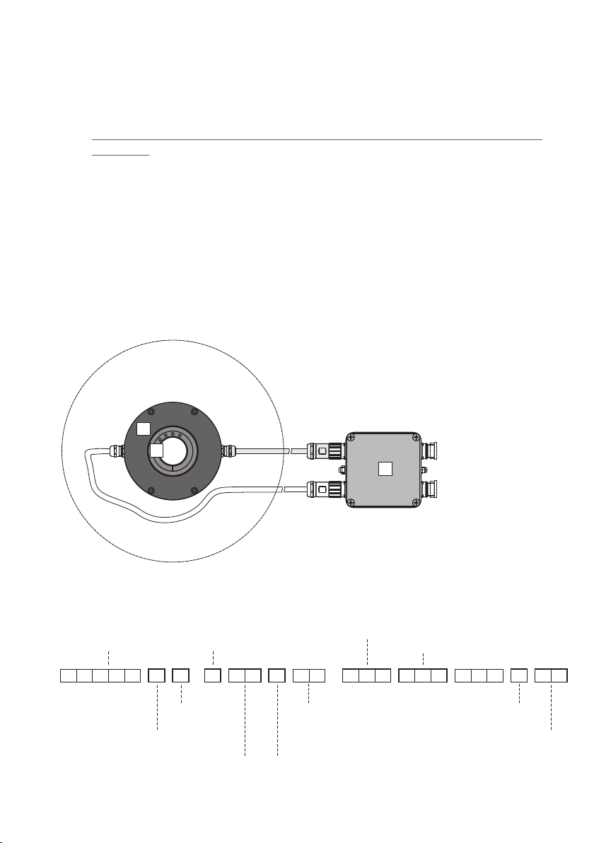
6.1 Functional principle HMCP16 .......................................................................................12
6.2 PartnumberdenitionHMCP16...................................................................................13
6.2.1 Overview .........................................................................................................13
6.2.2 Table „Output“ .................................................................................................13
6.2.3 Table „Pulses (periods)“ ..................................................................................14
6.2.4 Table „Frequency output“ ................................................................................14
6.2.5 Table „Power supply“ ......................................................................................14
6.2.6 Table„Envelopedelaytimeofthelterinµs“ .................................................14
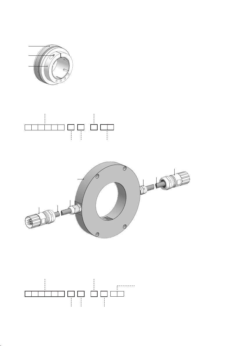
6.3 Connecting HMCP16 to HMCK16 ................................................................................15
6.4 Terminalsignicance ....................................................................................................15
6.5 Pin assignment mating connector HMCK16.................................................................16
6.6 Connecting overview signal processing electronic HMCP16 .......................................16
6.7 Inputs HMCP16 ............................................................................................................17
6.7.1 Input 1 (and 2): SinCos ...................................................................................17
6.8 Outputs HMCP16 .........................................................................................................17
6.8.1 Output signals depending on the version........................................................17
6.8.1.1 SinCos ..................................................................................................17
6.8.1.2 HTL, TTL, Universal..............................................................................17
6.8.1.3 SSI telegram .........................................................................................18
6.8.1.4 Frequency output..................................................................................18
6.8.2 Connection assignment ..................................................................................19
6.8.2.1 Output 1 „S“: SinCos 1 VSS ...................................................................19
6.8.2.2 Output 1 „A“: SinCos 1 VSS + error output TTL level .............................19
6.8.2.3 Output 1 (or 2) „H“ or „T“: HTL or TTL...................................................20
6.8.2.4 Output 1 (or 2) „U“: Universal HTL/TTL ................................................20
6.8.2.5 Output 1 (or 2) „B“: TTL + error output TTL level ..................................21
6.8.2.6 Output 1 (or 2) „C“: HTL + error output HTL level.................................21
6.8.2.7 Output 1 (or 2) „P“: Universal HTL/TTL + error output TTL level ..........22
6.8.2.8 Output 1 (or 2) „M“: 2x SSI .................................................................22
6.8.2.9 Output 1 (or 2) „F“: TTL frequency output.............................................23
6.9 Connection assignment external power supply „E“ HMCP16.......................................23