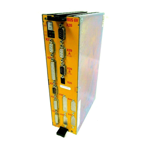
Baumuller b maXX BM5800 User manual

Parameter manual
Read the Operating Manual before starting any work!
Language English
Translation
Document No. 5.16029.03
Part No. 00470716
Status 30.07.2019
b maXX BM5800
Multi-axis controller
Parameter manual
Version 01.15
E5.16029.03

Copyright The owner may produce an unrestricted number of copies of this Parameter manual solely
for internal use. This Parameter manual may not be copied or reproduced, even in extract
form, for any other purpose.
Use and disclosure of the contents of this Parameter manual are not permitted.
Names or company symbols in this Parameter manual can be trademarks, the use of which
by third parties for their own purposes may infringe the rights of the owners.
Preliminary informationCaution: The following applies if this document is identified as preliminary information:
This version contains preliminary technical information which the users of the devices and
functions described are intended to receive in advance, in order to be able to make arrange-
ments for any changes or functional enhancements that may be required.
This information should be considered to be provisional, as it has not yet been subjected to
the final Baumüller internal review process. In particular this information is still subject to
change, so that no legal obligation can be deduced on the basis of this preliminary informa-
tion. Baumüller accepts no liability for damages that may arise from this possibly erroneous
or incomplete version.
Should you detect or suspect errors of content and/or serious technical errors in this prelim-
inary information, we ask you to contact the Baumüller support person responsible for you
and inform us of your findings and comments so that they might be considered and possibly
incorporated when the preliminary information becomes finalized (reviewed by Baumüller).
The conditions noted in the following section under "Liability" do not apply in the case of pre-
liminary information.
Obligation This Parameter manual is a part of the device/machine. This Parameter manual must be ac-
cessible to the operator at all times and be in a legible condition. When the device/machine
is sold/relocated, this Parameter manual must be passed on together with the device/ma-
chine by the owner.
After the device/machine is sold, this original and all copies must be handed over to the pur-
chaser. After disposal or other end of service life, this original and all copies must be de-
stroyed.
When this Parameter manual is handed over, the corresponding Operating Manuals with ear-
lier issue dates become invalid.
Please note that specifications/data/information arethecurrent values on the date of print-
ing. These specifications are not legally binding for measuring, computation and costing.
Baumüller Nürnberg GmbH reserves the right to change the technical data and operation of
Baumüller products within the framework of its own further development of the products.
However no guarantee can be provided regarding the freedom from errors of this Parameter
manual, unless otherwise described in the General Conditions for Sales and Supply.
Baumüller Nürnberg GmbH
Ostendstr. 80 - 90
90482 Nürnberg
Germany
Tel. +49 9 11 54 32 - 0
Fax: +49 9 11 54 32 - 1 30
Internet: www.baumueller.de

Parameter manual b maXX BM5800
Document No.: 5.16029.03 3
of 814
Table of Contents
1 General . . . . . . . . . . . . . . . . . . . . . . . . . . . . . . . . . . . . . . . . . . . . . . . . . . . . . . . . . . . . . . . . . 11
1.1 Information about the Parameter Manual . . . . . . . . . . . . . . . . . . . . . . . . . . . . . . . . . . 11
1.2 Explanation of Symbols . . . . . . . . . . . . . . . . . . . . . . . . . . . . . . . . . . . . . . . . . . . . . . . . 12
1.3 Limitation of Liability . . . . . . . . . . . . . . . . . . . . . . . . . . . . . . . . . . . . . . . . . . . . . . . . . . 13
1.4 Copyright . . . . . . . . . . . . . . . . . . . . . . . . . . . . . . . . . . . . . . . . . . . . . . . . . . . . . . . . . . . 13
1.5 Other Applicable Documents. . . . . . . . . . . . . . . . . . . . . . . . . . . . . . . . . . . . . . . . . . . . 14
1.6 Guarantee Conditions . . . . . . . . . . . . . . . . . . . . . . . . . . . . . . . . . . . . . . . . . . . . . . . . . 14
1.7 Customer service. . . . . . . . . . . . . . . . . . . . . . . . . . . . . . . . . . . . . . . . . . . . . . . . . . . . . 14
1.8 Terms used . . . . . . . . . . . . . . . . . . . . . . . . . . . . . . . . . . . . . . . . . . . . . . . . . . . . . . . . . 14
2 Commissioning . . . . . . . . . . . . . . . . . . . . . . . . . . . . . . . . . . . . . . . . . . . . . . . . . . . . . . . . . . 15
2.1 Safety information . . . . . . . . . . . . . . . . . . . . . . . . . . . . . . . . . . . . . . . . . . . . . . . . . . . . 16
2.2 Voltage test . . . . . . . . . . . . . . . . . . . . . . . . . . . . . . . . . . . . . . . . . . . . . . . . . . . . . . . . . 17
2.3 Requirements for the electrical supply. . . . . . . . . . . . . . . . . . . . . . . . . . . . . . . . . . . . . 18
2.4 Preparations . . . . . . . . . . . . . . . . . . . . . . . . . . . . . . . . . . . . . . . . . . . . . . . . . . . . . . . . 18
2.4.1 Communication via EtherCAT. . . . . . . . . . . . . . . . . . . . . . . . . . . . . . . . . . . . . . . . . . 20
2.5 Switch-on sequence . . . . . . . . . . . . . . . . . . . . . . . . . . . . . . . . . . . . . . . . . . . . . . . . . . 26
2.6 Performing the commissioning (using Axis 1 as an example). . . . . . . . . . . . . . . . . . . 27
3 Description of the Software Modules and Parameters. . . . . . . . . . . . . . . . . . . . . . . . . . . 47
3.1 Cycle times of the software modules. . . . . . . . . . . . . . . . . . . . . . . . . . . . . . . . . . . . . . 47
3.1.1 Cycle times at axis units . . . . . . . . . . . . . . . . . . . . . . . . . . . . . . . . . . . . . . . . . . . . . . 47
3.2 Structure of the parameter overviews . . . . . . . . . . . . . . . . . . . . . . . . . . . . . . . . . . . . . 49
3.3 System. . . . . . . . . . . . . . . . . . . . . . . . . . . . . . . . . . . . . . . . . . . . . . . . . . . . . . . . . . . . . 51
3.3.1 System control. . . . . . . . . . . . . . . . . . . . . . . . . . . . . . . . . . . . . . . . . . . . . . . . . . . . . . 51
3.3.1.1 Parameter overview. . . . . . . . . . . . . . . . . . . . . . . . . . . . . . . . . . . . . . . . . . . . . . . . . 51
3.3.1.2 Description of the Parameters. . . . . . . . . . . . . . . . . . . . . . . . . . . . . . . . . . . . . . . . . 52
3.4 Configuration . . . . . . . . . . . . . . . . . . . . . . . . . . . . . . . . . . . . . . . . . . . . . . . . . . . . . . . . 61
3.4.1 Power unit . . . . . . . . . . . . . . . . . . . . . . . . . . . . . . . . . . . . . . . . . . . . . . . . . . . . . . . . . 61
3.4.1.1 ProDrive Power Unit . . . . . . . . . . . . . . . . . . . . . . . . . . . . . . . . . . . . . . . . . . . . . . . . 62
3.4.1.2 Parameter overview. . . . . . . . . . . . . . . . . . . . . . . . . . . . . . . . . . . . . . . . . . . . . . . . . 62
3.4.1.3 Description of the Parameters. . . . . . . . . . . . . . . . . . . . . . . . . . . . . . . . . . . . . . . . . 64
3.4.2 Motor. . . . . . . . . . . . . . . . . . . . . . . . . . . . . . . . . . . . . . . . . . . . . . . . . . . . . . . . . . . . . 81
3.4.2.1 Motor Identification Plate. . . . . . . . . . . . . . . . . . . . . . . . . . . . . . . . . . . . . . . . . . . . . 81
3.4.2.2 Torque limits . . . . . . . . . . . . . . . . . . . . . . . . . . . . . . . . . . . . . . . . . . . . . . . . . . . . . . 81
3.4.2.3 Torque monitoring . . . . . . . . . . . . . . . . . . . . . . . . . . . . . . . . . . . . . . . . . . . . . . . . . . 83
3.4.2.4 Torque threshold . . . . . . . . . . . . . . . . . . . . . . . . . . . . . . . . . . . . . . . . . . . . . . . . . . . 83
3.4.2.5 Maximum permissible speed (electrical conditioned) . . . . . . . . . . . . . . . . . . . . . . . 84
3.4.2.6 ProDrive Motor. . . . . . . . . . . . . . . . . . . . . . . . . . . . . . . . . . . . . . . . . . . . . . . . . . . . . 85
3.4.2.7 Parameter overview motor. . . . . . . . . . . . . . . . . . . . . . . . . . . . . . . . . . . . . . . . . . . . 85
3.4.2.8 Description of the Parameters. . . . . . . . . . . . . . . . . . . . . . . . . . . . . . . . . . . . . . . . . 89
3.4.3 Synchronous Motor. . . . . . . . . . . . . . . . . . . . . . . . . . . . . . . . . . . . . . . . . . . . . . . . . 120
3.4.3.1 ProDrive Synchronous Motor. . . . . . . . . . . . . . . . . . . . . . . . . . . . . . . . . . . . . . . . . 120
3.4.3.2 Torque ripple compensation . . . . . . . . . . . . . . . . . . . . . . . . . . . . . . . . . . . . . . . . . 120
3.4.4 Asynchronous Motor . . . . . . . . . . . . . . . . . . . . . . . . . . . . . . . . . . . . . . . . . . . . . . . . 123
3.4.4.1 ProDrive Asynchronous Motor. . . . . . . . . . . . . . . . . . . . . . . . . . . . . . . . . . . . . . . . 123
3.4.4.2 Lh-characteristic . . . . . . . . . . . . . . . . . . . . . . . . . . . . . . . . . . . . . . . . . . . . . . . . . . 123
3.4.4.3 ProDrive Lh-characteristic . . . . . . . . . . . . . . . . . . . . . . . . . . . . . . . . . . . . . . . . . . . 125
3.4.4.4 Parameter overview Lh-characteristic . . . . . . . . . . . . . . . . . . . . . . . . . . . . . . . . . . 126

Parameter manual b maXX BM5800
Document No.: 5.16029.03 Baumüller Nürnberg GmbH
4
of 814
Contents
3.4.4.5 Description of the Lh-characteristic parameters. . . . . . . . . . . . . . . . . . . . . . . . . . . 126
3.4.5 Synchronous motor with interior permanent magnet. . . . . . . . . . . . . . . . . . . . . . . . 128
3.4.5.1 Control . . . . . . . . . . . . . . . . . . . . . . . . . . . . . . . . . . . . . . . . . . . . . . . . . . . . . . . . . . 128
3.4.5.2 Commissioning. . . . . . . . . . . . . . . . . . . . . . . . . . . . . . . . . . . . . . . . . . . . . . . . . . . . 129
3.4.5.3 Identification of the nonlinear parameters . . . . . . . . . . . . . . . . . . . . . . . . . . . . . . . 130
3.4.5.4 Field weakening at IPMSM. . . . . . . . . . . . . . . . . . . . . . . . . . . . . . . . . . . . . . . . . . . 130
3.4.5.5 Torque ripple compensation at IPMSM . . . . . . . . . . . . . . . . . . . . . . . . . . . . . . . . . 133
3.4.5.6 Parameter overview . . . . . . . . . . . . . . . . . . . . . . . . . . . . . . . . . . . . . . . . . . . . . . . . 133
3.4.5.7 Description of the parameter . . . . . . . . . . . . . . . . . . . . . . . . . . . . . . . . . . . . . . . . . 134
3.4.6 Encoder . . . . . . . . . . . . . . . . . . . . . . . . . . . . . . . . . . . . . . . . . . . . . . . . . . . . . . . . . . 138
3.4.6.1 Length measuring devices . . . . . . . . . . . . . . . . . . . . . . . . . . . . . . . . . . . . . . . . . . . 139
3.4.6.2 Encoder monitoring . . . . . . . . . . . . . . . . . . . . . . . . . . . . . . . . . . . . . . . . . . . . . . . . 140
3.4.6.3 ProDrive Encoder. . . . . . . . . . . . . . . . . . . . . . . . . . . . . . . . . . . . . . . . . . . . . . . . . . 144
3.4.6.4 Encoder optimization . . . . . . . . . . . . . . . . . . . . . . . . . . . . . . . . . . . . . . . . . . . . . . . 144
3.4.6.5 Encoder correction. . . . . . . . . . . . . . . . . . . . . . . . . . . . . . . . . . . . . . . . . . . . . . . . . 145
3.4.6.6 Encoder accuracy and excentricity. . . . . . . . . . . . . . . . . . . . . . . . . . . . . . . . . . . . . 148
3.4.6.7 SSI digital configuration . . . . . . . . . . . . . . . . . . . . . . . . . . . . . . . . . . . . . . . . . . . . . 149
3.4.6.8 Resolver synchronization. . . . . . . . . . . . . . . . . . . . . . . . . . . . . . . . . . . . . . . . . . . . 150
3.4.6.9 Encoder angle via fieldbus. . . . . . . . . . . . . . . . . . . . . . . . . . . . . . . . . . . . . . . . . . . 151
3.4.6.10 Parameter overview . . . . . . . . . . . . . . . . . . . . . . . . . . . . . . . . . . . . . . . . . . . . . . . . 152
3.4.6.11 Description of the Parameters . . . . . . . . . . . . . . . . . . . . . . . . . . . . . . . . . . . . . . . . 155
3.4.7 Autotuning of Current Controller . . . . . . . . . . . . . . . . . . . . . . . . . . . . . . . . . . . . . . . 181
3.4.7.1 ProDrive Autotuning of the Current Controller . . . . . . . . . . . . . . . . . . . . . . . . . . . . 182
3.4.7.2 Parameter overview Autotuning of the Current Controller . . . . . . . . . . . . . . . . . . . 182
3.4.7.3 Description of the Parameters . . . . . . . . . . . . . . . . . . . . . . . . . . . . . . . . . . . . . . . . 183
3.4.8 Autotuning of position / speed controller . . . . . . . . . . . . . . . . . . . . . . . . . . . . . . . . . 189
3.4.8.1 Ks Determination . . . . . . . . . . . . . . . . . . . . . . . . . . . . . . . . . . . . . . . . . . . . . . . . . . 189
3.4.8.2 ProDrive Ks Determination. . . . . . . . . . . . . . . . . . . . . . . . . . . . . . . . . . . . . . . . . . . 193
3.4.8.3 Parameter overview Ks measurement. . . . . . . . . . . . . . . . . . . . . . . . . . . . . . . . . . 193
3.4.8.4 Description of the Ks measurement parameters . . . . . . . . . . . . . . . . . . . . . . . . . . 194
3.4.8.5 Control loop analysis . . . . . . . . . . . . . . . . . . . . . . . . . . . . . . . . . . . . . . . . . . . . . . . 198
3.4.9 Autotuning Asynchronous Motor . . . . . . . . . . . . . . . . . . . . . . . . . . . . . . . . . . . . . . . 202
3.4.9.1 Identification Lh-characteristic . . . . . . . . . . . . . . . . . . . . . . . . . . . . . . . . . . . . . . . . 202
3.4.10 Digital Inputs . . . . . . . . . . . . . . . . . . . . . . . . . . . . . . . . . . . . . . . . . . . . . . . . . . . . . . 203
3.4.10.1 Digital inputs at axis units. . . . . . . . . . . . . . . . . . . . . . . . . . . . . . . . . . . . . . . . . . . . 203
3.4.10.2 Parameter overview . . . . . . . . . . . . . . . . . . . . . . . . . . . . . . . . . . . . . . . . . . . . . . . . 203
3.4.10.3 Description of the Parameters . . . . . . . . . . . . . . . . . . . . . . . . . . . . . . . . . . . . . . . . 204
3.4.11 Fieldbus communication . . . . . . . . . . . . . . . . . . . . . . . . . . . . . . . . . . . . . . . . . . . . . 207
3.4.11.1 Parameter Ids for the Real Time Lists . . . . . . . . . . . . . . . . . . . . . . . . . . . . . . . . . . 210
3.4.11.2 Access Counter for each Real Time List . . . . . . . . . . . . . . . . . . . . . . . . . . . . . . . . 210
3.4.11.3 Parameter overview . . . . . . . . . . . . . . . . . . . . . . . . . . . . . . . . . . . . . . . . . . . . . . . . 210
3.4.11.4 Description of the Parameters . . . . . . . . . . . . . . . . . . . . . . . . . . . . . . . . . . . . . . . . 211
3.4.12 Measuring encoder function . . . . . . . . . . . . . . . . . . . . . . . . . . . . . . . . . . . . . . . . . . 220
3.4.12.1 ProDrive Measuring Encoder. . . . . . . . . . . . . . . . . . . . . . . . . . . . . . . . . . . . . . . . . 222
3.4.12.2 Parameter overview . . . . . . . . . . . . . . . . . . . . . . . . . . . . . . . . . . . . . . . . . . . . . . . . 222
3.4.12.3 Description of the Parameter . . . . . . . . . . . . . . . . . . . . . . . . . . . . . . . . . . . . . . . . . 224
3.4.13 Customizable PID controller . . . . . . . . . . . . . . . . . . . . . . . . . . . . . . . . . . . . . . . . . . 240
3.4.13.1 Parameter overview . . . . . . . . . . . . . . . . . . . . . . . . . . . . . . . . . . . . . . . . . . . . . . . . 241
3.4.13.2 Description of the Parameters . . . . . . . . . . . . . . . . . . . . . . . . . . . . . . . . . . . . . . . . 243
3.4.14 PT1Filters . . . . . . . . . . . . . . . . . . . . . . . . . . . . . . . . . . . . . . . . . . . . . . . . . . . . . . . . 251
3.4.14.1 Temporal features of the filters. . . . . . . . . . . . . . . . . . . . . . . . . . . . . . . . . . . . . . . . 251
3.4.14.2 Parameter overview . . . . . . . . . . . . . . . . . . . . . . . . . . . . . . . . . . . . . . . . . . . . . . . . 251
3.4.14.3 Description of the Parameters . . . . . . . . . . . . . . . . . . . . . . . . . . . . . . . . . . . . . . . . 252
3.4.15 Master-Slave Torque Coupling . . . . . . . . . . . . . . . . . . . . . . . . . . . . . . . . . . . . . . . . 253

Parameter manual b maXX BM5800
Document No.: 5.16029.03 5
of 814
Contents
3.4.15.1 Parameter overview. . . . . . . . . . . . . . . . . . . . . . . . . . . . . . . . . . . . . . . . . . . . . . . . 258
3.4.15.2 Description of the Parameters. . . . . . . . . . . . . . . . . . . . . . . . . . . . . . . . . . . . . . . . 259
3.4.16 Gantry functions . . . . . . . . . . . . . . . . . . . . . . . . . . . . . . . . . . . . . . . . . . . . . . . . . . . 265
3.4.16.1 Parameter overview. . . . . . . . . . . . . . . . . . . . . . . . . . . . . . . . . . . . . . . . . . . . . . . . 265
3.4.16.2 Description of the Parameters. . . . . . . . . . . . . . . . . . . . . . . . . . . . . . . . . . . . . . . . 265
3.4.17 Synchronization. . . . . . . . . . . . . . . . . . . . . . . . . . . . . . . . . . . . . . . . . . . . . . . . . . . . 268
3.4.17.1 Parameter overview. . . . . . . . . . . . . . . . . . . . . . . . . . . . . . . . . . . . . . . . . . . . . . . . 268
3.4.17.2 Description of the Parameters. . . . . . . . . . . . . . . . . . . . . . . . . . . . . . . . . . . . . . . . 268
3.4.18 Configurable status word. . . . . . . . . . . . . . . . . . . . . . . . . . . . . . . . . . . . . . . . . . . . . 271
3.4.18.1 Parameter overview. . . . . . . . . . . . . . . . . . . . . . . . . . . . . . . . . . . . . . . . . . . . . . . . 273
3.4.18.2 Description of the Parameters. . . . . . . . . . . . . . . . . . . . . . . . . . . . . . . . . . . . . . . . 273
3.4.19 DS402 Factor Group. . . . . . . . . . . . . . . . . . . . . . . . . . . . . . . . . . . . . . . . . . . . . . . . 277
3.4.19.1 General information . . . . . . . . . . . . . . . . . . . . . . . . . . . . . . . . . . . . . . . . . . . . . . . . 277
3.4.19.2 ProDrive DS402. . . . . . . . . . . . . . . . . . . . . . . . . . . . . . . . . . . . . . . . . . . . . . . . . . . 282
3.4.19.3 Parameter overview. . . . . . . . . . . . . . . . . . . . . . . . . . . . . . . . . . . . . . . . . . . . . . . . 282
3.4.19.4 Description of the Parameter. . . . . . . . . . . . . . . . . . . . . . . . . . . . . . . . . . . . . . . . . 284
3.5 Management . . . . . . . . . . . . . . . . . . . . . . . . . . . . . . . . . . . . . . . . . . . . . . . . . . . . . . . 289
3.5.1 Drive management . . . . . . . . . . . . . . . . . . . . . . . . . . . . . . . . . . . . . . . . . . . . . . . . . 289
3.5.1.1 States of the Device Control System of the axis unit. . . . . . . . . . . . . . . . . . . . . . . 289
3.5.1.2 Introduction to the Description of the Device Control System . . . . . . . . . . . . . . . . 291
3.5.1.3 State Machine for the Device Controller of the axis units . . . . . . . . . . . . . . . . . . . 292
3.5.1.4 State Transitions in the Device Controller of the axis units . . . . . . . . . . . . . . . . . . 293
3.5.1.5 Parameter overview. . . . . . . . . . . . . . . . . . . . . . . . . . . . . . . . . . . . . . . . . . . . . . . . 298
3.5.1.6 Description of the Parameters. . . . . . . . . . . . . . . . . . . . . . . . . . . . . . . . . . . . . . . . 299
3.5.2 Data Set Management . . . . . . . . . . . . . . . . . . . . . . . . . . . . . . . . . . . . . . . . . . . . . . 317
3.5.2.1 General . . . . . . . . . . . . . . . . . . . . . . . . . . . . . . . . . . . . . . . . . . . . . . . . . . . . . . . . . 317
3.5.2.2 Command Interface. . . . . . . . . . . . . . . . . . . . . . . . . . . . . . . . . . . . . . . . . . . . . . . . 317
3.5.2.3 Organization of the Parameters in the Data Sets . . . . . . . . . . . . . . . . . . . . . . . . . 318
3.5.2.4 Delivered State . . . . . . . . . . . . . . . . . . . . . . . . . . . . . . . . . . . . . . . . . . . . . . . . . . . 318
3.5.2.5 Switch-On Behavior. . . . . . . . . . . . . . . . . . . . . . . . . . . . . . . . . . . . . . . . . . . . . . . . 319
3.5.2.6 Changing, Loading, Copying and Storing Parameters . . . . . . . . . . . . . . . . . . . . . 319
3.5.2.7 Identification of Parameter Set and Data Sets. . . . . . . . . . . . . . . . . . . . . . . . . . . . 319
3.5.2.8 Functions of the Data Set Management System. . . . . . . . . . . . . . . . . . . . . . . . . . 320
3.5.2.9 Data Set Commands and Possible Error Messages . . . . . . . . . . . . . . . . . . . . . . . 321
3.5.2.10 Changeover to Data Set 1 to 7 . . . . . . . . . . . . . . . . . . . . . . . . . . . . . . . . . . . . . . . 323
3.5.2.11 Overview of the Data Set Management Commands . . . . . . . . . . . . . . . . . . . . . . . 323
3.5.2.12 Parameter overview. . . . . . . . . . . . . . . . . . . . . . . . . . . . . . . . . . . . . . . . . . . . . . . . 324
3.5.2.13 Description of the Parameters. . . . . . . . . . . . . . . . . . . . . . . . . . . . . . . . . . . . . . . . 325
3.5.3 Brake management. . . . . . . . . . . . . . . . . . . . . . . . . . . . . . . . . . . . . . . . . . . . . . . . . 329
3.5.3.1 Description of the Brake Management System . . . . . . . . . . . . . . . . . . . . . . . . . . . 329
3.5.3.2 Brake watchdog. . . . . . . . . . . . . . . . . . . . . . . . . . . . . . . . . . . . . . . . . . . . . . . . . . . 334
3.5.3.3 ProDrive Brake Management . . . . . . . . . . . . . . . . . . . . . . . . . . . . . . . . . . . . . . . . 335
3.5.3.4 Parameter overview. . . . . . . . . . . . . . . . . . . . . . . . . . . . . . . . . . . . . . . . . . . . . . . . 335
3.5.3.5 Description of the Parameters. . . . . . . . . . . . . . . . . . . . . . . . . . . . . . . . . . . . . . . . 336
3.5.4 Error Management . . . . . . . . . . . . . . . . . . . . . . . . . . . . . . . . . . . . . . . . . . . . . . . . . 341
3.5.4.1 Parameter overview. . . . . . . . . . . . . . . . . . . . . . . . . . . . . . . . . . . . . . . . . . . . . . . . 342
3.5.4.2 Description of the Parameters. . . . . . . . . . . . . . . . . . . . . . . . . . . . . . . . . . . . . . . . 343
3.5.5 Set Value Manager . . . . . . . . . . . . . . . . . . . . . . . . . . . . . . . . . . . . . . . . . . . . . . . . . 347
3.5.5.1 Parameter overview. . . . . . . . . . . . . . . . . . . . . . . . . . . . . . . . . . . . . . . . . . . . . . . . 347
3.5.5.2 Description of the Parameters. . . . . . . . . . . . . . . . . . . . . . . . . . . . . . . . . . . . . . . . 348
3.6 Set Value Generators . . . . . . . . . . . . . . . . . . . . . . . . . . . . . . . . . . . . . . . . . . . . . . . . 353
3.6.1 Ramp function generator. . . . . . . . . . . . . . . . . . . . . . . . . . . . . . . . . . . . . . . . . . . . . 353
3.6.1.1 Optional interpolation of the ramp function generator input set value . . . . . . . . . . 358
3.6.1.2 ProDrive Ramp Function Generator . . . . . . . . . . . . . . . . . . . . . . . . . . . . . . . . . . . 360

Parameter manual b maXX BM5800
Document No.: 5.16029.03 Baumüller Nürnberg GmbH
6
of 814
Contents
3.6.1.3 Parameter overview . . . . . . . . . . . . . . . . . . . . . . . . . . . . . . . . . . . . . . . . . . . . . . . . 361
3.6.1.4 Description of the Parameters . . . . . . . . . . . . . . . . . . . . . . . . . . . . . . . . . . . . . . . . 362
3.6.2 Set Value Generator . . . . . . . . . . . . . . . . . . . . . . . . . . . . . . . . . . . . . . . . . . . . . . . . 373
3.6.2.1 Parameter overview . . . . . . . . . . . . . . . . . . . . . . . . . . . . . . . . . . . . . . . . . . . . . . . . 373
3.6.2.2 Description of the Parameters . . . . . . . . . . . . . . . . . . . . . . . . . . . . . . . . . . . . . . . . 374
3.6.3 Error reaction controlled stop. . . . . . . . . . . . . . . . . . . . . . . . . . . . . . . . . . . . . . . . . . 377
3.6.4 Error Reaction Return Motion . . . . . . . . . . . . . . . . . . . . . . . . . . . . . . . . . . . . . . . . . 378
3.6.4.1 Parameter Overview. . . . . . . . . . . . . . . . . . . . . . . . . . . . . . . . . . . . . . . . . . . . . . . . 378
3.6.4.2 Description of the Parameters . . . . . . . . . . . . . . . . . . . . . . . . . . . . . . . . . . . . . . . . 379
3.6.5 Cam generator. . . . . . . . . . . . . . . . . . . . . . . . . . . . . . . . . . . . . . . . . . . . . . . . . . . . . 382
3.6.5.1 Time control via the table index . . . . . . . . . . . . . . . . . . . . . . . . . . . . . . . . . . . . . . . 382
3.6.5.2 Time control with virtual master axis . . . . . . . . . . . . . . . . . . . . . . . . . . . . . . . . . . . 382
3.6.5.3 Parameter-controlled processing . . . . . . . . . . . . . . . . . . . . . . . . . . . . . . . . . . . . . . 383
3.6.5.4 Setting options of cam generator . . . . . . . . . . . . . . . . . . . . . . . . . . . . . . . . . . . . . . 384
3.6.5.5 State machine of the cam generator . . . . . . . . . . . . . . . . . . . . . . . . . . . . . . . . . . . 387
3.6.5.6 Limiting of output value . . . . . . . . . . . . . . . . . . . . . . . . . . . . . . . . . . . . . . . . . . . . . 388
3.6.5.7 Handling the cam data . . . . . . . . . . . . . . . . . . . . . . . . . . . . . . . . . . . . . . . . . . . . . . 388
3.6.5.8 Parameter Overview. . . . . . . . . . . . . . . . . . . . . . . . . . . . . . . . . . . . . . . . . . . . . . . . 389
3.6.5.9 Description of the Parameters . . . . . . . . . . . . . . . . . . . . . . . . . . . . . . . . . . . . . . . . 390
3.6.6 Motor potentiometer. . . . . . . . . . . . . . . . . . . . . . . . . . . . . . . . . . . . . . . . . . . . . . . . . 394
3.6.6.1 Parameter Overview. . . . . . . . . . . . . . . . . . . . . . . . . . . . . . . . . . . . . . . . . . . . . . . . 394
3.6.6.2 Description of the Parameters . . . . . . . . . . . . . . . . . . . . . . . . . . . . . . . . . . . . . . . . 395
3.7 Controllers . . . . . . . . . . . . . . . . . . . . . . . . . . . . . . . . . . . . . . . . . . . . . . . . . . . . . . . . . 398
3.7.1 Position / Speed Controller . . . . . . . . . . . . . . . . . . . . . . . . . . . . . . . . . . . . . . . . . . . 404
3.7.1.1 The factor Ks . . . . . . . . . . . . . . . . . . . . . . . . . . . . . . . . . . . . . . . . . . . . . . . . . . . . . 404
3.7.1.2 Position / speed controller adaption. . . . . . . . . . . . . . . . . . . . . . . . . . . . . . . . . . . . 405
3.7.1.3 Cyclical Ks adaption. . . . . . . . . . . . . . . . . . . . . . . . . . . . . . . . . . . . . . . . . . . . . . . . 406
3.7.1.4 Acceleration feedforward . . . . . . . . . . . . . . . . . . . . . . . . . . . . . . . . . . . . . . . . . . . . 406
3.7.1.5 Friction compensation . . . . . . . . . . . . . . . . . . . . . . . . . . . . . . . . . . . . . . . . . . . . . . 407
3.7.1.6 Compensation of the torque ripple. . . . . . . . . . . . . . . . . . . . . . . . . . . . . . . . . . . . . 415
3.7.1.7 ProDrive Position / Speed Controller . . . . . . . . . . . . . . . . . . . . . . . . . . . . . . . . . . . 416
3.7.1.8 Parameter Overview of Position / Speed Controller. . . . . . . . . . . . . . . . . . . . . . . . 418
3.7.1.9 Description of the Parameters . . . . . . . . . . . . . . . . . . . . . . . . . . . . . . . . . . . . . . . . 423
3.7.2 Filter of the torque current set value . . . . . . . . . . . . . . . . . . . . . . . . . . . . . . . . . . . . 442
3.7.2.1 PT1filter and notch filter. . . . . . . . . . . . . . . . . . . . . . . . . . . . . . . . . . . . . . . . . . . . . 442
3.7.2.2 Polynomial filter . . . . . . . . . . . . . . . . . . . . . . . . . . . . . . . . . . . . . . . . . . . . . . . . . . . 442
3.7.2.3 Setting options of the polynomial filter . . . . . . . . . . . . . . . . . . . . . . . . . . . . . . . . . . 443
3.7.2.4 Other filters. . . . . . . . . . . . . . . . . . . . . . . . . . . . . . . . . . . . . . . . . . . . . . . . . . . . . . . 445
3.7.2.5 Parameter overview . . . . . . . . . . . . . . . . . . . . . . . . . . . . . . . . . . . . . . . . . . . . . . . . 446
3.7.2.6 Description of the Parameters . . . . . . . . . . . . . . . . . . . . . . . . . . . . . . . . . . . . . . . . 448
3.7.3 Current Controller . . . . . . . . . . . . . . . . . . . . . . . . . . . . . . . . . . . . . . . . . . . . . . . . . . 454
3.7.3.1 Current Prediction . . . . . . . . . . . . . . . . . . . . . . . . . . . . . . . . . . . . . . . . . . . . . . . . . 457
3.7.3.2 Dead Time Compensation . . . . . . . . . . . . . . . . . . . . . . . . . . . . . . . . . . . . . . . . . . . 457
3.7.3.3 Torque Current Limiting . . . . . . . . . . . . . . . . . . . . . . . . . . . . . . . . . . . . . . . . . . . . . 458
3.7.3.4 Feedforward. . . . . . . . . . . . . . . . . . . . . . . . . . . . . . . . . . . . . . . . . . . . . . . . . . . . . . 463
3.7.3.5 Current controller adaption. . . . . . . . . . . . . . . . . . . . . . . . . . . . . . . . . . . . . . . . . . . 464
3.7.3.6 Pulse Width Modulation . . . . . . . . . . . . . . . . . . . . . . . . . . . . . . . . . . . . . . . . . . . . . 465
3.7.3.7 ProDrive Current Controller . . . . . . . . . . . . . . . . . . . . . . . . . . . . . . . . . . . . . . . . . . 466
3.7.3.8 Overview of current controller parameters. . . . . . . . . . . . . . . . . . . . . . . . . . . . . . . 468
3.7.3.9 Description of current controller parameters . . . . . . . . . . . . . . . . . . . . . . . . . . . . . 469
3.7.4 DC link controller . . . . . . . . . . . . . . . . . . . . . . . . . . . . . . . . . . . . . . . . . . . . . . . . . . . 479
3.7.4.1 Description of the DC link controller. . . . . . . . . . . . . . . . . . . . . . . . . . . . . . . . . . . . 479
3.7.4.2 ProDrive DC link controller. . . . . . . . . . . . . . . . . . . . . . . . . . . . . . . . . . . . . . . . . . . 479
3.7.4.3 Reactive current brakes . . . . . . . . . . . . . . . . . . . . . . . . . . . . . . . . . . . . . . . . . . . . . 479

Parameter manual b maXX BM5800
Document No.: 5.16029.03 7
of 814
Contents
3.7.4.4 Short circuit brake . . . . . . . . . . . . . . . . . . . . . . . . . . . . . . . . . . . . . . . . . . . . . . . . . 480
3.7.4.5 Parameter Overview of the DC link controller . . . . . . . . . . . . . . . . . . . . . . . . . . . . 480
3.7.4.6 Description of the DC link controller Parameter. . . . . . . . . . . . . . . . . . . . . . . . . . . 481
3.7.5 Field weakening controller. . . . . . . . . . . . . . . . . . . . . . . . . . . . . . . . . . . . . . . . . . . . 484
3.7.5.1 Breakdown torque . . . . . . . . . . . . . . . . . . . . . . . . . . . . . . . . . . . . . . . . . . . . . . . . . 488
3.7.5.2 Parameter overview field weakening. . . . . . . . . . . . . . . . . . . . . . . . . . . . . . . . . . . 492
3.7.5.3 Description of the Field Weakening parameters . . . . . . . . . . . . . . . . . . . . . . . . . . 493
3.7.6 Flux controller . . . . . . . . . . . . . . . . . . . . . . . . . . . . . . . . . . . . . . . . . . . . . . . . . . . . . 498
3.7.6.1 ProDrive Flux controller. . . . . . . . . . . . . . . . . . . . . . . . . . . . . . . . . . . . . . . . . . . . . 498
3.7.6.2 Parameter Overview of the Flux Controller . . . . . . . . . . . . . . . . . . . . . . . . . . . . . . 498
3.7.6.3 Description of the Flux Controller parameters. . . . . . . . . . . . . . . . . . . . . . . . . . . . 499
3.7.7 Controller adaptations. . . . . . . . . . . . . . . . . . . . . . . . . . . . . . . . . . . . . . . . . . . . . . . 500
3.7.7.1 Parameter Overview of the Controller Adaptations . . . . . . . . . . . . . . . . . . . . . . . . 501
3.7.7.2 Description of the Controller Adaptations parameters. . . . . . . . . . . . . . . . . . . . . . 502
3.7.7.3 Adaption EMF feed forward. . . . . . . . . . . . . . . . . . . . . . . . . . . . . . . . . . . . . . . . . . 504
3.7.7.4 Adaption torque monitoring . . . . . . . . . . . . . . . . . . . . . . . . . . . . . . . . . . . . . . . . . . 505
3.7.7.5 Ks adaption . . . . . . . . . . . . . . . . . . . . . . . . . . . . . . . . . . . . . . . . . . . . . . . . . . . . . . 506
3.7.7.6 Adaption to the Saturation. . . . . . . . . . . . . . . . . . . . . . . . . . . . . . . . . . . . . . . . . . . 507
3.7.7.7 Compensation dead time voltages . . . . . . . . . . . . . . . . . . . . . . . . . . . . . . . . . . . . 508
3.7.7.8 Temperature adaption motor resistances . . . . . . . . . . . . . . . . . . . . . . . . . . . . . . . 508
3.7.7.9 Temperature adaption slip frequency . . . . . . . . . . . . . . . . . . . . . . . . . . . . . . . . . . 508
3.8 Operating Modes . . . . . . . . . . . . . . . . . . . . . . . . . . . . . . . . . . . . . . . . . . . . . . . . . . . . 511
3.8.1 Operating Modes general . . . . . . . . . . . . . . . . . . . . . . . . . . . . . . . . . . . . . . . . . . . . 511
3.8.1.1 Moving to positive stop command . . . . . . . . . . . . . . . . . . . . . . . . . . . . . . . . . . . . . 512
3.8.1.2 ProDrive Positioning . . . . . . . . . . . . . . . . . . . . . . . . . . . . . . . . . . . . . . . . . . . . . . . 515
3.8.1.3 Parameter overview. . . . . . . . . . . . . . . . . . . . . . . . . . . . . . . . . . . . . . . . . . . . . . . . 515
3.8.1.4 Description of the Parameter. . . . . . . . . . . . . . . . . . . . . . . . . . . . . . . . . . . . . . . . . 516
3.8.2 Operating Mode Target Position Setting. . . . . . . . . . . . . . . . . . . . . . . . . . . . . . . . . 530
3.8.2.1 Controlling the Positioning. . . . . . . . . . . . . . . . . . . . . . . . . . . . . . . . . . . . . . . . . . . 530
3.8.2.2 Positioning Data. . . . . . . . . . . . . . . . . . . . . . . . . . . . . . . . . . . . . . . . . . . . . . . . . . . 531
3.8.2.3 Bits in the Control Word / Status Word . . . . . . . . . . . . . . . . . . . . . . . . . . . . . . . . . 532
3.8.2.4 Actions on the Rising Edge of "New Set Value" . . . . . . . . . . . . . . . . . . . . . . . . . . 533
3.8.2.5 Sequence of Events for Positioning Handshake with "Single Set Value" . . . . . . . 533
3.8.2.6 Sequence of Events for Handshake with “Set of Setpoints” . . . . . . . . . . . . . . . . . 535
3.8.2.7 Hardware limit switches. . . . . . . . . . . . . . . . . . . . . . . . . . . . . . . . . . . . . . . . . . . . . 536
3.8.2.8 Software Limit Switches. . . . . . . . . . . . . . . . . . . . . . . . . . . . . . . . . . . . . . . . . . . . . 538
3.8.2.9 Target Specifications. . . . . . . . . . . . . . . . . . . . . . . . . . . . . . . . . . . . . . . . . . . . . . . 538
3.8.2.10 Change of Operating Mode to Positioning. . . . . . . . . . . . . . . . . . . . . . . . . . . . . . . 539
3.8.2.11 Halting a Running Positioning Task. . . . . . . . . . . . . . . . . . . . . . . . . . . . . . . . . . . . 539
3.8.2.12 Aborting a Running Positioning Task. . . . . . . . . . . . . . . . . . . . . . . . . . . . . . . . . . . 540
3.8.2.13 Set Value Profiles . . . . . . . . . . . . . . . . . . . . . . . . . . . . . . . . . . . . . . . . . . . . . . . . . 540
3.8.2.14 Comparison of Motion Profiles for Positioning. . . . . . . . . . . . . . . . . . . . . . . . . . . . 541
3.8.2.15 Control by Means of the "Start Positioning" Method . . . . . . . . . . . . . . . . . . . . . . . 543
3.8.2.16 Parameter overview. . . . . . . . . . . . . . . . . . . . . . . . . . . . . . . . . . . . . . . . . . . . . . . . 547
3.8.2.17 Description of the Parameter. . . . . . . . . . . . . . . . . . . . . . . . . . . . . . . . . . . . . . . . . 548
3.8.3 Operating mode Homing. . . . . . . . . . . . . . . . . . . . . . . . . . . . . . . . . . . . . . . . . . . . . 564
3.8.3.1 Procedure of a homing under consideration of Zero pulse or Zero angle . . . . . . . 564
3.8.3.2 Shifting the zero angle. . . . . . . . . . . . . . . . . . . . . . . . . . . . . . . . . . . . . . . . . . . . . . 565
3.8.3.3 Maximum distance for zero pulse detection . . . . . . . . . . . . . . . . . . . . . . . . . . . . . 565
3.8.3.4 Procedure of a Homing to switch only. . . . . . . . . . . . . . . . . . . . . . . . . . . . . . . . . . 566
3.8.3.5 Homing without setting the home position. . . . . . . . . . . . . . . . . . . . . . . . . . . . . . . 566
3.8.3.6 Automatic setting of the absolute value offset at homing . . . . . . . . . . . . . . . . . . . 567
3.8.3.7 Notes . . . . . . . . . . . . . . . . . . . . . . . . . . . . . . . . . . . . . . . . . . . . . . . . . . . . . . . . . . . 567
3.8.3.8 Homing Method 1 (neg. limit switch) . . . . . . . . . . . . . . . . . . . . . . . . . . . . . . . . . . . 568

Parameter manual b maXX BM5800
Document No.: 5.16029.03 Baumüller Nürnberg GmbH
8
of 814
Contents
3.8.3.9 Homing Method 2 (pos. limit switch) . . . . . . . . . . . . . . . . . . . . . . . . . . . . . . . . . . . 568
3.8.3.10 Homing Methods 3 and 4 (pos. zero point changeover switch) . . . . . . . . . . . . . . . 569
3.8.3.11 Homing Methods 5 and 6 (neg. zero point changeover switch). . . . . . . . . . . . . . . 570
3.8.3.12 Homing Methods 7 to 14 (Reference Switch). . . . . . . . . . . . . . . . . . . . . . . . . . . . . 571
3.8.3.13 Homing Methods 15 and 16 (reserved) . . . . . . . . . . . . . . . . . . . . . . . . . . . . . . . . . 572
3.8.3.14 Homing Methods 17 to 30 (without zero pulse or zero angle) . . . . . . . . . . . . . . . . 572
3.8.3.15 Homing Methods 31 and 32 (reserved) . . . . . . . . . . . . . . . . . . . . . . . . . . . . . . . . . 573
3.8.3.16 Homing Methods 33 and 34 (zero pulse only) . . . . . . . . . . . . . . . . . . . . . . . . . . . . 573
3.8.3.17 Homing Method 35 (set home position only) . . . . . . . . . . . . . . . . . . . . . . . . . . . . . 574
3.8.3.18 Manufacturer specific homing methods . . . . . . . . . . . . . . . . . . . . . . . . . . . . . . . . . 574
3.8.3.19 Command set home position . . . . . . . . . . . . . . . . . . . . . . . . . . . . . . . . . . . . . . . . . 575
3.8.3.20 Parameter overview . . . . . . . . . . . . . . . . . . . . . . . . . . . . . . . . . . . . . . . . . . . . . . . . 575
3.8.3.21 Description of the Parameter . . . . . . . . . . . . . . . . . . . . . . . . . . . . . . . . . . . . . . . . . 576
3.8.4 Manual drive operation . . . . . . . . . . . . . . . . . . . . . . . . . . . . . . . . . . . . . . . . . . . . . . 584
3.8.4.1 Parameter overview . . . . . . . . . . . . . . . . . . . . . . . . . . . . . . . . . . . . . . . . . . . . . . . . 585
3.8.4.2 Description of the Parameter . . . . . . . . . . . . . . . . . . . . . . . . . . . . . . . . . . . . . . . . . 585
3.8.5 Operation mode spindle positioning (M19 command) . . . . . . . . . . . . . . . . . . . . . . . 588
3.8.5.1 Parameter overview . . . . . . . . . . . . . . . . . . . . . . . . . . . . . . . . . . . . . . . . . . . . . . . . 592
3.8.5.2 Description of the Parameters . . . . . . . . . . . . . . . . . . . . . . . . . . . . . . . . . . . . . . . . 593
3.8.6 Operating mode Position control . . . . . . . . . . . . . . . . . . . . . . . . . . . . . . . . . . . . . . . 597
3.8.6.1 Parameter overview . . . . . . . . . . . . . . . . . . . . . . . . . . . . . . . . . . . . . . . . . . . . . . . . 598
3.8.6.2 Description of the Parameter . . . . . . . . . . . . . . . . . . . . . . . . . . . . . . . . . . . . . . . . . 599
3.8.7 Operating mode synchronous operation . . . . . . . . . . . . . . . . . . . . . . . . . . . . . . . . . 608
3.8.7.1 Parameter overview . . . . . . . . . . . . . . . . . . . . . . . . . . . . . . . . . . . . . . . . . . . . . . . . 611
3.8.7.2 Description of the Parameter . . . . . . . . . . . . . . . . . . . . . . . . . . . . . . . . . . . . . . . . . 612
3.8.8 Operating mode Notch position search . . . . . . . . . . . . . . . . . . . . . . . . . . . . . . . . . . 622
3.8.8.1 ProDrive Notch Position Search. . . . . . . . . . . . . . . . . . . . . . . . . . . . . . . . . . . . . . . 624
3.8.8.2 Parameter overview Notch Position Search. . . . . . . . . . . . . . . . . . . . . . . . . . . . . . 625
3.8.8.3 Description of the Notch Position Search parameters . . . . . . . . . . . . . . . . . . . . . . 625
3.8.9 Operating Mode U-f Characteristic . . . . . . . . . . . . . . . . . . . . . . . . . . . . . . . . . . . . . 629
3.8.9.1 Compensating controller for acceleration. . . . . . . . . . . . . . . . . . . . . . . . . . . . . . . . 630
3.8.9.2 Current control . . . . . . . . . . . . . . . . . . . . . . . . . . . . . . . . . . . . . . . . . . . . . . . . . . . . 631
3.8.9.3 Parameter overview . . . . . . . . . . . . . . . . . . . . . . . . . . . . . . . . . . . . . . . . . . . . . . . . 632
3.8.9.4 Description of the Parameter . . . . . . . . . . . . . . . . . . . . . . . . . . . . . . . . . . . . . . . . . 633
3.8.10 Operation mode coupled operation . . . . . . . . . . . . . . . . . . . . . . . . . . . . . . . . . . . . . 638
3.8.10.1 Transmission of master axis position. . . . . . . . . . . . . . . . . . . . . . . . . . . . . . . . . . . 640
3.8.10.2 Transmission of the curve data . . . . . . . . . . . . . . . . . . . . . . . . . . . . . . . . . . . . . . . 641
3.8.10.3 Changing the chaining sequence. . . . . . . . . . . . . . . . . . . . . . . . . . . . . . . . . . . . . . 642
3.8.10.4 Definition of the starting segment. . . . . . . . . . . . . . . . . . . . . . . . . . . . . . . . . . . . . . 643
3.8.10.5 Synchronization . . . . . . . . . . . . . . . . . . . . . . . . . . . . . . . . . . . . . . . . . . . . . . . . . . . 643
3.8.10.6 Use of the output-sided gear . . . . . . . . . . . . . . . . . . . . . . . . . . . . . . . . . . . . . . . . . 645
3.8.10.7 Overlaying using an additional movement . . . . . . . . . . . . . . . . . . . . . . . . . . . . . . . 646
3.8.10.8 Intermediate buffering of curve segments . . . . . . . . . . . . . . . . . . . . . . . . . . . . . . . 646
3.8.10.9 Real master axis. . . . . . . . . . . . . . . . . . . . . . . . . . . . . . . . . . . . . . . . . . . . . . . . . . . 648
3.8.10.10 Flexible segments . . . . . . . . . . . . . . . . . . . . . . . . . . . . . . . . . . . . . . . . . . . . . . . . . 649
3.8.10.11 Parameter overview . . . . . . . . . . . . . . . . . . . . . . . . . . . . . . . . . . . . . . . . . . . . . . . . 649
3.8.10.12 Description of the Parameter . . . . . . . . . . . . . . . . . . . . . . . . . . . . . . . . . . . . . . . . . 651
3.8.11 Operating mode current control. . . . . . . . . . . . . . . . . . . . . . . . . . . . . . . . . . . . . . . . 660
3.8.11.1 ProDrive OM current control. . . . . . . . . . . . . . . . . . . . . . . . . . . . . . . . . . . . . . . . . . 661
3.9 Motor Operating Mode . . . . . . . . . . . . . . . . . . . . . . . . . . . . . . . . . . . . . . . . . . . . . . . . 662
3.9.1 Sensorless control for synchronous machines . . . . . . . . . . . . . . . . . . . . . . . . . . . . 662
3.9.1.1 General constraints of sensorless control with the injection procedure . . . . . . . . . 663
3.9.1.2 Commissioning at the sensorless operation of the synchronous machine. . . . . . . 663
3.9.1.3 Vibration damping . . . . . . . . . . . . . . . . . . . . . . . . . . . . . . . . . . . . . . . . . . . . . . . . . 664

Parameter manual b maXX BM5800
Document No.: 5.16029.03 9
of 814
Contents
3.9.1.4 Motor diagnosis . . . . . . . . . . . . . . . . . . . . . . . . . . . . . . . . . . . . . . . . . . . . . . . . . . . 664
3.9.1.5 Parameter overview sensorless synchronous motor. . . . . . . . . . . . . . . . . . . . . . . 665
3.9.1.6 Description of the sensorless synchronous motor parameters . . . . . . . . . . . . . . . 666
3.9.2 Sensorless control for asynchronous motors (open loop). . . . . . . . . . . . . . . . . . . . 671
3.9.2.1 Sensorless control, at stator flux oriented . . . . . . . . . . . . . . . . . . . . . . . . . . . . . . . 671
3.9.2.2 Catch on Fly. . . . . . . . . . . . . . . . . . . . . . . . . . . . . . . . . . . . . . . . . . . . . . . . . . . . . . 673
3.9.2.3 Parameter overview sensorless asynchronous motor. . . . . . . . . . . . . . . . . . . . . . 674
3.9.2.4 Description of the sensorless asynchronous motor parameters . . . . . . . . . . . . . . 674
3.10 Diagnosis. . . . . . . . . . . . . . . . . . . . . . . . . . . . . . . . . . . . . . . . . . . . . . . . . . . . . . . . . . 676
3.10.1 Diagnosis . . . . . . . . . . . . . . . . . . . . . . . . . . . . . . . . . . . . . . . . . . . . . . . . . . . . . . . . 676
3.10.1.1 Parameter overview diagnosis. . . . . . . . . . . . . . . . . . . . . . . . . . . . . . . . . . . . . . . . 676
3.10.1.2 Description of the diagnosis parameter. . . . . . . . . . . . . . . . . . . . . . . . . . . . . . . . . 677
3.10.2 Oscilloscope function . . . . . . . . . . . . . . . . . . . . . . . . . . . . . . . . . . . . . . . . . . . . . . . 687
3.10.2.1 Parameter overview. . . . . . . . . . . . . . . . . . . . . . . . . . . . . . . . . . . . . . . . . . . . . . . . 687
3.10.2.2 Description of the Parameter. . . . . . . . . . . . . . . . . . . . . . . . . . . . . . . . . . . . . . . . . 688
3.10.3 Function FFT analyzer . . . . . . . . . . . . . . . . . . . . . . . . . . . . . . . . . . . . . . . . . . . . . . 695
3.10.3.1 Parameter overview. . . . . . . . . . . . . . . . . . . . . . . . . . . . . . . . . . . . . . . . . . . . . . . . 696
3.10.3.2 Description of the Parameter. . . . . . . . . . . . . . . . . . . . . . . . . . . . . . . . . . . . . . . . . 697
3.11 Monitoring . . . . . . . . . . . . . . . . . . . . . . . . . . . . . . . . . . . . . . . . . . . . . . . . . . . . . . . . . 703
3.11.1 Field angle monitoring. . . . . . . . . . . . . . . . . . . . . . . . . . . . . . . . . . . . . . . . . . . . . . . 703
3.11.1.1 Parameter overview. . . . . . . . . . . . . . . . . . . . . . . . . . . . . . . . . . . . . . . . . . . . . . . . 703
3.11.1.2 Description of the Parameter. . . . . . . . . . . . . . . . . . . . . . . . . . . . . . . . . . . . . . . . . 704
3.11.2 Position Error monitoring. . . . . . . . . . . . . . . . . . . . . . . . . . . . . . . . . . . . . . . . . . . . . 705
3.11.2.1 Parameter overview. . . . . . . . . . . . . . . . . . . . . . . . . . . . . . . . . . . . . . . . . . . . . . . . 705
3.11.2.2 Description of the Parameter. . . . . . . . . . . . . . . . . . . . . . . . . . . . . . . . . . . . . . . . . 706
3.11.3 Overload monitoring of the power unit . . . . . . . . . . . . . . . . . . . . . . . . . . . . . . . . . . 709
3.11.3.1 Ixt model . . . . . . . . . . . . . . . . . . . . . . . . . . . . . . . . . . . . . . . . . . . . . . . . . . . . . . . . 709
3.11.3.2 Temperature model . . . . . . . . . . . . . . . . . . . . . . . . . . . . . . . . . . . . . . . . . . . . . . . . 712
3.11.4 Temperature monitoring of the motor . . . . . . . . . . . . . . . . . . . . . . . . . . . . . . . . . . . 715
3.11.5 Overload monitoring of the motor (I2t). . . . . . . . . . . . . . . . . . . . . . . . . . . . . . . . . . . 717
3.11.5.1 General information. . . . . . . . . . . . . . . . . . . . . . . . . . . . . . . . . . . . . . . . . . . . . . . . 717
3.11.5.2 Speed variable l2t overload monitoring . . . . . . . . . . . . . . . . . . . . . . . . . . . . . . . . . 720
3.11.5.3 Monitoring of the single phases. . . . . . . . . . . . . . . . . . . . . . . . . . . . . . . . . . . . . . . 724
4 Error messages and troubleshooting . . . . . . . . . . . . . . . . . . . . . . . . . . . . . . . . . . . . . . . 725
4.1 Behavior in case of errors . . . . . . . . . . . . . . . . . . . . . . . . . . . . . . . . . . . . . . . . . . . . . 725
4.2 Monitoring functions. . . . . . . . . . . . . . . . . . . . . . . . . . . . . . . . . . . . . . . . . . . . . . . . . . 726
4.2.1 Monitoring function - explanations. . . . . . . . . . . . . . . . . . . . . . . . . . . . . . . . . . . . . . 728
4.3 Error detection . . . . . . . . . . . . . . . . . . . . . . . . . . . . . . . . . . . . . . . . . . . . . . . . . . . . . . 730
4.3.1 LED assignment wit 8 LEDs (2 columns) . . . . . . . . . . . . . . . . . . . . . . . . . . . . . . . . 730
4.3.2 LED assignment wit 2 LEDs (1 column) . . . . . . . . . . . . . . . . . . . . . . . . . . . . . . . . . 731
4.4 Error handling . . . . . . . . . . . . . . . . . . . . . . . . . . . . . . . . . . . . . . . . . . . . . . . . . . . . . . 731
4.4.1 Error reset . . . . . . . . . . . . . . . . . . . . . . . . . . . . . . . . . . . . . . . . . . . . . . . . . . . . . . . . 731
4.5 Error descriptions. . . . . . . . . . . . . . . . . . . . . . . . . . . . . . . . . . . . . . . . . . . . . . . . . . . . 732
5 Summary of all Parameters. . . . . . . . . . . . . . . . . . . . . . . . . . . . . . . . . . . . . . . . . . . . . . . . 757
Appendix A - Abbreviations . . . . . . . . . . . . . . . . . . . . . . . . . . . . . . . . . . . . . . . . . . . . . . . . . . 801
Table of Figures . . . . . . . . . . . . . . . . . . . . . . . . . . . . . . . . . . . . . . . . . . . . . . . . . . . . . . . . . . . . 803
Index . . . . . . . . . . . . . . . . . . . . . . . . . . . . . . . . . . . . . . . . . . . . . . . . . . . . . . . . . . . . . . . . . . . . . 809
Overview of Revisions. . . . . . . . . . . . . . . . . . . . . . . . . . . . . . . . . . . . . . . . . . . . . . . . . . . . . . . 813

11
of 814
Parameter manual b maXX BM5800
Document No.: 5.16029.03
1GENERAL
1.1 Information about the Parameter Manual
The Operating Manual for the b maXX 5800 (5.16027) provides important information re-
garding handling the device. A prerequisite for safe working is compliance with all speci-
fied safety information and handling instructions.
Furthermore, the local accident prevention regulations and general safety requirements
applicable to the area of application of the device must be observed.
Before starting any work on the device, completely read through the Operating Manual,
in particular the chapter on safety information. The Operating Manual is an integral part
of the product and must be kept in the immediate vicinity of the device in order to be ac-
cessible to personnel at all times.
The Parameter Manual provides information about the parameters for the b maXX 5800
devices, for controller firmware from Version 01.15
The parameters are used to influence not only the behavior of the drive controller but also
the behavior of the active mains rectifier unit (BM51xx). Furthermore the controller con-
trols not only the connected motor (axis) but also the DC link voltage and so the power
input from mains (active mains rectifier unit).

Explanation of Symbols
Parameter manual b maXX BM5800
Document No.: 5.16029.03 Baumüller Nürnberg GmbH
12
of 814
1.2
1.2 Explanation of Symbols
Warnings
Warnings are identified by symbols in this Parameter Manual. The notices are introduced
by signal words which express the magnitude of the danger.
Observe the notices without exception and exercise caution toprevent accidents, person-
al injury and damage to property.
Recommenda-
tions
DANGER!
....warns of an imminently dangerous situation which will result in death or serious in-
jury if not avoided.
WARNING!
....warns of a potentially dangerous situation which may result in death or serious in-
jury if not avoided.
CAUTION!
....warns of a potentially dangerous situation which may result in minor or slight injury
if not avoided.
NOTICE!
....warns of a potentially dangerous situation which may result in material damage if
not avoided.
NOTE!
....points out useful tips and recommendations, as well as information for efficient,
trouble-free operation.

General
Parameter manual b maXX BM5800
Document No.: 5.16029.03 13
of 814
1
1.3 Limitation of Liability
All specifications and information have been compiled taking account of the applicable
standards and regulations, the state of the art and also our many years of expertise and
experience.
The manufacturer accepts no liability for damage resulting from:
mNon-compliance with the Operating Manual
mNon-compliance with the Parameter Manual
mNon-intended use
mUse of untrained personnel
The product actually supplied may deviate from the versions and illustrations described
here in the case of special versions, the use of additional ordering options or as a result
of the latest technical changes.
The user is responsible for carrying out servicing and maintenance in accordance with the
safety regulations in the applicable standards and all other relevant national or local reg-
ulations concerning conductor dimensioning and protection, grounding, isolation switch-
es, overcurrent protection, etc.
The person who carried out the assembly or installation is liable for damagearising during
assembly or upon connection.
1.4 Copyright
Treat the Parameter Manual confidentially. It is intended exclusively for persons involved
with the device. It must not be made available to third parties without the written permis-
sion of the manufacturer.
NOTE!
The details, text, drawings, pictures and other illustrations contained within are copy-
right protected and are subject to industrial property rights. Any improper exploitation
is liable to prosecution.
CiAand CANopenis a registered trademark of CAN in Automation e.V.
90429 Nürnberg, Germany
EnDatis a registered trademark of Dr. Johannes Heidenhain GmbH,
83301 Traunreut, Germany
EtherCATis a registered trademark of Beckhoff Automation GmbH,
33415 Verl, Germany
HIPERFACE and
HIPERFACE DSLis a registered trademark of SICK STEGMANN GmbH,
78166 Donaueschingen, Germany
PROFINETis a registered trademark of PROFIBUS International
Sercosis a registered trademark of Sercos international e.V.
SinCosis a registered trademark of SICK STEGMANN GmbH,
78166 Donaueschingen, Germany
Windowsis a registered trademark of Microsoft Corporation, USA
b maXXis a registered trademark of Baumüller Nürnberg GmbH,
90482 Nürnberg, Germany

Other Applicable Documents
Parameter manual b maXX BM5800
Document No.: 5.16029.03 Baumüller Nürnberg GmbH
14
of 814
1.5
1.5 Other Applicable Documents
Components from other manufacturers are installed in the device. Hazard assessments
for these purchased parts have been performed by the respective manufacturers. The
compliance of the designs with the applicable European and national regulations has
been declared by the respective manufacturers of the components.
1.6 Guarantee Conditions
The guarantee conditions are located as a separate document in the sales documents.
Operation of the devices described here in accordance with the stated methods/ proce-
dures / requirements is permissible. Anything else, e.g. even the operation of devices in
installed positions that are not shown here, is not permissible and must be checked with
the factory in each individual case. If the devices are operated differently than described
here, any guarantee will be invalidated.
1.7 Customer service
Our customer service department is available for technical information.
Information concerning the responsible contact person can be obtained at any time by
telephone, fax, e-mail or over the internet.
1.8 Terms used
In this documentation, the term "device" is also used for the "b maXX" Baumüller product.
For abbreviations used, see ZAppendix A - Abbreviations– from page 801.
NOTE!
Please note, that BAUMÜLLER is not responsible to examine whether any (industrial
property) rights of third parties are infringed by the application-specific use of the
BAUMÜLLER products/components or the execution.
Name Contents
Operating Manual for b maXX
BM5800 (5.16027) Description, installation and safety information

15
of 814
Parameter manual b maXX BM5800
Document No.: 5.16029.03
2COMMISSIONING
This chapter describes a specimen commissioning of a b maXXmulti-axis controller
BM5323 in conjunction with a BM5032 mains rectifier unit with a Baumüller DS56-S mo-
tor.
Perform the commissioning to satisfy yourself that the supplied device is functioning prop-
erly.
This commissioning does not constitute a complete set-up of the device for your applica-
tion.
Before the commissioning, make sure that the technical requirements are met:
1All points, including the installation, in the b maXX5800 Operating Manual
(5.16027) have been followed.
2Check of the requirements for the electrical supply.
3Check of the requirements for the electrical cables and provision of appropriate ca-
bles.
4Check of the characteristics of the connections and manufacture of the appropriate
cables.

Safety information
Parameter manual b maXX BM5800
Document No.: 5.16029.03 Baumüller Nürnberg GmbH
16
of 814
2.1
2.1 Safety information
NOTE!
The installation and initial commissioning are carried out exclusively by the manufac-
turer's employees or by qualified personnel.
Qualified personnel are persons who, due to their training, experience, instruction
and knowledge of the relevant standards and specifications, accident prevention reg-
ulations and operating conditions of the person responsible for the safety of the in-
stallation have been authorized to carry out the activities required in each case and
in so doing are able to recognize and avoid potential dangers. The qualifications re-
quired for working on the unit are, for example:
mTraining or instruction or authorization to commission, ground and characterize
power circuits and devices in accordance with safety engineering standards.
mTraining or instruction in accordance with safety engineering standards in the care
and use of appropriate safety equipment.
WARNING!
Danger due to incorrect installation and initial commissioning!
Installation and initial commissioning require qualified personnel with adequate expe-
rience. Errors during installation can lead to life-threatening situations or result in sig-
nificant material damage.
Therefore:
mHave the installation and initial commissioning carried out exclusively by the man-
ufacturer's employees or by qualified personnel.

Commissioning
Parameter manual b maXX BM5800
Document No.: 5.16029.03 17
of 814
2
2.2 Voltage test
DANGER!
Danger to life from electric current!
When this electrical unit is operated, certainparts of the unit are of necessity at a haz-
ardous voltage.
Therefore:
mPay attention to the areas on the device that could be dangerous during the elec-
trical installation.
mPay heed to areas on the device that could still be electrically energized after op-
eration.
Figure 1: Danger areas during electrical installation
DANGER!
Risk of fatal injury from electrical current!
During the routine test of these devices, a voltage test is performed by Baumüller
Nürnberg GmbH in accordance with EN 61800-5-1, Section 5.2.3.2. It is thus unnec-
essary for the customer to do this.
Therefore:
mSubsequent tests of the devices using high voltages may only be performed by
Baumüller Nürnberg GmbH.
mDisconnect the converter from the system during high-voltage testing!

Requirements for the electrical supply
Parameter manual b maXX BM5800
Document No.: 5.16029.03 Baumüller Nürnberg GmbH
18
of 814
2.3
2.3 Requirements for the electrical supply
For all important data, see the Operating Manual for the b maXX 5800.
Small deviations in the electrical supply from the requirements can result in malfunctions
of the device. If the supply deviates greatly from the requirements, the device could be
destroyed.
The device may only be operated in environments of the second type (industrial environ-
ment).
The destruction of the device can cause personal injury.
2.4 Preparations
Specimen installation of a BM5032 mains rectifier unit and Axis 1 of a dual-axis BM5323
with a Baumüller Motor DS 56-S motor (SRS50 encoder, sine-cosine with HIPER-
FACE).
The prerequisite for the commissioning is that assembly and installation have been car-
ried out correctly.
1Make sure that the assembly is carried out correctly and, in particular, that all safety
regulations have been observed (see Assembly in the Operating Manual for the
bmaXX5800 basic unit).
DANGER!
Danger to life from electric current!
If the requirements for the electrical supply are not complied with, the device may be
damaged/destroyed and consequently present a significant danger to persons.
Therefore:
mBefore installation, make sure that the requirements for the electrical supply are
met.
NOTE
Pictures for the next work steps can be found in the Operating Manual for the
bmaXX5800 basic unit.

Commissioning
Parameter manual b maXX BM5800
Document No.: 5.16029.03 19
of 814
2
2Make sure that the installation is carried out correctly and, in particular, that all safety
regulations have been observed (see Installation in the Operating Manual for the
bmaXX5000 basic unit).
3ProDrive must be installed on the PC/Laptop.
During commissioning you can, among other things, enter motor and encoder data in the
operating software or correct incorrect values. So that you can perform the commission-
ing efficiently, it is advantageous to have all the data at hand for the commissioning. Data
for Baumüller motors are available in the form of a "Motor Database" within the operating
software.
4Make sure that all the necessary data are at hand.
Motor data
(Identification
plate)
These data can be found, e.g., on the identification plate for the motor that you are using
for the commissioning.
The motor database is used in this example; the values in the table are provided only for
checking purposes.
Motor data
(Data sheet) These data can be found on the data sheet for the motor that you are using for the com-
missioning.
1) You can also have ProDrive determine the notch angle (see ZSearching for the notch position– on page 40).
Encoder data
(Data sheet) These data can be found on the data sheet for the encoder that you are using for the com-
missioning.
Name Value, e.g. Used for entering in the parameter list /parame-
ter
Motor type, designation DS 56-M Parameter list/Motor configuration
Z107.2–Motor type
Nominal voltage UN330 V Parameter list/Motor configuration
Z107.8–Nominal voltage
Nominal current IN4.0 A Parameter list/Motor configuration
Z107.9–Nominal current
Nominal speed nN3000 rpm Parameter list/Motor configuration
Z107.7–Nominal speed
Name Value, e.g. Used for entering in the parameter list /parame-
ter
Max. current Imot,max 14.3 A Parameter list/Motor configuration
Z107.21–Maximum drive current
Number of pole pairs 3Parameter list/Motor configuration
Z107.19–Pole pairs
Max. speed nmax. 6000 Parameter list/Motor configuration
Z107.26–Maximum speed mechanical
Notch angle, if specified1) 240° Parameter list/Motor configuration
Z127.8–Encoder Offset el.
Name Value, e.g. Used for entering in the parameter list /parame-
ter
Encoder type Stegmann SRS
50/60 SinCos
encoder
With sine-cosine encoders with HIPERFACEinter-
face, the encoder type is read in automatically via
the HIPERFACEinterface
Number of pulses 1024 Parameter list/Encoder configuration/
Z137.1–Number of pulses

Preparations
Parameter manual b maXX BM5800
Document No.: 5.16029.03 Baumüller Nürnberg GmbH
20
of 814
2.4
5Make sure that the motor meets the following conditions:
mprovided with a suitable encoder, in this example: SRS50 SinCos encoder
mconnected to b maXX5800
mready for operation
mproperly secured
mcan rotate freely during commissioning
6Make sure that all safety devices are connected on the supply and motor sides and
are ready for operation.
7Make sure that the encoder for motor control (sine-cosine encoder) is connected to
the encoder evaluation module with the appropriate encoder cable.
8Make sure that the PC/Laptop is connected to the controller via the fieldbus interface
or the service interface (in preparation).
2.4.1 Communication via EtherCAT
For communication via EtherCAT you will need:
mEtherCAT Master BMC-M-ECT-02
mController BMC-M-PLC-02
mPower supply unit BMC-M-PSB-01
mEngineering Framework ProMaster
nLeave the base address on the EtherCAT Master unchanged (192.168.1.1).
nSet the desired IP address on the BM5800 controller (here 192.168.1.2).
You will find further information about this in the b maXX BM5800, 5.16027 Operating
Manual, Art. No. 464136.
nSet a fixed IP address on the PC or use a second network card:
System Control Network Connections LAN Connection Properties
Internet Protocol (TCP/IP) Properties Assign fixed IP address
from the same address space (here, e.g. 192.168.1.254).
Table of contents
Other Baumuller Controllers manuals
Popular Controllers manuals by other brands

Licht-Technik
Licht-Technik Mix4-6 Functional description

Hanna Instruments
Hanna Instruments HI 720 instruction manual

Preferred
Preferred JC-22D2 Installation & operation instructions

Icop
Icop VSX-6150E-V2 user manual

Broadcom
Broadcom NetXtreme BCM57 Series user guide

Siemens
Siemens DOL 3TW7291-1A Installation, operation & maintenance instructions