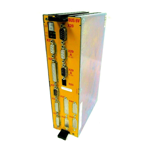
Baumuller BUS 6-T Series Parts list manual

BAUMÜLLER
Technicaldescriptionand
operationmanual
EditionNovember1995
CONTROLLER
BUS6T
E5.94017.06

BAUMÜLLER
CONTROLLER
BUS 6 T
Technical description and operation manual
Edition November 1995
5.94017.06
PLEASE READ AND PAY ATTENTION TO SAFETY INSTRUCTIONS
AND OPERATING GUIDE PRIOR TO COMMISSIONING
This manual contains the necessary information for normal opteration of the products described
therein. The drives may only be used, maintained and repaired by personnel familiar with the operation
manual and the applicable regulations on working safety and accident prevention. The devices are
manufactured to a high technical specification and are operationally safe. Provided that all safety
instructions habe been adhered to, there will be no personal danger during the installation and
commissioning stages.
The commisioning is prohibited until it has been positively determined that the machine, into which
these components are to be incorporated, complies with EC machine regulations.
This technical description replaces and nullifies all provious description. In order to provide the best
possible service, we reserve the right to alter information without notice.
Manufacturer and Baumüller Nürnberg GmbH
Supplier's address: Ostendstr. 80
90482 Nürnberg
Germany
Tel. (++49-911) 5432 - 0 Fax (++49-911) 5432 - 130
Copyright: The technical description and the operation manual may not be copied or
duplicated without our permission.
Country of origin: Made in Germany
Date of manufacture: Determined from the serial number on the machine/motor.

Table of contents
Controller BUS 6 T I
Baumüller Nürnberg GmbH 5.94017.06
TABLE OF CONTENTS
1 Safety notes....................................................................................................... 1
2 Technical data ................................................................................................... 5
2.1 General.......................................................................................................................5
2.2 Electrical data.............................................................................................................7
2.3 Type code...................................................................................................................10
3 Transport, removal of the packaging .............................................................. 11
4 Assembly ........................................................................................................... 13
4.1 Dimensions.................................................................................................................14
4.2 Assembly notes...........................................................................................................15
5 Installation ......................................................................................................... 17
5.1 Hazard notes ..............................................................................................................17
5.2 Checks prior to installation..........................................................................................18
5.3 Display........................................................................................................................19
5.4 Terminal diagram I......................................................................................................20
5.5 Terminal diagram II (only SV 03.05H and SV 03.07H) ................................................21
5.6 Connector location diagram........................................................................................22
5.7 Connector pin assignment...........................................................................................23
5.8 Connection cable........................................................................................................31
5.8.1 Connection cable for resolver or incremental encoder..................................31
5.8.2 Serial connection cable for PC.....................................................................32
5.9 Accessories ................................................................................................................33
6 Commissioning ................................................................................................. 35
6.1 Identification power unit..............................................................................................37
6.2 Initial commissioning of the drive system....................................................................38
6.3 Optimisation in the main spindle area.........................................................................42
6.4 Optimisation in C axis mode.......................................................................................44
6.5 Torque control.............................................................................................................45
6.6 Position control...........................................................................................................47
6.7 Spindle positioning......................................................................................................48

Table of contents
II Controller BUS 6 T
5.94017.06 Baumüller Nürnberg GmbH
7 Parameters......................................................................................................... 49
7.1 Function diagram........................................................................................................49
7.2 Basic settings..............................................................................................................50
7.2.1 Basic settings (menu page 1 - 2)..................................................................51
7.2.2 Motor-specific values (menu pages 3 - 5) ....................................................57
7.3 Display and measuring parameters.............................................................................63
7.3.1 Display of nominal and peak values (menu page 6).....................................63
7.3.2 Random-check generator - square-wave generator (menu page 7)............64
7.3.3 Characteristic curve of magnetisation (asynchronous machines only)..........66
7.3.4 Temperature monitoring ..............................................................................67
7.3.5 Measuring channel 1 and 2..........................................................................69
7.3.6 Display of controller parameters ..................................................................71
7.4 Parameter set 0..........................................................................................................73
7.4.1 Velocity and ramp function generator...........................................................74
7.4.2 Rounding generator and torque....................................................................77
7.4.3 Speed controller..........................................................................................79
7.4.4 Messages - monitoring.................................................................................82
7.5 Parameter set 1..........................................................................................................84
7.6 Parameter set 2..........................................................................................................86
7.7 Parameter set 3..........................................................................................................88
7.8 Encoder evaluation.....................................................................................................90
7.9 Set adaptation ............................................................................................................93
7.10 Position control (asynchronous motors)....................................................................94
7.10.1 Position control and reference run .............................................................94
7.10.2 Spindle positioning.....................................................................................97
8 Maintenance....................................................................................................... 99
8.1 Maintenance notes......................................................................................................99
8.2 Status messages ........................................................................................................100
8.2.1 Error messages ...........................................................................................101
8.2.2 Warnings and messages..............................................................................107
8.3 Disposal......................................................................................................................110
9 Appendix............................................................................................................ 111
9.1 Manufacturer´s declaration .........................................................................................111
9.2 Index ..........................................................................................................................112

Abbreviations
Controller BUS 6 T III
Baumüller Nürnberg GmbH 5.94017.06
ABBREVIATIONS
ϑM1 Temperature 1
ϑM2 Temperature 2
τRRotor time constant
AC Alternating current
AM Asynchronous motor control
BSA Reference potential analog
BSD Reference potential digital
DA Asynchronous motor
DC Direct current
DS Synchronous motor
fϑM1 Slip frequency at motor temperature 1
f2N Slip frequency
MSP Main spindle
IαGMagnetising current limitation
IβGActive current limitation
IαNSet magnetising current
IβNSet active current
ID no. Identification number
INSet apparent current
ING Apparent current limitation
PI Pulse inhibit
LP Board
M Torque
Mdx Torque limit
MNNominal torque
n Speed
nNNominal speed
NTC Negative temperature coeffizient
nxSpeed threshold
P Power
Pkzx Power threshold
PNNominal power
PTC Positive temperature coeffizient
PWM Pulse width modulation
CI Controller inhibit
SM Synchronous controlling
tBBraking time in case of controller inhibit
te3 * τR
tiWindow time
TM Temperature motor
X Plug

Abbreviations
IV Controller BUS 6 T
5.94017.06 Baumüller Nürnberg GmbH

Safety notes
Controller BUS 6 T 1
Baumüller Nürnberg GmbH 5.94017.06
1 SAFETY NOTES
Foreword
Relatively high leakage to ground occurs in the converter and the motor, i.e. the drive may be
incompatible with residual current protective devices.
In operation, the unit is protected against direct handling in such a way that it is suitable for
installation in enclosed electrical operating areas (pr EN 50178: 1994, sect. 5.2.11.2 und appendix A
5.2.11.2 terminal 7).
A high-voltage test according to pr EN 50178:1994 is to be carried out during routine tests on this unit.
General notes
This manual contains the necessary information for normal operation of the products described
therein. It is intended for technically-qualified personnel who are setially trained and are familiar in
detail with all warnings and maintenance tasks.
The units/systems are finished to the highest standard and are safe and reliable. They can be
installed and operated safely, and function without problem if the following cautionary notes are
heeded.
WARNING
Due to the nature of electrical equipment, certain parts of this unit carry dangerous voltage during
operation.
Serious injury and/or damage to property can result from non-compliance with these safety notes and
warnings.
Only qualified personnel familiar with the safety instructions, and instructions regarding assembly,
maintenance and operation are to work on this unit.

Safety notes
2Controller BUS 6 T
5.94017.06 Baumüller Nürnberg GmbH
Hazard notes
The following notes are for your personal safety on the one hand, and on the other, the protection of
the described product or connected equipment from damage.
The terms used have the following definitions both within the scope of this manual and in the notes on
the product itself:
DANGER
DANGER means that death, serious injury or considerable material damage will occur if the safety
precautions are not met.
WARNING
WARNING means that death, serious injury or considerable material damage can occur if the safety
precautions are not met.
NOTE
NOTE points to important information on the product, the manipulation of the product, or a particular
part of the documentation.

Safety notes
Controller BUS 6 T 3
Baumüller Nürnberg GmbH 5.94017.06
Qualified personnel
Qualified personnel, in the sense of the safety notes in this handbook or on the products themselves,
are persons who are familiar with the installation, assembly, commissioning and operation of the
product and are correspondingly qualified, i.e.
-are trained or authorised to commission, ground and designate electrical circuits and appliances
according to the required safety standards.
-are trained or authorised in the care and operation of applicable safety equipment according to the
required safety standards.
Normal use
WARNING
The unit/system may only be used as set in the system manual, and only with other units and
components recommended or approved by BAUMÜLLER NÜRNBERG GmbH.
Unauthorised conversion of the unit/system is not permitted for safety reasons.
The user is obliged to report any changes which may affect the safety of the unit/system immediately.
For the best use of the equipment, operating instructions should be adhered to and regular service
und insettions should be undertaken.

Technical data
4Controller BUS 6 T
5.94017.06 Baumüller Nürnberg GmbH

General Technical data
Controller BUS 6 T 5
Baumüller Nürnberg GmbH 5.94017.06
2 TECHNICAL DATA
2.1 General
This motor controller from the BMS series, referred to as Technology Controller, is particularly
designed for high flexibility and highly demanding control tasks. A powerful 32-bit microprocessor is
used for the computing tasks.
Control system:
•Field-oriented control for asynchronous motors with encoder system ROD 486 or
synchronous motors with resolver
•Control types
asynchronous motor
speed control
torque control
reference run
position control
M19 spindle positioning
synchronous motor
speed control
torque control
•Digital control with 32-bit microprocessor using SMD technology components
•4 parameter sets are deposited in the non-volatile memory and can be switched in
online mode
•Digital control offers
drift-free operation
excellent concentricity properties
high control dynamic response and rigidity in the whole speed range
control range of asynchronous motor with encoder system ROD 486
digital set value setting (PC
1 : 1 000 000 referring to nominal
analog set value setting:
MSP operation 1 : 250 referring to 8000
C axis 1 : 1000 (up to 100 rpm) referring to 8000 rpm
control range of synchronous motor with resolver
digital set value setting (PC):
1 : 10 000 referring to nominal
analog set value setting:
MSP operation 1 : 250 referring to 8000 rpm
C axis 1 : 1000 (up to 100 rpm) referring to 8000 rpm

Technical data General
6Controller BUS 6 T
5.94017.06 Baumüller Nürnberg GmbH
•Depending on requirements, the controller can be operated
analog set value settings and switching inputs
serial interface RS 232 for PC operation, parameter assignment, commissioning and
service as well as for archiving the controller parameters on floppy disk
Inputs:
2 digital inputs for parameter set switching
1 digital input (programmable function by Baumüller)
1 digital input to delete error buffer
RS 232 with a transmission rate of 9.6 kbaud
Outputs:
programmable functions (2 digital outputs programmable by Baumüller)
analog outputs (resolution 8 bit)
2 measuring channels (resolution 12 bit)
2 programmable functions by Baumüller
Encoder modules:
sine incremental encoder ROD
resolver
incremental encoder emulation
I/O option board for analog interface:
analog inputs
- set speed value input for main spindle
- set speed value input for C axis
- torque limiter
- additional set speed value input (for both MSP and for C axis)
analog outputs
- actual speed value
- actual torque value
digital inputs
- switching between MSP/C axis operation
- drive halt
- controller enabling
- pulse enabling
digital outputs
- error messages
- warnings
- programmable function by Baumüller
relay outputs
- torque limit reached
- set speed value reached
- speed = 0
- ready for use

Electrical data Technical data
Controller BUS 6 T 7
Baumüller Nürnberg GmbH 5.94017.06
2.2 Electrical data
The electrical data varies according to the relevant basic unit and is described in the applicable
documentation.
Technical data of the controller:
Accuracy of whole system Calculation accuracy 16 bit
Resolver recording resolution 12 / 14 / 16 bit switchable
ROD 486 resolution 20 bit
Speed controller cycle rate 1 ms
Torque controller cycle rate 1 ms
4 analog inputs
voltage range
type
input resistance
resolution fo speed
set value input
-10 V ... +10 V
differential input
ca. 40 kΩ
12 bit
8 potential free inputs
low level
high level
input resistance
0 V ... +5 V
+11 V ... +35 V
> 5 kΩ
4 analog outputs (optional)
voltage range
maximum output current
resolution
-10 V ... +10 V
1 mA
12 Bit
4 relay outputs
maximum contact load
maximum potential against electronic
ground
24 V DC / 1 A
50 V
6 potential free outputs
joint supply voltage
joint ground
output current
+ 24 V / 60 mA
Masse der 24 V extern
20 mA
Interfaces RS 232
Current consumption controller +24 V/1.1 A

Technical data Electrical data
8Controller BUS 6 T
5.94017.06 Baumüller Nürnberg GmbH
• Cycle times if set value source is analog (ID no. 32818 = 0)
ID no. 32818 = 0 (set value source is analog)
ID no. 32819
(controlling) ID no. 32837
(set value additive) Digital input X3:13
(MSP/C axis) Cycle rates
0
(n control) 0 Low
(MSP range) - MSP speed set value 4 ms
- Speed limitation 4 ms
- Digital inputs 8 ms
- Digital outputs 8 ms
- Display speed actual value 16 ms
- Display torque actual value 16 ms
1 Low
(MSP range) - MSP speed set value 4 ms
- Additional speed set value 8 ms
- Speed limitation 4 ms
- Digital inputs 8 ms
- Digital outputs 8 ms
- Display speed actual value 16 ms
- Display torque actual value 16 ms
0 High
(C axis range) - C axis speed set value 4 ms
- Limitation torque 4 ms
- Digital inputs 8 ms
- Digital outputs 8 ms
- Display speed actual value 16 ms
- Display torque actual value 16 ms
1 High
(C axis range) - C axis speed set value 4 ms
- Additional speed set value 8 ms
- Limitation torque 8 ms
- Digital inputs 8 ms
- Digital outputs 8 ms
- Display speed actual value 16 ms
- Display torque actual value 16 ms
1
(M control) 0 without influence - Torque set value 4 ms
- Limitation torque 4 ms
- Digital inputs 8 ms
- Digital outputs 8 ms
- Display speed actual value 16 ms
- Display torque actual value 16 ms

Electrical data Technical data
Controller BUS 6 T 9
Baumüller Nürnberg GmbH 5.94017.06
ID no. 32818 = 0 (set value source analog)
Software version: SV_03.05H (synchronous control)
SV_03.07H (synchronous control)
see terminal diagram II
ID no. 32819
(controlling) Cycle times
0
(n control) - MSP speed set value 1 ms
- Digital inputs 8 ms
- Digital outputs 8 ms
- Display speed actual value 16 ms
- Display torque actual value 16 ms
1
(M control) - Torque set value 1 ms
- Digital inputs 8 ms
- Digital outputs 8 ms
- Display speed actual value 16 ms
- Display torque actual value 16 ms

Type code Technical data
10 Controller BUS 6 T
5.94017.06 Baumüller Nürnberg GmbH
2.3 Type code

Transport, removal of the packaging
Controller BUS 6 T 11
Baumüller Nürnberg GmbH 5.94017.06
3 TRANSPORT, REMOVAL OF THE PACKAGING
The devices are packed in the manufacturer´s works in accordance with ordering instructions.
Severe vibrations during transport are to be avoided.
Onse packaging is removed and the devices are checked for their completeness, assembly can
follow.
Packaging material consists of cardboard, corrugated caroboard and/or wood. It can be disposed of in
accordance with local disposal regulations.
Any transport damage should be reported.
DANGER
In the event of damage being sustained in transit, the device should no be connected to a supply
without prior (high voltage) testing trained personnel.
Death, serious injury or considerable damage to equipment may result should this warning fail to be
heeded.

Assembly
12 Controller BUS 6 T
5.94017.06 Baumüller Nürnberg GmbH

Assembly
Controller BUS 6 T 13
Baumüller Nürnberg GmbH 5.94017.06
4 ASSEMBLY
WARNING
The user is responsible for the assembly of the converter power unit, the motor, the transformer and
the other components according to applicable safety standards (e.g. DIN, VDE) and all other relevant
national or local regulations regarding conductor dimensions and fusing, grounding, circuit breakers,
overcurrent protection etc.
It must be ascertained that unrestricted cooling air access and outlet is available.
In operation, the apparatus is protected against direct handling in such a way that it is suitable for
installation in enclosed electrical operating areas (DIN VDE 0558 part 1, sect. 5.4.3.2.4).

Assembly Dimensions
14 Controller BUS 6 T
5.94017.06 Baumüller Nürnberg GmbH
4.1 Dimensions
Plug-in depth of cassette
•BUS 6 and BUM 62: 128.5 mm
•BUM 63/64: 131.0 mm
The total depth can only be determined in conjunction with the basic unit. In addition, it is necessary
to take into account the dimensions of the connector to be used (approx. 40 mm).
This manual suits for next models
15
Table of contents
Other Baumuller Controllers manuals
Popular Controllers manuals by other brands

LOVATO ELECTRIC
LOVATO ELECTRIC DCRL Series instruction manual

Bibby Sterilin
Bibby Sterilin Stuart SCT1 Instructions for use

Mitsubishi Electric
Mitsubishi Electric MELSEC-QS Series Safety Application Guide

Mircom
Mircom TX3-BBCX-4W Assembly

Lauda
Lauda INTEGRAL XT operating instructions

Alpine
Alpine CRM-1652RF owner's manual